 Taoli Xiao1
 Ke Xu
Ke Xu
94% of researchers rate our articles as excellent or good
Learn more about the work of our research integrity team to safeguard the quality of each article we publish.
Find out more
ORIGINAL RESEARCH article
Front. Mater. , 11 January 2024
Sec. Structural Materials
Volume 10 - 2023 | https://doi.org/10.3389/fmats.2023.1352243
This article is part of the Research Topic Recent Advances in Durability Improvement and Low-Carbon Strategy of Engineering Materials and Structures View all 17 articles
Introduction: Geotechnical engineering disasters often result from instability failures in layered and heterogeneous fissured rock masses. However, the key mechanisms governing mechanical properties and crack propagation in these rock masses remain unclear.
Methods: This study presents triaxial compression tests on double-layer rock-like specimens composed of limestone and sandstone materials, containing a single fissure, to investigate the effects of fissure angles and positions on the strength and failure modes of these double-layer specimens under varying confining pressure.
Results and Discussion: The experimental results reveal that the intact composite rock approaches the strength of sandstone but is deformation-limited by limestone. Under constant confining pressure (σ3 = 5 MPa), the fissure angle affects initial crack initiation, and fissure position dictates the failure mode and extent, while increased confining pressure induces overall shear failure in the composite rock, with the failure mode being predominantly influenced by confining pressure. Concerning mechanical deformation, augmenting the fissure angle and confining pressure substantially enhances the elasticity and ductility of the composite rock. Regarding volumetric deformation, the extent of volume shrinkage in the composite rock is influenced by both fissure angle and confining pressure, while volume expansion is influenced by fissure position. Under uniaxial compression, fissured composite rock exhibits the most unstable crack propagation, resulting in early failure. Triaxial compression shows that a higher fissure angle stabilizes crack propagation while confining pressure variation affects stability only when the fissure is in limestone. When the fissure is in sandstone, crack propagation stability remains at its highest. Furthermore, an increase in fissure angle, higher confining pressure, and changes in fissure position from sandstone through the contact interface to limestone contribute to an increasing trend in the peak strength and elastic modulus of the composite rock. Fissure-induced rock degradation is primarily influenced by the fissure angle. These findings are significant for guiding engineering construction and design, providing valuable insights to geotechnical engineers, and enhancing safety in rock engineering projects.
Following the diagenetic theory, geological formations often exhibit prominent stratification. Layered composite rock masses exhibit an alternation of soft and hard layers in the perpendicular direction to the bedding planes, resulting in distinct lithological differences compared to homogeneous rock mass (Brady and Brown, 2006). In underground geotechnical engineering, composite rocks experience varying stress conditions due to excavation and rock fragmentation. These changing in-situ stress conditions contribute to the complex deformation and failure characteristics exhibited by composite rocks (Vogel and Rast, 2000; Fairhurst, 2017; Ranjith et al., 2017). Furthermore, a rock mass is a natural geological material comprised of intact rock and discontinuities (Wittke, 2014). The discontinuities primarily include bedding planes, joints, faults, and fissures (Ivars et al., 2011). These pre-existing defects exert significant influence as release surfaces and nucleation sites for failure in the rock mass. Among the 162 roof collapse accidents in coal mines supported by anchor rods across 18 large mining areas, 107 cases were attributed to joint rock composite deterioration type roof fall. This accounts for 66.04% of the investigated accidents and is identified as the primary cause of roof collapse incidents (Jia, 2007). It is crucial to understand the coupled effects of different confining pressures and fissure characteristics on the mechanical properties and failure mechanisms of composite rocks. This benefits long-term stability analysis and disaster prevention in underground engineering projects.
In the existing research on the mechanical properties and failure mechanisms of layered composite rocks, the initial focus has been on their combination form (Guo et al., 2018; Wang et al., 2020; Yu et al., 2021a; Yu et al., 2021b; Yu et al., 2022) and contact interface parameters (Zhao et al., 2013; Zhao et al., 2015; Yin et al., 2018). In some previous studies, layered composite rocks were commonly formed by bonding rocks with different strengths together using adhesive materials (such as shale-coal, sandstone-coal, etc.). Through uniaxial compression tests, it was found that the stronger/stiffer rocks in the composite rocks restricted the lateral deformation of the weaker/softer rocks along the contact interface, ensuring consistent lateral deformation. This phenomenon is commonly known as the “interface effect” (Chen et al., 2019). Furthermore, the bond strength of the contact interface is a crucial factor that influences the failure mode of composite rocks. Strengthening the bonding strength results in an enhancement of the overall integrity and failure strength of the composite rock (Xiao et al., 1988). However, artificially simulated bond strength cannot precisely replicate the authentic stress state at the interfaces of layered composite rocks. To minimize errors arising from human factors and the limitations of unnatural conditions on rock morphology, numerous scholars have extensively conducted experiments using rock-like materials, these studies have provided more convincing conclusions (Tien et al., 2006; Yang et al., 2019; Li et al., 2021; Wang et al., 2022; Yang et al., 2023; Zhang et al., 2023; Zou et al., 2023). For instance, by formulating specific rock-like materials consisting of two different hardness materials, the effects of rock layer inclination and interlayer thickness on the deformation characteristics of composite rocks have been revealed through uniaxial compression tests. The research findings indicated that increasing the strength difference between the materials enhanced the tendency for overall relative sliding of the composite rock. On the other hand, an increase in the inclination angle weakened the deformation of the composite rock, and its compressive strength demonstrated a “U”-shaped variation with the increase in the inclination angle (Yang et al., 2019); thicker interlayers in composite rocks are more susceptible to failure compared to thinner interlayers (Li et al., 2021). Moreover, the deformation of composite rocks under stress is a crucial indicator for evaluating underground construction safety. Through various types of tests, including different loading rates (Huang and Liu, 2013; Ma et al., 2021), cyclic loading and unloading tests (Song et al., 2012; Zuo et al., 2013), static-dynamic loading tests (Liu, 2014; Liu et al., 2014), as well as triaxial compression tests (Lu et al., 2019; Lu et al., 2020; Yu et al., 2021a; Yu et al., 2021b; Yu et al., 2022), researchers further revealed the influence of different stress loading paths on composite rocks, basically in terms of the compressive strength, the deformation modulus, the crack propagation, and the failure behavior. Considering the distinct dynamic properties of rocks compared to their static responses (Du et al., 2020a; Jiang et al., 2021), dynamic impact loading tests have also been conducted on composite rocks with the split Hopkinson pressure bar (SHPB) system. It was found that composite rocks exhibit a higher degree of energy accumulation compared to single rocks, requiring less energy in the event of dynamic disasters (Liu et al., 2021). These testing results provide a comprehensive evaluation of the strength, deformation characteristics, and energy dissipation of composite rocks under different stress conditions.
Compared with existing research on composite rocks, the investigation of crack propagation mechanisms in loaded fissured rocks has primarily concentrated on homogeneous rocks. The study of fissures in rocks follows a qualitative-to-quantitative progression. When considering single fissures without taking into account the mutual interactions of multiple fissures, researchers have mainly focused on the geometric characteristics of fissures, including their length (Bi and Zhou, 2017; Chen et al., 2018; Laghaei et al., 2018; Wang et al., 2018; Ismael and Konietzky, 2019), angle (Cheng et al., 2018; Le et al., 2018; Miao et al., 2018; Wang et al., 2018), width (Wang et al., 2018), and the materials filling (Le et al., 2018; Miao et al., 2018). These studies aim to investigate the impact of these fundamental fissure forms on the mechanical and deformation characteristics of rocks. When considering the interactions of multiple fissures, researchers have shifted their focus to rock bridges (length and angle of rock bridges) (Feng et al., 2019; Du et al., 2020b; Yan et al., 2023), the arrangement patterns of fissure clusters (angle, length, and spacing of fissure clusters) (Lee and Jeon, 2011; Cao et al., 2016), and the combination of fissures with voids (Lin et al., 2020; Zhang et al., 2021). Specifically, the research has yielded the following findings: It is generally believed that the length of fissures inevitably degrades the mechanical properties of rocks. However, when considering the combined effects of fissure angle and length, the conclusion is not absolute. It is argued that the peak strength of fissured rocks demonstrates a quadratic relationship with the fissure angle, while the elastic modulus shows a linear increase with the fissure angle (Feng et al., 2019). Besides, the propagation of cracks in rock masses is influenced by both the number of fissures and the fissure angle (Lin et al., 2020; Zhang et al., 2021). Wong et al. (2004a); Wong et al. (2004b); Wong et al. (2006) also gained significant insights, such as the fact that the mode of surface crack propagation in rock masses is influenced by the ratio of crack depth (d) to rock thickness (t), represented by d/t: when d/t > 1/3, the crack propagation length is larger, resembling the extension of two-dimensional cracks; when d/t < 1/3, the dominant failure mode in the rock involves anti-wing cracks. It is worth noting that all the literature mentioned above is concentrated on homogeneous rocks, the investigation of composite rocks containing fissures is rather limited. Recently, (Hu et al., 2020; Ma et al., 2023), conducted uniaxial loading tests on fissured layered composite rocks to investigate the impact of fissures on the development and evolution of cracks, as well as the final failure mode of the composite rock.
From the foregoing, considerable efforts have been devoted to studying the anisotropic behavior of transversely isotropic rocks and the impact of fractures on the mechanical properties and failure modes of homogeneous rocks. However, the stress environment of the rock mass, such as the confining pressure, should be considered as a significant influencing factor. Therefore, a comprehensive understanding of the different stress environments, mechanical deformation characteristics, and crack propagation paths of fractured layered composite rocks are crucial for improving the efficiency of deep underground resource exploitation, effectively preventing and controlling hazards in engineering construction, and providing a theoretical basis for practical engineering. However, the study of the fissured composite rock under confining pressure conditions has never been investigated. This study has produced composite rock specimens containing a single fissure and conducted triaxial compression tests. Specifically, the influence of fissure angles and positions on stress-strain response, damage stress, peak strength, elastic moduli, and failure modes under different confining pressures of composite rocks was analyzed and summarized.
In the natural environment, rocks are composed of diverse mineral particles and cementing materials that are bonded together. And their mechanical properties are mainly affected by the friction between particles. Considering that sand particles can provide a frictional force, cement mortar was chosen as the rock-like material for this experiment.
Sedimentary rocks, which account for approximately two-thirds of the Earth’s land area, are widely distributed on the Earth’s surface. To create composite rock-like materials, limestone and sandstone were chosen as the original rocks, which exhibit distinct differences in physical properties and are commonly found in sedimentary rocks. The quartz sand was used as an aggregate of rock-like material. To ensure a smooth specimen surface, the size gradation distribution of the selected quartz sand particles is presented in Table 1. P.O42.5 Portland cement, silica fume, and iron powder were used as limestone-like materials. The purpose of using silica fume was to lower the peak temperature of the material’s curing reaction and prevent cracking. The purpose of selecting iron powder was to improve the density of the rock. To differentiate the sandstone in terms of mechanical properties and visual appearance, P.W.32.5 Portland cement was used in its production. Additionally, a small amount of water reducer and defoamer was added to enhance the fluidity of the material and minimize the formation of pores. Table 2 provides the mass ratios of rock-like material. Table 3 presents the physico-mechanical parameters of cement mortar, which are close to that of natural rocks (Nazir et al., 2013; Cai et al., 2022). Therefore, cement mortar is considered an ideal rock-like material for laboratory experiments.
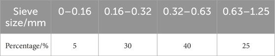
TABLE 1. The particle grading distribution of quartz sand.
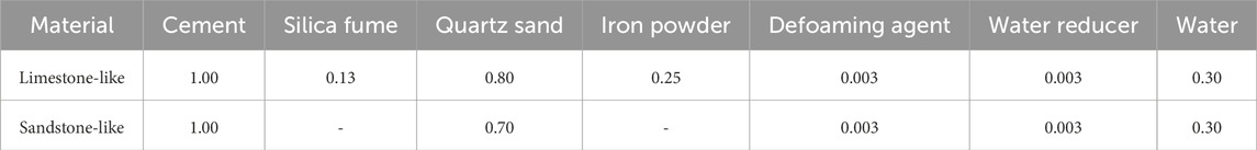
TABLE 2. Material mass ratios of rock-like.
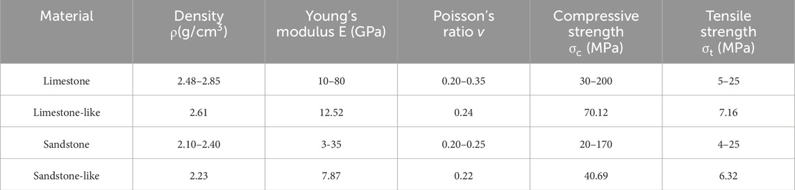
TABLE 3. Physico-mechanical parameters of rock and rock-like.
During the solidification process, cement tends to form a thin layer on the surface (Wang et al., 2018), which is prone to cracking under compression. To ensure accurate observation of real cracks in the specimens, this study first, poured cubic specimens (height × width × thickness = 150 × 150 × 150 mm) and then obtained cylindrical specimens by drilling, as illustrated in Figure 1A For cubic specimen casting, custom molds were created using plastic, steel sheets (15 mm length, 0.5 mm thickness), and spacer boards. Vibrations were applied to the mold during pouring to eliminate trapped air from the slurry. After 30 min, the spacer board was removed to ensure sufficient strength at the contact surface between the two types of rock materials. After 8 h, the steel sheets were removed when the specimens reached the initial setting, resulting in through-opened fissures. After 24 h, the solidified specimens were de-molded and placed in a constant temperature and humidity curing chamber (temperature set to 20°C ± 2°C and humidity set to 85% ± 5%) for 28 days before conducting cylinder specimen drilling.
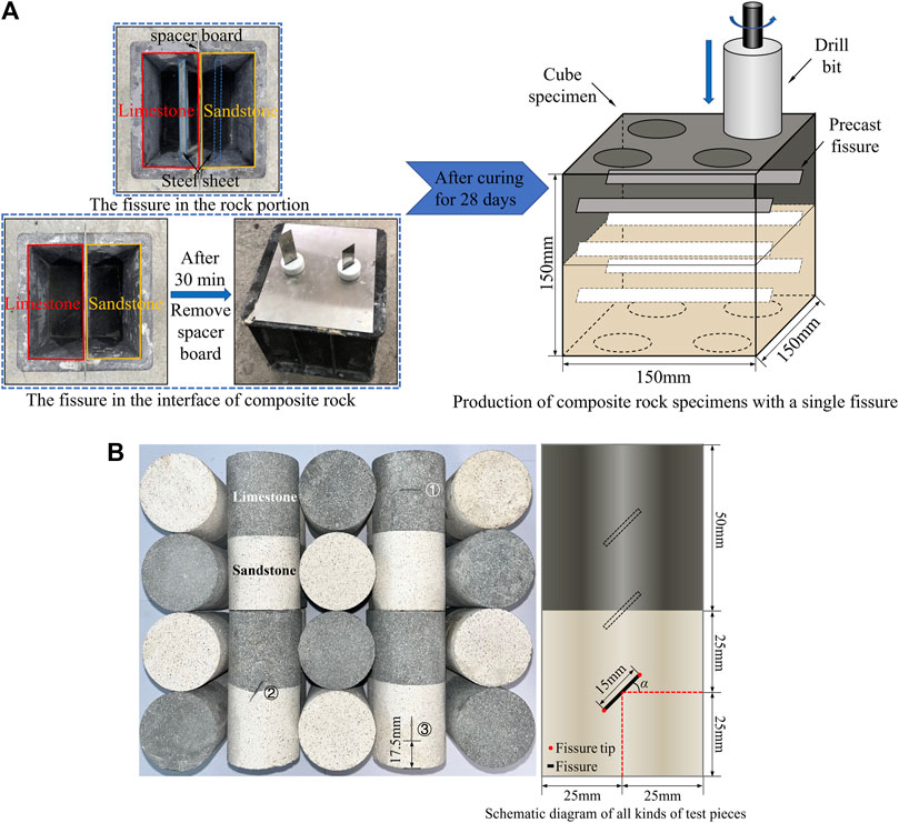
FIGURE 1. Specimens making and processing. (A) Schematic drawing of cube specimens making and processing, (B) Schematics of fissure geometry configuration in the specimens.
Following the guidelines of the International Society for Rock Mechanics (ISRM), cylindrical specimens were cut and ground to a height of 100 mm and a diameter of 50 mm. To facilitate the analysis of the effects of fissure angle, position, and confining pressure on the specimens and to prevent the mechanical failure patterns of the specimens from being universally applicable due to excessively long fissure lengths, the fissure length was fixed at 15 mm. Five fissure angles (α) were considered: 0°, 30°, 45°, 60°, and 90°. Three different fissure positions were established: ①at the center of the limestone, ②at the center of the contact interface (in this study, the term “interface” is used to describe the contact interface parameters of limestone and sandstone), and ③at the center of the sandstone, as shown in Figure 1B Four different confining pressures (σ3) were applied: 0, 5, 10, and 15 MPa. Considering the uniaxial compressive strength of the simulated sandstone as 40 MPa, and ensuring that the deformation of the specimen remains in the elastic stage during the confining pressure process (typically, the ratio of the threshold stress for sandstone fracturing to the peak stress is approximately 0.5), the maximum value of confining pressure was set to 15 MPa.
For clarity, the specimen numbering is designated as fissure position (FL, FI, FS, C) - fissure angle (α) - confining pressure (σ3), where FL, FI, FS, and C represent the fissure positions in limestone, interface, sandstone, and the complete composite rock specimen, respectively. For instance, C-5 denotes the complete composite rock specimen under a confining pressure of 5 MPa. FL-45-15 signifies a composite rock specimen with a fissure angle of 45° located in limestone under a confining pressure of 15 MPa. The specific specimen numbering is outlined in Table 4. To obtain more universally applicable experimental data and avoid significant variability in individual specimens, each set of specimens underwent four tests. After removing specimens with noticeable variability, the average of the remaining specimen data was taken as the result for each set of specimens. This approach helps reduce the impact of individual outlier test data on the overall results, enhancing the reliability of the experimental outcomes.

TABLE 4. Specimens’ numbers and fissure geometry parameter values used for all specimens.
Triaxial compression strength (TCS) test was processed by HYAS-1000C electrohydraulic servo-controlled testing equipment at the geotechnical mechanics and engineering research center at Yangtze University in China, as shown in Figure 2. In the experiment, the confining pressure was applied using hydraulic oil, while the axial stress was controlled by axial displacement. Before applying the confining pressure, the specimen was placed between the upper and lower platens and encapsulated with heat-shrinkable tubing to prevent hydraulic oil from infiltrating the rock and affecting the test results. The axial and radial strains of the specimen (at the middle section) were simultaneously measured using axial and radial extensometers, with a measurement range of 0–4 mm and a reading accuracy of ±1% at room temperature. Data collection was performed directly by a computer. The test was conducted in two steps as follows: (a) The confining pressure was increased to the target value at a rate of 0.5 MPa/min, then the axial compression was applied to the specimen at a rate of 1 mm/min until reaching an initial axial stress of 2 KN. Additional axial stress (also called deviator stress) was applied to the specimen at a rate of 0.2 mm/min until it experienced unstable failure (Yu et al., 2021b).
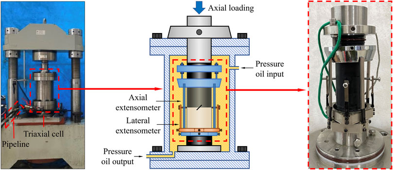
FIGURE 2. Electrohydraulic servo-controlled testing equipment.
To better investigate the mechanical properties of fissured composite rock samples, uniaxial compression tests were initially conducted on individual sandstone, individual limestone, and intact composite rock, and the stress-strain curves and equivalent mechanical parameters are obtained, as shown in Figure 3 and Table 5.

FIGURE 3. Stress-strain curves and change in mechanical of three intact rock specimens. (A) Stress-strain curves and failure modes, (B) Mechanical parameters.
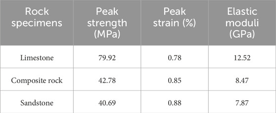
TABLE 5. Mechanical parameters and failure characteristics of the three configurations of rock specimens.
Figure 3A illustrates notable distinctions among the three specimens, particularly in the pre-peak stage. The limestone’s compaction phase is relatively inconspicuous, featuring an extended elastic phase. In contrast, composite rock and sandstone show significant compaction stages, with sandstone exhibiting a shorter elastic phase and a slight stress reduction just before the peak. This suggests high compaction in limestone and greater porosity in sandstone, making it more prone to macroscopic cracks before complete failure. Despite these differences, all uniaxial stress-strain curves share similar post-peak characteristics, marked by a rapid stress decline towards residual strength and a swift loss of bearing capacity.
Statistical analysis of experimental data (Figure 3B; Table 5) reveals limestone’s superior strength, surpassing composite rock and sandstone by 86.55% and 96.41%, respectively. Additionally, its elastic modulus exceeds that of composite rock by 47.82% and sandstone by 59.09%. Regarding deformation characteristics, limestone has the lowest peak strain, 12.82% less than sandstone, while the peak strain of composite rock falls between the two.
Figure 3A depicts the failure characteristics of three specimen types. Limestone and composite rock experience tensile failure along the axial compression direction, while sandstone undergoes a tensile-shear mixed failure. Deformation upon sandstone failure is notably larger than in limestone, marked by evident surface spalling. Due to lower sandstone strength, composite rock failure initiates in the sandstone portion, forming macroscopic cracks that propagate to the contact interface, penetrating through the limestone, where spalling primarily occurs.
In summary, there exists a significant strength difference between limestone and sandstone. Sandstone, being relatively softer in lithology compared to the harder limestone, exhibits larger deformations under compression. The strength of the composite rock is determined by the weaker sandstone portion, yet its deformation is constrained by the stronger limestone portion.
In the compression failure modes of rocks, cracks can be classified into three forms based on the angle between the generated cracks and fissures, as well as the scratches on the fractured surface (Lee and Rathnaweera, 2016; Lin et al., 2020; Yu et al., 2021b): (1) Axial splitting, which refers to tensile cracks formed under compression, generally parallel to the direction of maximum principal stress, mostly with an angle greater than 90° to the fissures. The crack fracture edges are neat, and the crack fractured surface is smooth, with only minor undulations in certain areas, as indicated by the red region in Figure 4A; (2) Shear cracks, typically composed of the main shear crack and secondary tensile cracks on the specimen surface. Secondary tensile cracks originate from the main shear crack and extend, with the main shear crack coplanar or less than 90° to the fissures. Most observed shear cracks exhibit evident shear dilation characteristics, with serrated fracture edges and a rough fractured surface. In the limestone portion, there is also a strong frictional effect resulting in white powder. Additionally, at lower confining pressures, shear cracks terminate at the end faces, while at higher confining pressures, shear cracks terminate at the specimen’s side, as illustrated by the blue region in Figure 4B; (3) Tensile-shear mixed cracks, observed only in some specimens. These cracks typically start as tensile cracks extending towards the ends and then shift to extend to the specimen’s side, forming shear cracks, as shown in Figure 4C.
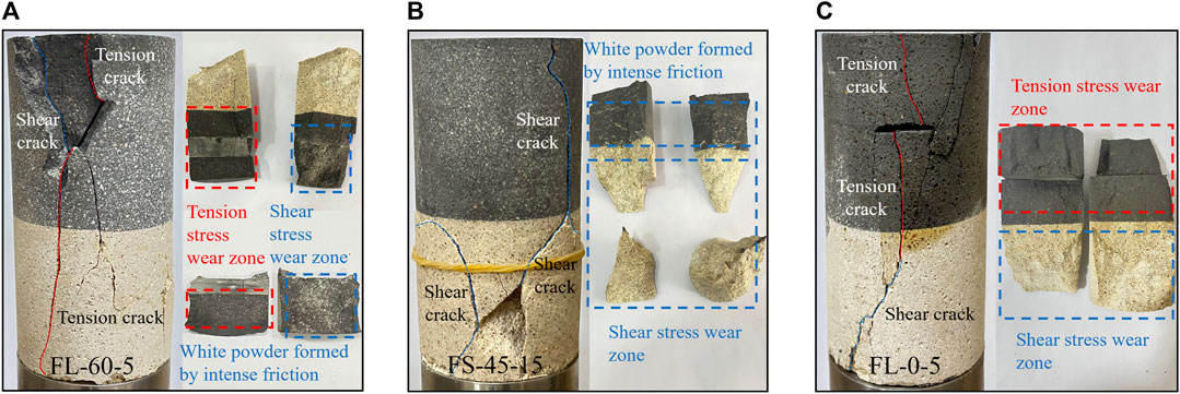
FIGURE 4. Different crack types in composite rock. (A) Typical tensile crack, shear crack, and crack fracture surface, (B) Typical shear crack and crack fracture surface, (C) Typical tensile shear mixed crack and crack fracture surface.
To visually illustrate the failure characteristics of the specimens more clearly, clear crack trajectories were plotted. The red and blue lines represent the generated main tensile cracks and main shear cracks, respectively. The black fine lines on the specimen surface depict secondary tensile cracks, which do not influence the internal structure of the specimen.
Figure 5 presents the failure modes of composite rock specimens with different fissure angles and positions under a confining pressure of 5 MPa. By comparing various aspects, the characteristics of the cracks and their aggregation forms are summarized.
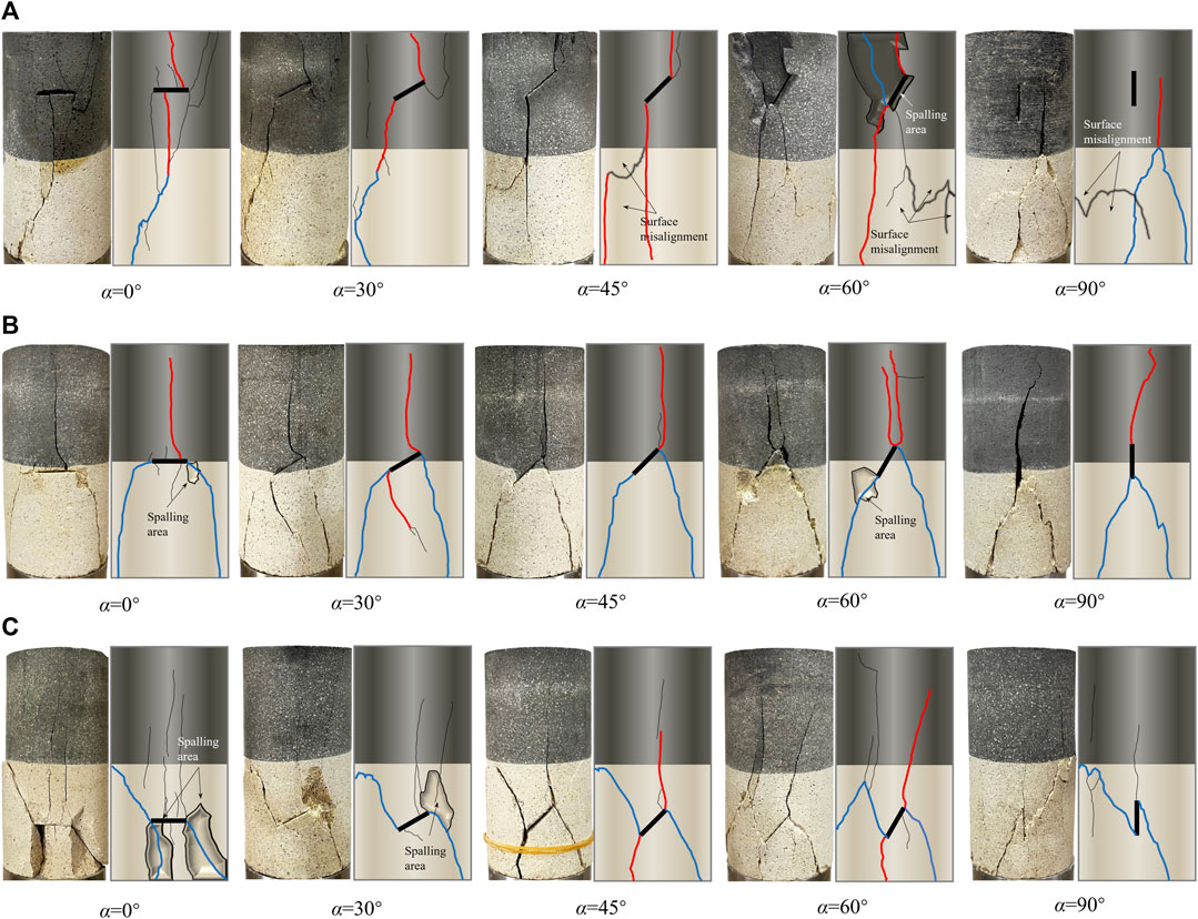
FIGURE 5. The failure mode of composite rock specimens with different fissure angles and positions (σ3 = 5 MPa). (A) Fissure is in limestone, (B) Fissure is at the contact interface, (C) Fissure is in sandstone.
Under different fissure angles: (1) When α = 0°, regardless of the rock layer in which the fissure is located, tensile cracks always initiate at the middle of the fissure and extend towards the specimen ends. This is because the fissure is perpendicular to the direction of the principal stress, and the inner surface of the fissure is in a bending state. With the increase in axial load, tensile cracks are prone to occur in the middle of the fissure. (2) When α = 30°–60°, as the region with the most concentrated stress, wing cracks or anti-wing cracks are likely to form at the tips of the fissure, resulting in similar failure modes. (3) When α = 90°, large compressive forces leading to tensile cracks are less likely to occur in the fissure. Due to the strength difference between the two types of rocks, shear cracks first initiate and propagate in the sandstone, forming a wedge shape that causes limestone to undergo splitting failure. The failure mode of the specimen mainly depends on the fissure positions.
Under different fissure positions: (1) When the fissure is in limestone, some specimens may develop a small number of shear cracks, but overall, tensile failure predominates. Under α = 0°–60°, tensile cracks generated at the lower part and the lower tip of the fissure easily propagate through the contact interface towards the sandstone end, causing overall failure of the composite rock. However, when α = 0° and 30°, due to the lower strength of the specimen, tensile cracks do not extend to the sandstone end but continue to form shear cracks in the sandstone under the action of axial compression and confining pressure. (2) When the fissure is at the contact interface position, combined with Figure 6, it is observed that in the sandstone part, shear failure leads to the formation of wedge-shaped blocks with distinct signs of sliding friction on the surface. In the limestone part, tensile failure results in a smooth and neat fracture surface, and the failure mode of the specimen is not affected by the fissure angle, exhibiting “λ-shaped failure.” This is because the strength of limestone is greater than that of sandstone, and shear cracks generated at both ends of the fissure first extend towards the sandstone end. After forming a wedge-shaped body in the sandstone portion, it continues to be compressed by axial pressure, ultimately leading to tensile failure in limestone. (3) When the fissure is in sandstone, the specimen mainly experiences localized shear failure in the sandstone. This is because the fissure further reduces the strength of the sandstone, and anti-wing shear cracks developed at the ends of the fissure receive sufficient development under lower stress levels. The cracks extend towards the sandstone end and side. Meanwhile, tensile cracks generated by the fissure extend towards the limestone but do not penetrate the limestone portion. (4) Surface sliding and spalling: Surface sliding and spalling mainly occur at the sandstone end and the tip of the fissure. This is primarily due to the sandstone portion and the tip of the fissure being more susceptible to the compressive squeezing effect of confining pressure, resulting in localized substantial shear dilation deformation.
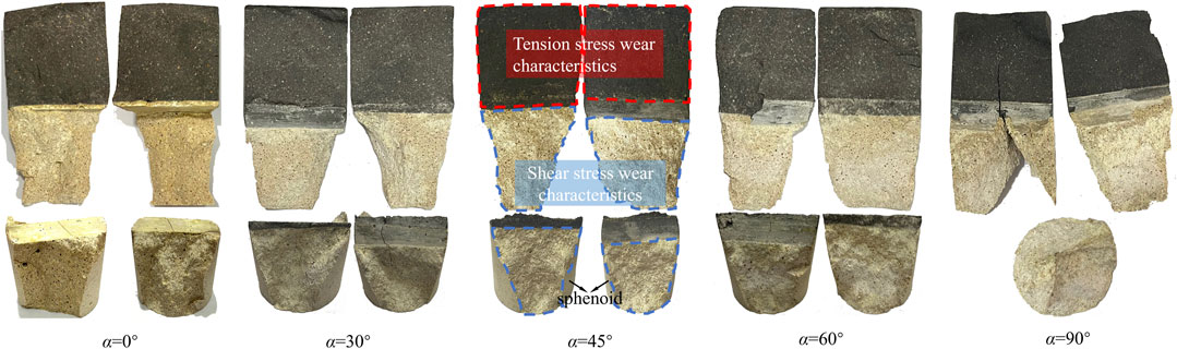
FIGURE 6. Internal wear diagram of composite rock specimens with fissure at the contact interface (σ3 = 5 MPa).
Figure 7 illustrates the failure modes of composite rock specimens under different confining pressures and fissure positions at α = 45°. Under uniaxial compression conditions, the composite rock specimens exhibit conspicuous splitting failure caused by a tensile crack extending along the direction of stress loading (cracks generated can be merged into one). With increasing confining pressure, the following observations are made: (1) The failure modes of all specimens gradually transition from tensile failure to shear failure. This is attributed to high confining pressure exerting closure forces on nearly longitudinal cracks, inhibiting the extension of wing-shaped tensile cracks. Additionally, the shear stress acting on the fissure tip becomes more significant, leading to a purer shear failure of the specimen. (2) All specimens experience overall failure. Combined with Figure 8, it is observed that due to the gradual enhancement of shear stress, shear cracks appear at the tips of the fissure in limestone, and the frictional sliding traces on the internal crack fracture surface become more apparent. This ultimately leads to the formation of wedge-shaped bodies in limestone, continuing to be compressed and resulting in overall specimen failure. When the fissure is at the contact interface and in the sandstone, co-planar shear cracks occur at both fissure tips. The specimen slides along the fissure to some extent, and the shear stress developed in the sandstone can extend shear cracks into the limestone, causing shear failure in the limestone portion as well. (3) With the increase in confining pressure, there is an increase in surface spalling. This is attributed to higher confining pressure leading to more effective compaction of the fissure. In this state, the interlocking effect at the fissure tip becomes increasingly pronounced, promoting the extensive development of secondary cracks and resulting in a greater occurrence of local spalling phenomena.
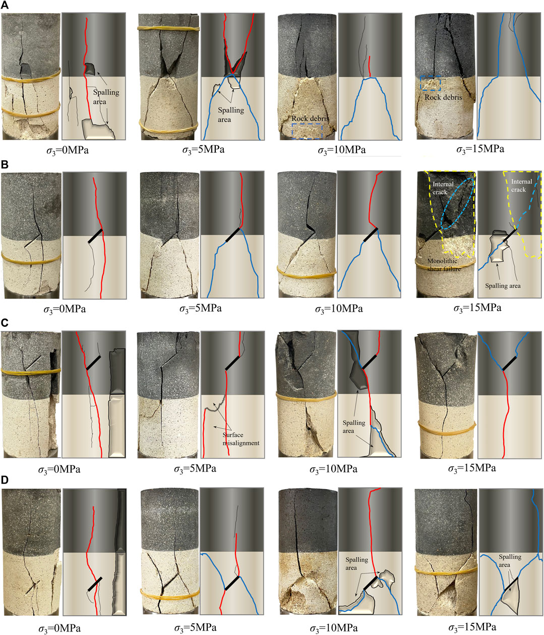
FIGURE 7. The failure mode of rock specimens under different confining pressure and fissure positions (α = 45°). (A) Intact specimen, (B) Fissure is in limestone, (C) Fissure is at the contact interface, (D) Fissure is in sandstone.
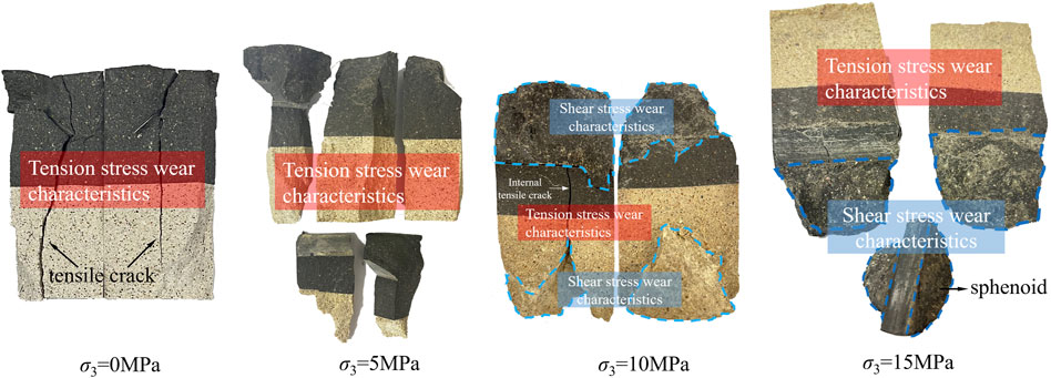
FIGURE 8. Internal wear diagram of composite rock specimens with fissure in the limestone (α = 45°).
In summary, the geometric distribution of a single fissure has a significant impact on the failure patterns of composite rocks under confining pressure conditions. The analysis of the failure characteristics of each specimen is summarized in Tables 6, 7. From Table 6, it is evident that maintaining a constant confining pressure (σ3 = 5 MPa), fissure in limestone is prone to generate tensile cracks, leading to the overall failure of the specimen. On the other hand, the fissure tips in sandstone primarily produce shear cracks that are challenging to extend through the contact interface into the limestone, resulting in local failure of the specimen. In this case, the failure mode of the composite rock is dominated by the fissure position, while changes in the fissure angle primarily influence the initiation mode of the specimens. From Table 7, under uniaxial compression conditions, the specimens primarily experience axial splitting failure. With the increase in confining pressure, the failure mode of the specimens gradually transitions from tensile failure to overall shear failure. The influence of the fissure position on the failure of the composite rock becomes less pronounced, indicating a gradual shift in the failure mode of the composite rock to be dominated by the confining pressure.

TABLE 6. The failure characteristics of composite rock specimens with different fissured angles and positions (σ3 = 5 MPa).
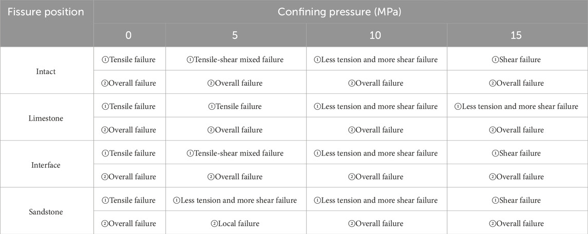
TABLE 7. The failure characteristics of composite rock specimens under different confining pressures and fissure positions (α = 45°).
Under 5 MPa confining pressure, the full stress-strain curves of specimens with different fissure angles and positions are depicted in Figure 9. The volumetric strain reflects the overall volume change of the specimen during the loading process and is calculated as follows: εV = ε1 + 2ε3. It can be observed that, with the fissure position held constant, the axial stress-strain trends of all specimens are nearly identical. In the pre-peak stage, as the fissure angle increases, the linear elastic stage of the specimen significantly extends, and the peak stress also rises, gradually approaching that of the intact specimen. However, the plastic yield stage of each specimen is more pronounced compared to the intact specimen. This indicates that an increase in the fissure angle can enhance the strength of the specimen, but the presence of fissure still increases the accumulated damage within the specimen, leading to an elongation of the plastic stage experienced by the specimen before complete failure. In the post-peak stage, due to the constraint of confining pressure, all specimens do not exhibit significant brittle failure characteristics.
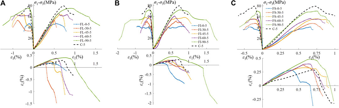
FIGURE 9. Stress-strain curve of rock specimens with different fissured angles and positions. (σ3 = 5 MPa). (A) Fissure is in limestone, (B) Fissure is at the contact interface, (C) Fissure is in sandstone.
The volumetric change trends of all specimens show a pattern of initial contraction followed by expansion. In terms of contraction, the peak volumetric strain of each specimen increases with the rise in fissure angle. This indicates that as the linear elastic stage of the specimen becomes longer with an increasing fissure angle, the ability of the specimen to contract becomes more pronounced. However, the intact rock specimen, without the presence of fissures, does not exhibit significant compression and, therefore, does not possess the strongest contraction ability. In terms of expansion, under the same fissure angle, when the fissure is in the sandstone, the specimen exhibits the weakest expansion ability. This is because the FS series specimens experience localized failure in the sandstone during destruction, resulting in a relatively insignificant overall expansion of the specimen. Therefore, at lower confining pressures (σ3 = 5 MPa), the contraction of the specimen is dominated by the fissure angle, while the expansion is dominated by the fissure position.
The full stress-strain curves of various specimens under different confining pressure levels and fissure positions are illustrated in Figure 10. Under uniaxial compression conditions, each specimen exhibits a prolonged compaction stage, sharp peaks appear at the peak stress, followed by a rapid decline after the peak. When the confining pressure is 5 and 10 MPa, the composite rock specimen with a fissure in the limestone part exhibits a stress drop during the loading process, accompanied by a sudden increase in lateral strain, indicating the initiation of macroscopic cracks. The stress-strain curves of the other two types of fissure specimens show similar behavior at this point, with the deformation characteristics of the specimen dominated by the fissure position. As the confining pressure increases to 15 MPa, the compaction stage disappears gradually. The elastic stage and yield stage before the peak becomes significantly extended, and both peak stress and peak strain increase accordingly. This is because, before axial compression, the micro-pores and micro-cracks inside the specimen have been compacted and closed by the confining pressure. After the elastic stage, the macroscopic cracks generated are constrained by the confining pressure and their crack fractured surface interlock and friction with each other. This results in a slow increase in axial bearing capacity, leading to the formation of a plastic flow state characterized by strain hardening during the yield stage. This significantly enhances the strength and ductility of the specimen. At this point, the influence of the fissure position on the mechanical deformation characteristics of the rock specimen diminishes, gradually being dominated by the confining pressure.
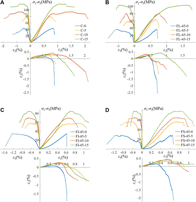
FIGURE 10. Stress-strain curve of rock specimens with different confining pressures and fissure positions (α = 45°). (A) Intact specimen, (B) Fissure is in limestone, (C) Fissure is at the contact interface, (D) Fissure is in sandstone.
Under uniaxial compression conditions, the maximum values of volumetric contraction for all specimens are relatively small and similar. With the increase in confining pressure, the maximum values of volumetric contraction for most specimens become closer, showing an overall trend of slow growth at high confining pressures. In terms of volumetric expansion, regardless of the magnitude of the confining pressure, the degree of volumetric expansion in the composite rock specimens with a fissure in the sandstone portion is the smallest. Even after complete failure under high confining pressure, the overall volume remains contracted. The reason is that when the fissure is in the sandstone, the damage to the limestone part is minimal, resulting in the smallest overall expansion of the specimen. Therefore, the volumetric contraction of the specimen is dominated by confining pressure, while volumetric expansion is dominated by the fissure position.
The crack damage threshold (σcd) is crucial in the rock failure process, representing the axial stress corresponding to the volumetric strain peak (Lee and Rathnaweera, 2016). Before reaching σcd, the volumetric strain caries in the same direction as the axial stress, therefore the specimen is characterized as in a compaction stage, indicating that the specimen is in the compression stage, and the cracks are steadily expanding. Once the axial stress exceeds σcd, the volumetric strain decreases continuously, indicating that the specimen enters the dilation stage. At this point, cracks begin to connect, intersect, and penetrate, evolving into a macroscopic fracture surface. The crack extension enters an unstable stage, and irreversible damage occurs in the specimen (Huang et al., 2016). The relative damage threshold (σcd/σc) serves as a reliable indicator for predicting specimen failure (Wu et al., 2018). A smaller value implies earlier dilation and more unstable crack propagation.
Figure 11 illustrates the variations of crack damage threshold (σcd) and relative damage threshold (σcd/σc) of rock specimens with different fissure angles and positions. As shown in Figure 11A, the damage stress (σcd) of the composite rock specimens with fissure at the contact interface and in the sandstone increases significantly with the fissure angle, by 187.11% and 112.62%, respectively. However, when the fissure angle α < 45° and the crack is in the limestone, the damage stress (σcd) of the composite rock samples shows a negative correlation with the crack angle. Combining the analysis of the failure modes of the specimens in Figure 5A, it can be explained that when α = 0°–45°, the proportion of tensile cracks in the FL series specimens gradually increases and becomes purer. The generation of tensile cracks not only significantly reduces the strength of the specimens but also increases lateral deformation, causing an overall increase in specimen volume. In Figure 11B, it can be observed that the relative damage threshold of the FS series specimens remains consistently the highest and exhibits the most gradual trend, indicating that the crack propagation is most stable when the fissure is in the sandstone. When α = 90°, the relative damage threshold of all specimens is almost the same, indicating the lowest level of damage caused by the fissure at this angle.
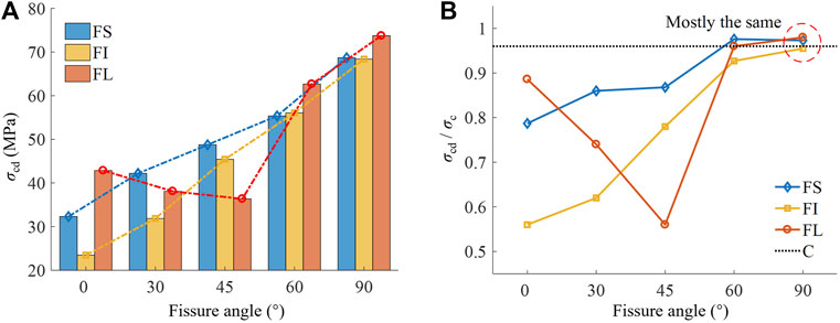
FIGURE 11. Crack damage threshold behavior of rock specimens under different fissure angles and positions (σ3 = 5 MPa). (A) Crack damage threshold, (B) Ratios of σcd to peak strength σc.
Figure 12 displays the crack damage threshold (σcd) and the relative damage threshold (σcd/σc) of rock specimens under different fissure positions and confining pressures. In Figure 12A, it is evident that σcd for each specimen increases with the rise in confining pressure. As the confining pressure increases from 5 to 15 MPa, the growth rates of σcd for the FS, FI, FL, and C series specimens are 41.35%, 12.09%, 141.28%, and 39.79%, respectively, with FL series showing the highest increment. When σ3 is 5 and 10 MPa, the FL series specimens exhibit the lowest damage stress σcd. This is attributed to the fissure in the limestone that is prone to the early formation of macroscopic tensile cracks. However, under the constraint of confining pressure, the crack surfaces fractured interlock with each other, allowing the specimen to continue gaining higher bearing capacity. This also explains why some FL specimens exhibit stress drops during the loading process. Figure 12B, under uniaxial compression, the relative damage thresholds of fissured specimens show minimal variation, remaining between 0.36 and 0.43, significantly lower than that of intact specimens. Under triaxial compression, with constant confining pressure, the relative damage thresholds of the FS, FI, and FL series specimens decrease sequentially. When the fissure position remains unchanged, the relative damage threshold of the FL series increases with the rise in confining pressure, while those of the FI and FS series specimens remain stable. It is observed that during uniaxial compression, the fissure has a severe weakening effect on the expansion strength of specimens, and the unstable expansion of cracks occurs earliest, with minimal influence from changes in fissure position. When the fissure is in the sandstone, the expansion of cracks in the composite rock specimens remains stable.
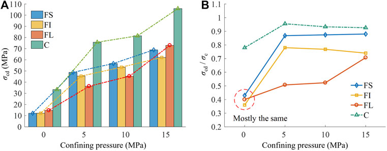
FIGURE 12. Crack damage threshold behavior of rock specimens under different confining pressures and fissure positions (α = 45°). (A) Crack damage threshold, (B) Ratios of σcd to peak strength σc.
The peak stress (σc) and relative peak stress (σc/σi) of each specimen under different fissure angles and positions are shown in Figure 13. The relative peak stress indicates the ratio of peak strength between specimens with fissures and intact specimens, reflecting the degree of deterioration in rock with fissures, a smaller numerical value corresponds to a greater degree of deterioration.
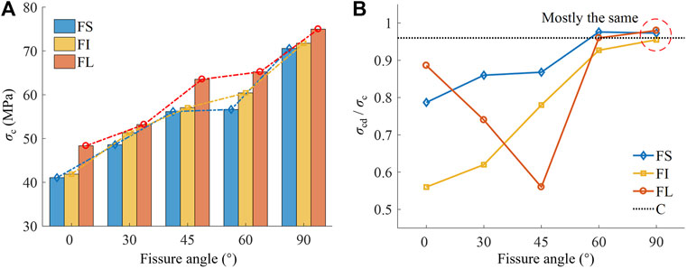
FIGURE 13. Peak stress behavior of rock specimens under different fissure angles and positions (σ3 = 5 MPa). (A) peak stress, (B) ratios of σc to σI.
As depicted in Figure 13A, the peak stress of each specimen increases with the rise in fissure angle and position, but the growth trends vary. In the same rock layer, as the fissure angle transitions from α = 0° to α = 90°, the stress increments for the FS, FI, and FL series are 71.83%, 71.36%, and 55.09%, respectively. Under the same fissure angle, the stress increments from the FS series to the FL series are 17.10%, 9.44%, 6.02%, 15.17%, and 6.23%. It is evident that, under lower confining pressure (σ3 = 5 MPa), the strength of specimens is notably influenced by changes in fissure angle. Figure 13B reveals that the degree of strength deterioration in specimens is minimal when a fissure is present in limestone; larger fissure angles correspond to less deterioration in specimen strength.
The peak stress (σc) and relative peak stress (σc/σi) of each specimen under different confining pressures and fissure positions are illustrated in Figure 14. As depicted in Figure 14A, with a constant fissure position, the strengths of FS, FI, FL, and C series specimens all significantly increase with the rise in confining pressure (σ3 = 5–15 MPa), with increments of 39.28%, 46.32%, 62.31%, and 48.88%, respectively. With constant confining pressure, specimens with a fissure in limestone exhibit the highest strength, while those in sandstone show the lowest, with the maximum difference at σ3 = 15 MPa being 31.83%. This implies that when a fissure is in limestone, specimens can attain higher bearing capacity under the restriction of confining pressure. Consequently, it is evident that the influence of fissure position on the strength of composite rock specimens gradually increases with the augmentation of confining pressure. As indicated in Figure 14B, compared to changes in confining pressure, the degradation of rock is primarily affected by fissure position, with the least deterioration observed when a fissure is in limestone.
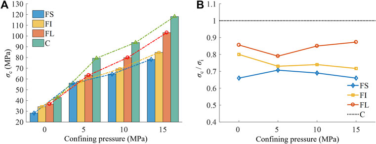
FIGURE 14. Peak stress behavior of rock specimens under different confining pressures and fissure positions (α = 45°). (A) peak stress, (B) ratios of σc to σI.
Figure 15A presents the relationship between the elastic modulus and the fissure angle for the three series of specimens. The elastic modulus increases with an increasing fissure angle, but the growth trends differ. Within the fissure angle range of 0°–90°, the FL specimens exhibit the smallest increase in elastic modulus (13.43%), while the FI specimens show the largest increase (33.31%). Keeping the fissure angle constant, except for α = 0°, the variation in elastic modulus with fissure position follows a similar pattern to the changes in peak stress. It is worth noting that the FI-0-5 specimen deviated from the expected results due to difficulties in precisely positioning the fissure in the interface, caused by mold errors.
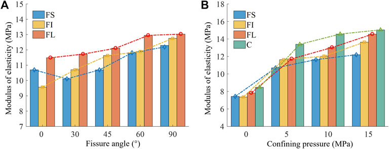
FIGURE 15. Peak stress behavior of rock specimens under different confining pressures and fissure positions (α = 45°). (A) Under different fissure angles and positions, (B) Under different confining pressures and fissure positions.
Figure 15B illustrates the variations in elastic modulus for four series specimens under different confining pressures. The experimental results indicate that, with a constant fissure position, the elastic modulus of the rock specimens significantly increases with the application of confining pressure, exhibiting an average increment of 52.43%. However, as the confining pressure increases from 5 to 15 MPa, the rate of elastic modulus growth slows down, with an average increment of 16.92%. Under fixed confining pressure, the elastic modulus of the rock specimens increases sequentially from limestone, through the contact zone, to sandstone as the crack position changes. This increasing trend becomes more pronounced with higher confining pressures.
Unlike previous studies, a series of triaxial compression tests on limestone-sandstone composite rock-like material containing a single fissure in this paper. The experimental results comprehensively evaluate the influence of the positions and inclination angles (relative to the horizontal) of a pre-existing fissure on the mechanical properties, crack evolution behavior, and failure mode under different confining pressures. The main conclusions in this study can be drawn as follows.
(1) Limestone exhibits the highest strength, while sandstone experiences the most deformation and is susceptible to early macroscopic cracking. The intact composite rock falls between sandstone and limestone in terms of mechanical deformation, with its strength controlled by the sandstone portion and overall deformation constrained by the limestone portion.
(2) At α = 0°, tension cracks develop in the middle of the fissure; at α = 90°, tension cracks are less likely. Other angles result in crack initiation at the fissure tip, with the fissure angle determining the initiation mode of initial cracks. Under low confining pressure, the fissure in limestone leads to tension cracks, causing overall failure. Conversely, the fissure in sandstone primarily produces shear cracks, causing localized failure. With increased confining pressure, the failure mode shifts from tension to shear, and the extent of damage transitions to overall failure, the factor influencing the failure mode becomes the confining pressure.
(3) Increasing the fissure angle and confining pressure prolong the linear elastic stage and enhance ductility in the composite rock. In terms of volumetric strain, Volume shrinkage is influenced by both fissure angle and confining pressure, while volume expansion is affected by fissure position. Higher fissure angle and confining pressure increase volume shrinkage, and when the fissure is in the sandstone, volume expansion is consistently minimal.
(4) Crack damage threshold serves as a crucial indicator for preventing rock mass failure. Under uniaxial compression, the crack propagation in the composite rock is the most unstable, leading to the earliest occurrence of failure. In triaxial compression with constant confining pressure, higher fissure angles lead to more stable crack propagation. With a constant fissure position, increasing confining pressure stabilizes crack propagation when the fissure is in the limestone. When the fissure is in the sandstone, crack propagation in the composite rock remains most stable. Additionally, peak strength and elastic modulus increase with higher fissure angles, greater confining pressure, and changes in fissure position from sandstone to the contact interface and limestone. As opposed to the fissure position and confining pressure, the crack degradation in composite rock is primarily influenced by the fissure angle.
The original contributions presented in the study are included in the article/Supplementary Material, further inquiries can be directed to the corresponding author.
TX: Data curation, Formal Analysis, Investigation, Software, Writing–original draft. KX: Funding acquisition, Methodology, Project administration, Resources, Supervision, Writing–review and editing. YL: Methodology, Writing–review and editing. HS: Methodology, Writing–review and editing.
The author(s) declare financial support was received for the research, authorship, and/or publication of this article. National Natural Science Foundation of China [No. 52274007], Open Fund of Hubei Key Laboratory of Oil and Gas Drilling and Production Engineering (Yangtze University) [NO: YQZC202204], Open Fund Project of Key Laboratory of Well Stability and Fluid and Rock Mechanics in Oil and Gas Reservoir of Shanxi Province [WSFRM20210101001], Open Research Fund of Key Laboratory of Reservoir and Dam Safety Ministry of Water Resources [NO: YK323003].
Author YL was employed by Jingzhou Chengfa Construction Engineering Group Co., Ltd.
The remaining authors declare that the research was conducted in the absence of any commercial or financial relationships that could be construed as a potential conflict of interest.
All claims expressed in this article are solely those of the authors and do not necessarily represent those of their affiliated organizations, or those of the publisher, the editors and the reviewers. Any product that may be evaluated in this article, or claim that may be made by its manufacturer, is not guaranteed or endorsed by the publisher.
Bi, J., and Zhou, X. (2017). A novel numerical algorithm for simulation of initiation, propagation and coalescence of flaws subject to internal fluid pressure and vertical stress in the framework of general particle dynamics. Rock Mech. Rock Eng. 50, 1833–1849. doi:10.1007/s00603-017-1204-4
Brady, B. H., and Brown, E. T. (2006). Rock mechanics: for underground mining. Berlin, Germany: Springer science and business media.
Cai, W. B., Li, Y., Gao, K., and Wang, K. (2022). Crack propagation mechanism in rock-like specimens containing intermittent flaws under shear loading. Theor. Appl. Fract. Mech. 117, 103187. doi:10.1016/j.tafmec.2021.103187
Cao, R. H., Cao, P., Fan, X., Xiong, X. G., and Lin, H. (2016). An experimental and numerical study on mechanical behavior of ubiquitous-joint brittle rock-like specimens under uniaxial compression. Rock Mech. Rock Eng. 49, 4319–4338. doi:10.1007/s00603-016-1029-6
Chen, S. J., Yin, D. W., Jiang, N., Wang, F., and Zhao, Z. H. (2019). Mechanical properties of oil shale-coal composite samples. Int. J. Rock Mech. Min. Sci. 123, 104120. doi:10.1016/j.ijrmms.2019.104120
Cheng, F. Q., Li, Z. H., Li, G. A., Wei, Y., Yin, S., Liu, S. J., et al. (2018). Influence of prefabricated fissure angle on sandstone damage and infrared radiation temperature characteristics. J. Geophys. Eng. 15, 1187–1196. doi:10.1088/1742-2140/aaacaf
Chen, X., Zhang, S. F., and Cheng, C. (2018). Numerical study on effect of joint strength mobilization on behavior of rock masses with large nonpersistent joints under uniaxial compression. Int. J. Geomechanics 18, 04018140. doi:10.1061/(ASCE)GM.1943-5622.0001260
Du, H. B., Dai, F., Xu, Y., Yan, Z. L., and Wei, M. D. (2020a). Mechanical responses and failure mechanism of hydrostatically pressurized rocks under combined compression-shear impacting. Int. J. Mech. Sci. 165, 105219. doi:10.1016/j.ijmecsci.2019.105219
Du, Y. T., Li, T. C., Li, W. T., Ren, Y. D., Wang, G., and He, P. (2020b). Experimental study of mechanical and permeability behaviors during the failure of sandstone containing two preexisting fissures under triaxial compression. Rock Mech. Rock Eng. 53, 3673–3697. doi:10.1007/s00603-020-02119-x
Fairhurst, C. (2017). Some challenges of deep mining. Engineering 3, 527–537. doi:10.1016/J.ENG.2017.04.017
Feng, P., Dai, F., Liu, Y., Xu, N. W., and Du, H. B. (2019). Coupled effects of static-dynamic strain rates on the mechanical and fracturing behaviors of rock-like specimens containing two unparallel fissures. Eng. Fract. Mech. 207, 237–253. doi:10.1016/j.engfracmech.2018.12.033
Guo, W. Y., Tan, Y. L., Yu, F. H., Zhao, T. B., Hu, S. C., Huang, D. M., et al. (2018). Mechanical behavior of rock-coal-rock specimens with different coal thicknesses. Geomechanics Eng. 15, 1017–1027. doi:10.12989/gae.2018.15.4.1017
Huang, B. X., and Liu, J. W. (2013). The effect of loading rate on the behavior of samples composed of coal and rock. Int. J. Rock Mech. Min. Sci. 61, 23–30. doi:10.1016/j.ijrmms.2013.02.002
Huang, D., Gu, D., Yang, C., Huang, R., and Fu, G. (2016). Investigation on mechanical behaviors of sandstone with two preexisting flaws under triaxial compression. Rock Mech. Rock Eng. 49, 375–399. doi:10.1007/s00603-015-0757-3
Hu, J., Wen, G., Lin, Q., Cao, P., and Li, S. (2020). Mechanical properties and crack evolution of double-layer composite rock-like specimens with two parallel fissures under uniaxial compression. Theor. Appl. Fract. Mech. 108, 102610. doi:10.1016/j.tafmec.2020.102610
Ismael, M., and Konietzky, H. (2019). Constitutive model for inherent anisotropic rocks: ubiquitous joint model based on the Hoek-Brown failure criterion. Comput. Geotechnics 105, 99–109. doi:10.1016/j.compgeo.2018.09.016
Ivars, D. M., Pierce, M. E., Darcel, C., Reyes-Montes, J., Potyondy, D. O., Young, R. P., et al. (2011). The synthetic rock mass approach for jointed rock mass modelling. Int. J. Rock Mech. Min. Sci. 48, 219–244. doi:10.1016/j.ijrmms.2010.11.014
Jia, M. K. (2007). Research on roof falling mechanism of deteriorative strata combination supported by bolts. Rock Soil Mech. 28, 1343. doi:10.1016/S1872-5813(07)60008-5
Jiang, R. C., Dai, F., Liu, Y., and Li, A. (2021). Fast marching method for microseismic source location in cavern-containing rockmass: performance analysis and engineering application. Engineering 7, 1023–1034. doi:10.1016/j.eng.2020.10.019
Laghaei, M., Baghbanan, A., Hashemolhosseini, H., and Dehghanipoodeh, M. (2018). Numerical determination of deformability and strength of 3D fractured rock mass. Int. J. rock Mech. Min. Sci. 110, 246–256. doi:10.1016/j.ijrmms.2018.07.015
Le, H. L., Sun, S. R., Kulatilake, P. H., and Wei, J. H. (2018). Effect of grout on mechanical properties and cracking behavior of rock-like specimens containing a single flaw under uniaxial compression. Int. J. Geomechanics 18, 04018129. doi:10.1061/(ASCE)GM.1943-5622.0001225
Lee, B., and Rathnaweera, T. (2016). Stress threshold identification of progressive fracturing in Bukit Timah granite under uniaxial and triaxial stress conditions. Geomechanics Geophys. Geo-Energy Geo-Resources 2, 301–330. doi:10.1007/s40948-016-0037-z
Lee, H., and Jeon, S. (2011). An experimental and numerical study of fracture coalescence in pre-cracked specimens under uniaxial compression. Int. J. Solids Struct. 48, 979–999. doi:10.1016/j.ijsolstr.2010.12.001
Li, J. G., Yu, Z. Q., Zhou, Z. Y., Wang, Y. C., and Li, J. W. (2021). Mechanical analysis and failure modes prediction of composite rock under uniaxial compression. Sci. Rep. 11, 22826. doi:10.1038/s41598-021-02331-x
Lin, Q. B., Cao, P., Cao, R. H., Lin, H., and Meng, J. J. (2020). Mechanical behavior around double circular openings in a jointed rock mass under uniaxial compression. Archives Civ. Mech. Eng. 20, 19–18. doi:10.1007/s43452-020-00027-z
Liu, S. H. (2014). Nonlinear catastrophy model and chaotic dynamic mechanism of compound coal-rock unstable failure under coupled static-dynamic loading. J. China Coal Soc. 39, 292–300. doi:10.13225/j.cnki.jccs.2013.2007
Liu, S. H., Mao, D. B., Ji, Q. X., and Li, F. M. (2014). Under static loading stress wave propagation mechanism and energy dissipation in compound coalrock. J. China Coal Soc. 39, 15–22. doi:10.13225/j.cnki.jccs.2013.0411
Liu, W. J., Yang, K., Zhen, W., Chi, X. L., Xu, R. J., and Lv, X. (2021). Energy dissipation and failure characteristics of layered composite rocks under impact load. Shock Vib. 2021, 1–14. doi:10.1155/2021/8775338
Lu, J., Huang, G., Gao, H., Li, X., Zhang, D. M., and Yin, G. Z. (2020). Mechanical properties of layered composite coal–rock subjected to true triaxial stress. Rock Mech. Rock Eng. 53, 4117–4138. doi:10.1007/s00603-020-02148-6
Lu, J., Yin, G. Z., Deng, B. Z., Zhang, W. Z., Li, M. H., Chai, X. W., et al. (2019). Permeability characteristics of layered composite coal-rock under true triaxial stress conditions. J. Nat. Gas Sci. Eng. 66, 60–76. doi:10.1016/j.jngse.2019.03.023
Ma, Q., Liu, X. L., Tan, Y. L., Elsworth, D., Shang, J. L., Song, D. Q., et al. (2023). Numerical study of mechanical properties and microcrack evolution of double-layer composite rock specimens with fissures under uniaxial compression. Eng. Fract. Mech. 289, 109403. doi:10.1016/j.engfracmech.2023.109403
Ma, Q., Tan, Y., Liu, X., Zhao, Z., Fan, D., and Purev, L. (2021). Experimental and numerical simulation of loading rate effects on failure and strain energy characteristics of coal-rock composite samples. J. Central South Univ. 28, 3207–3222. doi:10.1007/s11771-021-4831-6
Miao, S. T., Pan, P. Z., Wu, Z. H., Li, S. J., and Zhao, S. K. (2018). Fracture analysis of sandstone with a single filled flaw under uniaxial compression. Eng. Fract. Mech. 204, 319–343. doi:10.1016/j.engfracmech.2018.10.009
Nazir, R., Momeni, E., Armaghani, D. J., and Amin, M. M. (2013). Correlation between unconfined compressive strength and indirect tensile strength of limestone rock samples. Electron J. Geotech. Eng. 18, 1737–1746.
Ranjith, P. G., Zhao, J., Ju, M. H., De Silva, R. V., Rathnaweera, T. D., and Bandara, A. K. (2017). Opportunities and challenges in deep mining: a brief review. Engineering 3, 546–551. doi:10.1016/J.ENG.2017.04.024
Song, D. Z., Wang, E. Y., and Liu, J. (2012). Relationship between EMR and dissipated energy of coal rock mass during cyclic loading process. Saf. Sci. 50, 751–760. doi:10.1016/j.ssci.2011.08.039
Tien, Y. M., Kuo, M. C., and Juang, C. H. (2006). An experimental investigation of the failure mechanism of simulated transversely isotropic rocks. Int. J. rock Mech. Min. Sci. 43, 1163–1181. doi:10.1016/j.ijrmms.2006.03.011
Vogel, M., and Rast, H. (2000). AlpTransit—safety in construction as a challenge: health and safety aspects in very deep tunnel construction. Tunn. Undergr. Space Technol. 15, 481–484. doi:10.1016/S0886-7798(01)00018-9
Wang, Q. H., Wang, J., Ye, Y. C., Jiang, W., and Yao, N. (2020). Failure characteristics and strength model of composite rock samples in contact zone under compression. Archives Min. Sci. 65. doi:10.24425/ams.2020.133197
Wang, W. Q., Ye, Y. C., Wang, Q. H., and Hu, N. Y. (2022). Experimental study on anisotropy of strength, deformation and damage evolution of contact zone composite rock with DIC and AE techniques. Rock Mech. Rock Eng. 55, 837–853. doi:10.1007/s00603-021-02682-x
Wang, Y. L., Tang, J. X., Dai, Z. Y., and Yi, T. (2018). Experimental study on mechanical properties and failure modes of low-strength rock samples containing different fissures under uniaxial compression. Eng. Fract. Mech. 197, 1–20. doi:10.1016/j.engfracmech.2018.04.044
Wittke, W. (2014). Rock mechanics based on an anisotropic jointed rock model (AJRM). Hoboken, New Jersey, United States: John Wiley and Sons.
Wong, R. H., Guo, Y., Li, L., Chau, K. T., Zhu, W., and Li, S. (2006). “Anti-wing crack growth from surface flaw in real rock under uniaxial compression,” in Fracture of Nano and Engineering Materials and Structures: Proceedings of the 16th European Conference of Fracture, Alexandroupolis, Greece, July, 2006, 825–826.
Wong, R., Huang, M. L., Jiao, M. R., Tang, C. A., and Zhu, W. S. (2004a). The mechanisms of crack propagation from surface 3-D fracture under uniaxial compression. Key Eng. Mater. 261, 219–224. doi:10.4028/www.scientific.net/kem.261-263.219
Wong, R., Law, C., Chau, K. T., and Shen Zhu, W. (2004b). Crack propagation from 3-D surface fractures in PMMA and marble specimens under uniaxial compression. Int. J. Rock Mech. Min. Sci. 41, 37–42. doi:10.1016/j.ijrmms.2004.03.016
Wu, J. Y., Feng, M. M., Chen, Z. Q., Mao, X. B., Han, G. S., and Wang, Y. M. (2018). Particle size distribution effects on the strength characteristic of cemented paste backfill. Minerals 8, 322. doi:10.3390/min8080322
Xiao, C. F., Lin, X., Wu, G., and Qiu, X. D. (1988). Effect of interlayer bond strength on compressive mechanical properties of composite rock. J. Chongqing Univ. Nat. Sci., 125–131.
Yan, Z. L., Wu, W., Dai, F., and Liu, Y. (2023). Dynamic mechanical response and damage constitutive model of multi-flawed rocks under high strain rates. Rock Mech. Rock Eng. 56, 4405–4425. doi:10.1007/s00603-023-03289-0
Yang, S. Q., Yin, P. F., Huang, Y. H., and Cheng, J. L. (2019). Strength, deformability and X-ray micro-CT observations of transversely isotropic composite rock under different confining pressures. Eng. Fract. Mech. 214, 1–20. doi:10.1016/j.engfracmech.2019.04.030
Yang, J., Chen, R., Zhang, Z., Zou, Y., Zhou, J., and Xia, J. (2023). Experimental study on the ultimate bearing capacity of damaged RC arches strengthened with ultra-high performance concrete. Eng. Struct. 279, 115611. doi:10.1016/j.engstruct.2023.115611
Yin, D. W., Chen, S. J., Chen, B., Liu, X. Q., and Ma, H. F. (2018). Strength and failure characteristics of the rock-coal combined body with single joint in coal. Geomechanics Eng. 15, 1113–1124. doi:10.12989/gae.2018.15.5.1113
Yu, X., Kemeny, J., Li, J. L., Song, W. D., and Tan, Y. Y. (2021a). 3D observations of fracturing in rock-backfill composite specimens under triaxial loading. Rock Mech. Rock Eng. 54, 6009–6022. doi:10.1007/s00603-021-02498-9
Yu, X., Kemeny, J., Tan, Y. Y., Song, W. D., and Huang, K. (2021b). Mechanical properties and fracturing of rock-backfill composite specimens under triaxial compression. Constr. Build. Mater. 304, 124577. doi:10.1016/j.conbuildmat.2021.124577
Yu, X., Song, W. D., Tan, Y. Y., Kemeny, J., and Wang, J. (2022). Energy dissipation and 3d fracturing of Backfill-encased-rock under triaxial compression. Constr. Build. Mater. 341, 127877. doi:10.1016/j.conbuildmat.2022.127877
Zhang, K., Liu, X. H., Liu, W. L., and Zhang, S. (2021). Influence of weak inclusions on the fracturing and fractal behavior of a jointed rock mass containing an opening: experimental and numerical studies. Comput. Geotechnics 132, 104011. doi:10.1016/j.compgeo.2021.104011
Zhang, Z., Pang, K., Xu, L., Zou, Y., Yang, J., and Wang, C. (2023). The bond properties between UHPC and stone under different interface treatment methods. Constr. Build. Mater. 365, 130092. doi:10.1016/j.conbuildmat.2022.130092
Zhao, Z. H., Wang, W. M., Wang, L. H., and Dai, C. Q. (2015). Compression–shear strength criterion of coal–rock combination model considering interface effect. Tunn. Undergr. Space Technol. 47, 193–199. doi:10.1016/j.tust.2015.01.007
Zhao, Z. H., Wang, W. M., and Yan, J. X. (2013). Strain localization and failure evolution analysis of soft rock-coal-soft rock combination model. J. Appl. Sci. 13, 1094–1099. doi:10.3923/jas.2013.1094.1099
Zou, Y., Jiang, J., Yang, J., Zhang, Z., and Guo, J. (2023). Enhancing the toughness of bonding interface in steel-UHPC composite structure through fiber bridging. Cem. Concr. Compos. 137, 104947. doi:10.1016/j.cemconcomp.2023.104947
Keywords: layered rock mass, composite rock-like specimens, pre-existing fissures, triaxial compression, mechanical properties, failure modes
Citation: Xiao T, Xu K, Lu Y and She H (2024) Failure modes and mechanical properties of double-layer rock-like composite specimens with a single fissure under triaxial compression. Front. Mater. 10:1352243. doi: 10.3389/fmats.2023.1352243
Received: 07 December 2023; Accepted: 27 December 2023;
Published: 11 January 2024.
Edited by:
Zhongya Zhang, Chongqing Jiaotong University, ChinaReviewed by:
Longhao Ma, Luoyang Institute of Science and Technology, ChinaCopyright © 2024 Xiao, Xu, Lu and She. This is an open-access article distributed under the terms of the Creative Commons Attribution License (CC BY). The use, distribution or reproduction in other forums is permitted, provided the original author(s) and the copyright owner(s) are credited and that the original publication in this journal is cited, in accordance with accepted academic practice. No use, distribution or reproduction is permitted which does not comply with these terms.
*Correspondence: Ke Xu, eGswNjI2MDYyNkAxNjMuY29t
Disclaimer: All claims expressed in this article are solely those of the authors and do not necessarily represent those of their affiliated organizations, or those of the publisher, the editors and the reviewers. Any product that may be evaluated in this article or claim that may be made by its manufacturer is not guaranteed or endorsed by the publisher.
Research integrity at Frontiers
Learn more about the work of our research integrity team to safeguard the quality of each article we publish.