 Junhong Hao
 Xuefeng Wu
 Tengyu Ma1
 Wenchao Li
94% of researchers rate our articles as excellent or good
Learn more about the work of our research integrity team to safeguard the quality of each article we publish.
Find out more
ORIGINAL RESEARCH article
Front. Mater. , 08 January 2024
Sec. Biomaterials and Bio-Inspired Materials
Volume 10 - 2023 | https://doi.org/10.3389/fmats.2023.1324106
It is crucial to simulate the physical processes of blood flow in functional medical materials in order to characterize their functional properties in different scenarios. In this paper, the microscopic obstruction model of blood coagulation by functional hemostatic materials with boundary growth factor is constructed by CFD for the first time. Moreover, the effects of different inlet pressures, temperatures and material shapes on the hemostatic properties of the materials were analyzed using blood flow rate and blockage time as metrics. The researches show that: as blood flows into the material, thrombus begins to form at the boundary and progresses toward the center; smaller inlet pressures promote thrombus growth; external temperature has little effect on thrombus growth; materials possessing smaller flow rates beneficial to thrombus growth; and the larger the cross-sectional area in the material’s flow channel, the faster blood coagulates. This study provides new ideas for characterizing the performance of functional hemostatic materials and the design of hemostatic materials in different application scenarios.
Porous functional materials have important applications in biomedical (Ksenofontova et al., 2014; Zheng et al., 2020; Hernandez and Woodrow, 2022), energy storage (Rashidi et al., 2017; Wu et al., 2020), chemical (Katsoulidis et al., 2019), construction (Rashidi et al., 2018; Shao et al., 2020) fields, and so on. In recent years, with the tremendous advances in biomedical engineering (Srinivasu et al., 2021), porous functional materials have been widely developed and utilized as bone repair materials (Dong et al., 2021), drug therapy (Carné-Sánchez et al., 2020), medical wound repair (Geesala et al., 2016), hemostatic materials (Yang et al., 2017; Liu et al., 2018; Yu and Zhong, 2021), and artificial tissues (Mi et al., 2015; Swanson and Ma, 2020). Therefore, research and development of functional and biocompatible porous medical materials are receiving increasing attention from experimental and theoretical perspectives. However, the medical performance of porous functional materials varies greatly due to different utilization scenarios, patient characteristics, environmental characteristics, etc. Hence, it is important to carry out accurate simulation and performance evaluation analysis of porous medical material functions.
Currently, the research on porous functional hemostatic materials is mainly from experimental (Marfin et al., 2017; Moghimi and Hunter, 2000) and molecular simulation perspectives (Dubbeldam and Snurr, 2007; Aminpour et al., 2019). In terms of experimental studies, many scholars mostly focus on the performance of functional materials in applied environments. For example, some scholars have analyzed the hemostatic properties of functional materials by adding blood to different functional hemostatic materials through in vitro coagulation tests and by testing the formation time of thrombus, the hardness of thrombus and the strength of thrombus (Song et al., 2014; Chen et al., 2019; Zhao et al., 2019; Wang et al., 2020b). Some scholars also applied biological surface traumatic bleeding experiments to verify the hemostatic performance of functional medical materials, by making the femoral artery of rats or rabbits severed or amputated causing hemorrhage, and applying different functional medical materials externally to record their clotting time and observe the crusting of wounds to judge the hemostatic effect and therapeutic effect of various functional materials (Chan et al., 2016; Gao et al., 2019; Koumentakou et al., 2020). The situation is more complicated for organ bleeding, considering the cytotoxicity, biocompatibility, and biodegradability of hemostatic materials. In addition, many scholars used a rat model of visceral injury and placed functional materials at the bleeding site to evaluate the superiority or inferiority of functional materials by observing the recipient’s vital signs and degradation rate (Pan et al., 2018; Deineka et al., 2021; He et al., 2022).
From the microstructural perspective of functional materials, current scholars have applied molecular simulation techniques based on the basic principles of physical chemistry, such as Newtonian mechanics and quantum mechanics, to simulate the molecular steric structure (Sousa et al., 2017), and biochemical reactions in specific applications (Yun et al., 2013). These molecular simulations can discern the effects of functional material microscopic factors on functional properties such as adsorption (Hassan et al., 2017), solubility (Franca et al., 2011; Tsereteli and Grafmüller, 2017), and drug delivery capacity (Eslami et al., 2016; Khezri et al., 2018) of functional medical materials. For example, Sousa et al. (Sousa et al., 2017) used quantum mechanical simulations to study the changes in oxidation properties of chitosan-like functional materials when modified by magnetic particles, leading to changes in the molecular structure of the functional materials. Wang et al. (Wang et al., 2020a) investigated the absorption and release properties of chitosan functional materials for drugs before and after modification by molecular simulation techniques to design better drug delivery systems and improve the solubility of insoluble drugs. Franca et al. (Franca et al., 2011) found that the solubility of the materials decreased with the increase of the degree of acetylation through molecular dynamics simulation of the structure of porous functional materials. Eslami et al. (Eslami et al., 2016) investigated the drug delivery capacity of drug carriers made of porous functional materials by molecular simulation technique.
In summary, experimental research can get practical results from the practical use of functional medical materials, and molecular simulation technology can focus on a certain characteristic of the material and qualitatively analyze it. Nevertheless, both experimental and molecular simulation studies are unable to represent the internal changes of materials from the perspective of physical processes, such as the coagulation process inside hemostatic materials in different physical environments. Since Computational Fluid Dynamics (CFD) can reflect changes in the fluid state from changes in the overall physical environment in which the fluid is located, some scholars in the medical field are currently studying the blood flow mechanism as well as the coagulation mechanism through CFD. For example, Hill et al. (Hill et al., 2022) used CFD to study the risk of thrombosis near ventricular valves; Sun et al. (Sun and Chaichana, 2010) used CFD to study the effect of renal stents on blood flow; And Zhao and Hao (Zhao et al., 2021) firstly proposed a CFD physical model of thrombus blockage inside hemostatic materials, which revealed the coagulation mechanism of the hemostatic materials from the perspective of blood flow. It can be seen that CFD plays a crucial role in blood research in the medical field, and clearly represents blood flow through physical state changes and can reflect the coagulation mechanism, which makes a necessary complement to the deficiencies in experimental and molecular simulation studies.
Therefore, this manuscript is inspired to propose boundary growth factors for the thrombus formation process of hemostatic materials from the coagulation mechanism based on the theory of porous media and the physical properties of blood as a non-Newtonian fluid, which is used to study the dynamic evolution process of thrombus formation in functional hemostatic materials. On this basis, construct the peripheral obstruction model of functional hemostatic materials by combining the adsorption factors of whole blood coagulation and functional hemostatic materials. In this way, this manuscript analyzes the effect of different physical environments, such as pressure, temperature, and material shape, on the coagulation effect, in order to provide the necessary theoretical basis for the design of hemostatic materials.
The rest of the paper is structured as follows: Section 2 focuses on modeling the functional hemostatic material model and describes the physical model of microscopic obstruction of functional hemostatic material based on boundary growth factors, as well as the governing equations required for the calculations; Section 3 describes the numerical modeling and simulation process; Section 4 mainly analyzes the coagulation mechanism of circular cross-section materials, as well as compares the similarities and differences in the coagulation process of materials with different pressures, temperatures and cross-section shapes; Section 5 summarizes the whole manuscript, discussing future developments and potential limitations of the model presented in this paper.
Based on the actual application of the functional hemostatic material, this study proposes the different cross-sectional shapes, such as circular, triangular, and square, of the functional hemostatic structure. And due to the water absorption and swelling characteristics of the functional hemostatic material, the form of the dry and wet states varies greatly, as shown in Figure 1.
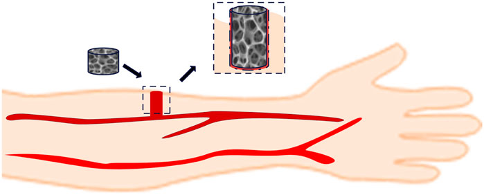
FIGURE 1. Changes in the form of functional hemostatic material.
In this paper, the actual area and length of a porous material in a fully expanded state are utilized to construct the physical model of multifunctional medical materials. Figure 2 shows the physical model of functional medical materials. The model in the figure will be used to simulate the process of blood penetration in functional medical materials. Among them, the circular cross-section material has a cross-sectional diameter of 10 mm, keeping the three shapes’ cross-sectional hydraulic diameter the same. The hydraulic diameter De expression is:
where f is the cross-sectional area of the flow channel; S is the wetted circumference of the flow channel. Moreover, due to Eq. (1), the edge length of the triangular section is 17.3 mm, the edge length of the square section is 10 mm, the length of the flow channel is 40 mm, and the center of the middle section shape of the three shapes of materials is point D.
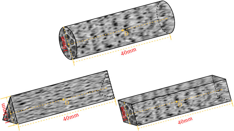
FIGURE 2. Circular, triangular and square section functional medical material flow channel.
In this paper, the porous media theory will be used to model the penetration of blood in functional hemostatic materials. Blood can be considered an incompressible fluid with constant density. Therefore, the equation for the conservation of mass of the fluid in the flow of porous hemostatic material is (Zhao et al., 2021):
where v is the flow velocity, and t is the time.
The body temperature will influence the thermal physical properties of blood, and the energy conservation equation should be calculated in the hemostatic process. For the problem of heat transfer between fluids in porous media, the energy equations for heat transfer between porous stopping materials and fluids need to be studied separately. The energy equations for porous materials and fluids are respectively (Zhao et al., 2021):
where δ is the porosity of the porous media. vz is the fluid axial flow velocity, and hsf is the heat transfer coefficient between the fluid and the material. Tf and Ts are the fluid and porous material temperatures, respectively. (ρcp)f and (ρcp)s are the heat capacities of the fluid and the porous material, respectively. λf and λs are the thermal conductivities of the fluid and the porous material, respectively.
In porous media, the equation for the conservation of momentum during fluid flow is (Zhao et al., 2021):
where Si is the momentum source term in the direction of i (i = x, y, z), consisting of a viscous loss term due to viscous drag and an inertial loss term due to inertial drag. In this simulation study, the standard fluid momentum equation’s resistance source term is modified to characterize the microscopic blocking effect of thrombus formation on blood within the functional hemostatic material. In the hemostasis process, the resistance to blood is mainly from the axial direction and the resistance source term is simplified as:
Considering the influence of change in blood viscosity and structural properties of porous material, the velocity of blood penetration into the functional hemostatic material is maximum at the beginning and then decreases due to thrombus generation. The maximum Reynolds number reached in the flow is less than 10, the flow is laminar, and the fluid in the porous media is subject to almost zero inertial resistance, the pressure drop is proportional to the velocity. As show Darcy’s law show (Ergun et al., 1949):
In this study, only the axial resistance of the fluid in the functional material is considered, so the momentum equation of Eq. (5) is simplified according to Eq. (8):
where μ is the dynamic viscosity of the fluid, and α is the permeability of the porous media. α characterizes the ability of a porous media to transport fluid and it depends on the viscous resistance of the fluid in the porous media, which is determined by the characteristics and size of the pore structure of the porous media, usually determined by experiment. For general porous media, α can be described using Ergon’s formula (Ergun et al., 1949):
where dp is the average diameter of the pores inside the material, the porosity δ describes the proportion of the pore volume inside the medium occupying the whole material volume, which is defined by:
In this study, blood is an incompressible non-Newtonian fluid which permeability is:
where n is the non-Newtonian fluid power law exponent, dimensionless. Due to the porous media filled with pores, in which the fluid flow distance cannot be considered as the distance between the two ends of the line, the fluid mass flow distance varies greatly. Therefore, the concept of tortuosity is introduced, which indicates the ratio of the actual distance of fluid flow in the porous media and the straight-line distance between the inlet and outlet ends. The tortuosity is given using Dhar Adhikari’s formula (Chen, 1999):
Combining Eqs. 9–14 describes the effect of the dynamic coagulation process on the flow resistance term.
Blood is a complex multiphase fluid. When the blood flow in the blood vessel shear rate is greater than 100 s−1, the shear force τ of blood and shear rate γ satisfy Newton’s law of shear:
In the study of thrombosis in functional hemostatic materials, blood penetrates with a small shear rate, conforms to some properties of non-Newtonian fluids, and can be considered a non-Newtonian fluid. For non-Newtonian fluids, the fluid’s dynamic viscosity no longer conforms to Newton’s law of shear. It cannot be regarded as a constant, but rather as a power-law relationship with the shear rate within a certain range. After statistical fitting of experimental data, the dynamic viscosity of blood can be given by the following power-law model (Neofytou, 2004):
By substituting the power-law model into Newton’s shear law and considering the effect of temperature on the kinetic viscosity, a correction term is introduced to obtain the power-law expression for the kinetic viscosity of a non-Newtonian fluid:
where k is the consistency coefficient of the fluid; T0 is the reference temperature, which is 310 K in this study, and T is the actual temperature of the blood.
During the coagulation process, the pore structure and material properties of functional hemostatic materials accelerate the aggregation of platelets in the pore channels, triggering the formation of thrombus obstruction in the tiny pores. With the action of thrombus adsorption factors of functional hemostatic materials, thrombus formation is unevenly distributed in the radial direction of the material. As blood penetrates, thrombus obstruction zones form and gradually develop from the boundaries. The overall pore volume gradually decreases, hindering blood penetration. Therefore, a boundary growth factor-based model of thrombus self-boundary formation development is proposed to characterize the microscopic hindrance process of thrombus growth in functional hemostatic materials, in which the power-law relationship between material porosity and blood permeation rate and infiltration time is:
where a is the thrombus adsorption factor determined by the physical properties of the porous functional hemostatic material, characterizing the thrombus blockage rate of different materials. b is the fitting parameter of the thrombus formation rate and the percolation rate when blood flows through the material, dimensionless. c is the boundary growth factor of the thrombus, describing the development rate of the thrombus from the boundary, and r is the distance of each part of the porous material from the material x-y cross-sectional shape center. The initial porosity of the porous hemostatic material is δ0. Substituting Eqs 18, 19 into Eq. (9) provides the resistance effect on blood flow caused by changes in porosity during coagulation.
This study uses the numerical simulation software Fluent to numerically calculate the process of thrombus development of blood-permeable functional hemostatic materials. The computational model uses the fully expanded porous material as shown in Figure 2. Figure 3 shows the x-y cross-sectional mesh of the three shape materials.
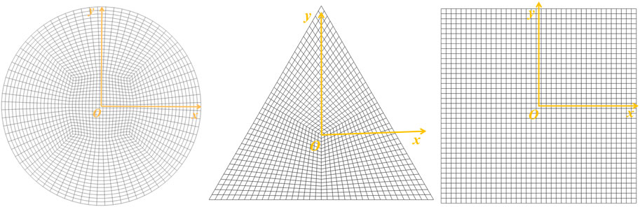
FIGURE 3. xy-plane calculation mesh (circle, triangle, square).
In the initial state, the functional hemostatic material is filled with air and blood penetrates into the porous material through the pressure inlet at the pressure of 12,000 Pa, while the thrombus starts to form and the outlet is the pressure outlet boundary condition with pressure of 0 Pa. The VOF multiphase flow model is used to distinguish blood from air, so the VOF stabilization method is turned on. The boundary condition of no-slip and impermeable is set at the wall of the calculation area. This simulation uses the laminar flow model for the viscous model and the physical velocity for the porous medium velocity format. The solution algorithm is the PISO algorithm with default under-relaxation factor, and the momentum is calculated with double precision in the second-order windward format.
Numerical simulations are preceded by verification of mesh independence to demonstrate that the results obtained from the simulations are independent of the mesh quality. In the study of this paper, the velocity and pressure distributions are calculated for each of the three shapes of functional materials using different numbers of meshes. Finalized with 73,000 cells for circular cross-section flow channels, 80,000 cells for triangular cross-section flow channels, and 60,000 cells for square cross-section flow channels.
In this study, the specific parameters used in the calculations are as follows (Zhao et al., 2019): ρ = 1,056 kg/m3, k = 0.01467 Pa∙sn, n = 0.7755, dp = 1.2 × 10⁻⁴ m, δ0 = 0.25, maintaining a constant temperature of T = 310 K, blood specific heat capacity cp = 850 J/(kg∙K), λf = 0.45 W/(m∙K). The values of a and b are different for functional hemostatic materials of different compositions. a = 8.0 × 10⁻⁴ m0.9∙s−1.1 and b = −0.1 were taken in this study. In this study, the transient calculation time steps were set to 0.1 s, and the number of iterations for each time step was 20.
The following analysis starts with an example of a material with a circular cross-section. Taking the y-z plane in the computational domain for research, Figure 4 shows the change in the volume fraction of blood and air for four moments, starting from the infiltration of blood into the functional hemostatic material and taking t = 0, 10, 20, 23.1 s. When the time is 0 s, the porous material is filled with air, and then the rate at which air is expelled decreases as blood penetrates. At t = 20 s, there is still a small amount of air at the exit of the porous material, at t = 23.1 s the air is completely expelled from the porous material and the blood completely fills the porous material.
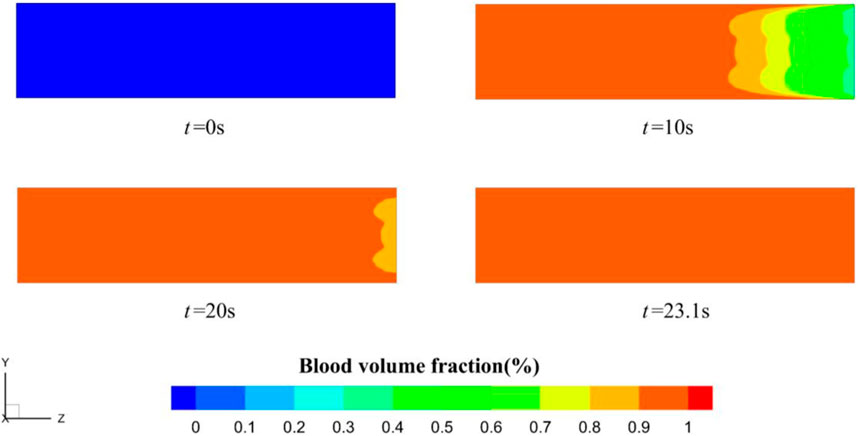
FIGURE 4. Blood volume fraction distribution (t = 0, 10, 20, 23.1 s).
As infiltration proceeds, the thrombus within the material gradually increases, the volume of the material pores decreases, the blood flow velocity gradually decreases, and eventually the blood stops infiltrating at 73.6 s. The stopping time is similar to the results obtained from the literature experiments (Zhao et al., 2019). That is, the proposed model is feasible and accurate for predicting the dynamic performance of functional medical materials. Figure 5 shows the z-directional velocity distribution of the porous material’s inlet, middle, and outlet cross-sections six moments before the blood flow cut-off, selected as t = 67, 68, 69, 70, 71, and 73.6 s. From the figure, there is a boundary layer near the wall of the flow channel, the blood in the boundary layer maintains a high flow velocity, and 67 s when the porous material near the location of the boundary layer flow velocity first reached 6 × 10⁻⁵ m/s, and the blood per second process reached the porous material pore size dp half, that the flow cut-off, the thrombus completely blocked its location pores.
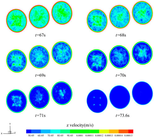
FIGURE 5. Flow velocity distribution of z-directional in a circular cross-section channel (t = 67, 68, 69, 70, 71, 73.6 s).
Figure 6 shows the porosity changes along the y-direction of the middle section of the functional hemostatic material, x = 0 mm, y = 0 (point D), 1, 2, 3, and 4 mm. The starting porosity at each location was 0.25. At the beginning of blood infiltration, the porosity at each site changed more slowly. With time increasing, the porosity change accelerated, and the further away from the central point, the porosity decreased rapidly. y = 4 mm location was completely blocked at 73.6 s, and the porosity decreased to 0. The porosity at point D in the center of the material was still around 0.09 at the cut-off point of the calculation. It can be found that during hemostasis, the thrombus formation is faster at the border than at the center, the thrombus gradually moves toward the center of the material as the blood penetrates, and thrombus formation accelerates with time.
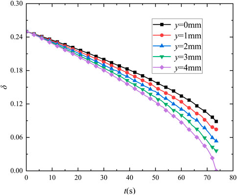
FIGURE 6. Porosity variation in the center of the porous material (y = 0, 1, 2, 3, 4 mm).
In order to investigate the effect of different inlet blood pressures on blood permeation, circular cross-section materials were selected for comparative analysis for the other working conditions with inlet pressures of 8,000 Pa and 16,000 Pa. Figure 7 shows the blood flow velocity at point D in the center of the porous hemostatic material at different inlet pressure. The change of flow velocity was fast at the initial moment, and the rate of change gradually leveled off as the infiltration proceeded. At 16,000 Pa, the blood flow velocity is the slowest and cuts off at 76.0 s, and the penetration cutoff time is 3.3% slower than that at an inlet pressure of 12,000 Pa. And at 8,000 Pa, the blood flow velocity was the fastest and was cut off at 69.4 s, and the penetration cutoff time was 5.7% faster than that at an inlet pressure of 12,000 Pa. It can be found that the blood inlet pressure has a greater influence on the blood permeation cut-off time, the lower the inlet pressure, the slower the flow velocity, which is favorable for thrombus adsorption, and the faster the cut-off time.
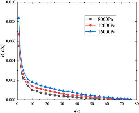
FIGURE 7. Flow velocity at point D with different inlet pressure.
Different utilization scenarios and environmental temperatures can impact the performance of porous hemostatic materials. Therefore, we further analyzed the effect of heat transfer characteristics of functional hemostatic materials on their performance. Different external temperatures affect the heat transfer between the blood and the functional hemostatic material, which in turn affects the viscosity of the blood. The higher the temperature of the blood, the lower its viscosity. The effect on the performance of porous functional hemostatic materials at different external ambient temperatures was obtained by calculating the energy conservation equation in the coagulation process. The inlet temperature of blood was set at 310 K. The wall temperatures of 280 K, 310 K, and 330 K were taken for comparative analysis. Figure 8 shows the blood flow velocity at point D in the center of the porous hemostatic material at different wall temperatures, with similar changes in flow velocity for the three temperature operating conditions. The highest flow velocity was observed at 330 K and the lowest at 280 K. The difference in flow velocity decreased for the three temperature conditions, and the final calculated cut-off times were similar, with the final cut-off times varying within 0.5 s. It can be found that temperature variations have little effect on the blood coagulation process.
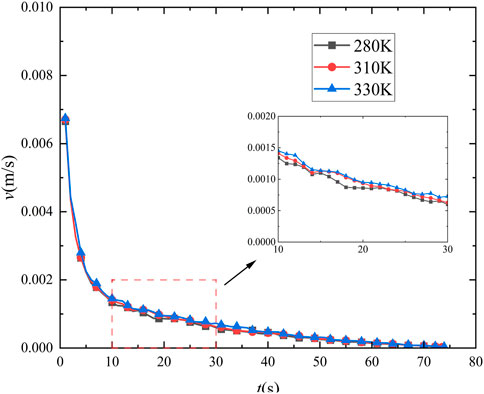
FIGURE 8. Flow velocity at point D with different wall temperatures.
The cut-off time for blood flow within the functional hemostatic material varies considerably between different cross-sectional shapes. Figure 9 shows the variation in flow velocity at point D in the center of the selected circular, triangular, and square cross-sectional flow channels. The variation of velocity at point D in the center of the three cross-sectional shapes remained the same, with the flow velocity of the circular channel being faster than that of the triangular and square channel at the initial moment. As infiltration proceeds, the rate of change of flow velocity gradually tends to level off, and the calculated cut-off time varies greatly. The average flow velocity of the triangular channel was the smallest, and its infiltration cut-off time is the shortest, 69.4 s, which 5.7% faster than that of the circular channel. The square channel was 71.2 s, which was 3.3% faster than that of the circular channel.
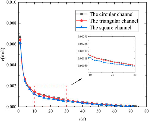
FIGURE 9. Flow velocity at point D in flow channels with different cross-sectional shapes.
Moreover, Figures 10, 11 show the z-directional flow velocity distributions for the inlet, middle, and outlet sections of the triangular and square cross-section flow channels at the six moments before the cut-off. The velocity trends in the triangular and square cross-sectional channels are similar to those in the circular channel, and there are boundary layers with high velocities. The flow velocity decreases fastest near the boundary layer, and the low flow velocity region develops towards the center of the material. Eventually, the blood flow path per second in most areas of the material decreases to half the calculated cut-off of the pore dp, blood infiltration is blocked. With Figures 9–11, it can be observed that changing the shape of the cross-section can change the rate of blood coagulation, with smaller flow favoring thrombus development.
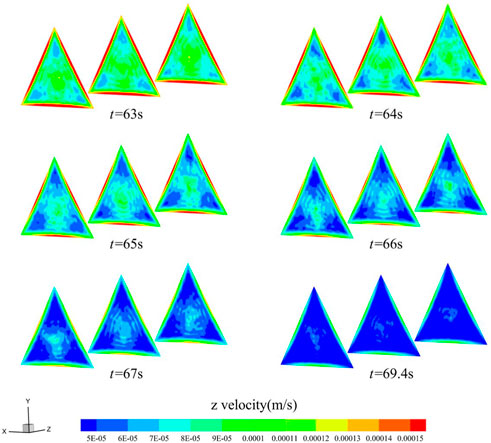
FIGURE 10. Distribution of z-directional flow velocity of blood in the triangular cross-section channel (t = 63, 64, 65, 66, 67, 69.4 s).
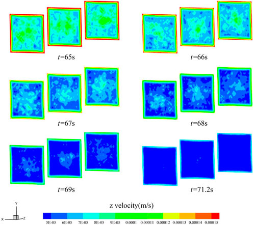
FIGURE 11. Distribution of z-directional flow velocity of blood in the square cross-section channel (t = 65, 66, 67, 68, 69, 71.2 s).
To further consider the influence of material flow channel shape factors on blood infiltration and thrombus formation, the gradually expanding channel with an inlet cross-section diameter of 10 mm and an outlet cross-section diameter of 12 mm, and the gradually shrinking channel with an inlet cross-section diameter of 10 mm and an outlet cross-section diameter of 8 mm were selected for comparative analysis by keeping a circular cross-section. After verifying the independence of the mesh, Figure 12 shows the z-directional flow velocity trends in the center of the material in the circular channel, the gradually expanding channel, and the gradually shrinking channel. The z-directional flow velocities in the centers of the three remain similar, with the highest flow velocity in the center of the gradually expanding channel and the lowest in the center of the gradually shrinking channel at the beginning of blood infiltration, and the difference in z-directional flow velocities between the three decreases gradually as the flow proceeds. Between the three, the gradually expanding channel with the smallest average flow velocity at the outlet section has the shortest cut-off time of 71.6 s, which is 2.7% faster than the permeation cut-off time of the circular uniform flow channel, while the cut-off time of the gradually decreasing channel is 72.1 s, which is 2.0% faster than the permeation cut-off time of the circular uniform flow channel. By way of comparison, it can be seen that the outlet cross-section, whether enlarged or reduced, will accelerate coagulation during blood penetration.
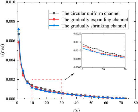
FIGURE 12. Flow velocity at point D for different channels.
Figure 13 and Figure 14 show the z-directional flow velocity distributions for the inlet, middle, and outlet cross-sections of the gradually expanding and gradually shrinking channels, calculated for the six moments before the cut-off. For both the gradually expanding and gradually shrinking channels, the change in flow velocity in the small diameter section lags behind the large diameter section. The larger the diameter section, the faster the z-directional flow velocity decreases. The smaller the diameter section, the slower the z-directional flow velocity decreases. When the flow velocity is below 6 × 10⁻⁵ m/s in most areas within the material, the calculation is cut-off, and the blood stops flowing. Analysis reveals that, the larger the cross-sectional area in the material flow path, the faster the thrombus grows. By setting the cross-section shape change relationship rationally, it will improve the coagulation condition in blood permeation.
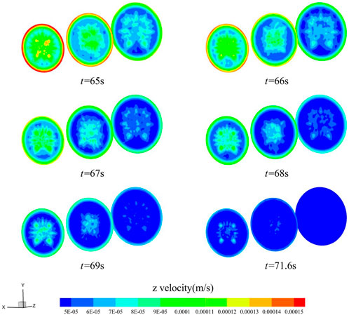
FIGURE 13. Distribution of z-directional flow velocity of blood in the gradually expanding channel (t = 65, 66, 67, 68, 69, 71.6 s).
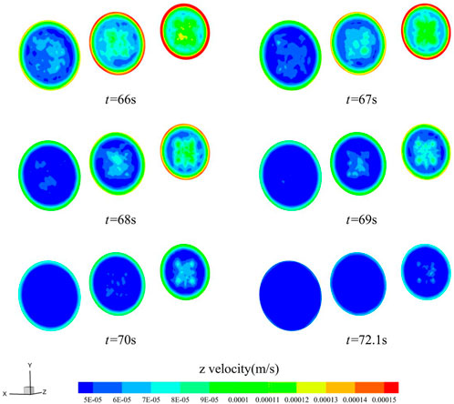
FIGURE 14. Distribution of z-directional flow velocity of blood in the gradually shrinking channel (t = 66, 67, 68, 69, 70, 72.1 s).
In this paper, based on the theory of porous media and non-Newtonian fluid properties, combined with experimental research, the study proposes for the first time a thrombus boundary growth factor in the process of blood coagulation, and constructs a physical model for the evolution of microscopic obstruction of thrombus boundary growth of blood in porous hemostatic materials. The dynamic evolution of the blood coagulation process in a circular cross-section hemostatic material has been analyzed by CFD, focusing on the comparison of the differences in the microscopic obstruction process of blood with different inlet pressures, external temperatures and shape factors. Provides theoretical support for the study on the variation of physical processes of blood coagulation in porous functional hemostatic materials. The specific findings of this manuscript study are as follows:
1. After the blood enters the functional hemostatic material, the thrombus starts to form from the boundary of the flow channel and gradually advances to the center of the material until most of the porous material is blocked by the thrombus, and the material porosity, permeability and blood flow velocity tend to be close to zero;
2. For different blood inlet pressure, smaller inlet pressure, favorable with thrombus adsorption and growth;
3. The higher the temperature the lower the blood viscosity, but the effect on the velocity of blood coagulation in functional hemostatic materials was minimal;
4. Among the functional hemostatic materials with different cross-sectional shapes, the lower the blood flow velocity, the more favorable the blood coagulation, and in the comparison of cross-sectional shapes with the same hydraulic radius, the triangular cross-section has the fastest cut-off time for blood flow;
5. Among the functional hemostatic materials with different flow channel shape factors, the blood coagulates faster in the cross section with larger area in the flow channel, and the reasonable arrangement of the flow channel shape of the functional hemostatic materials can coagulate blood faster.
The research in this paper focuses on the effects of changes in external physical conditions and material shape on blood coagulation as blood flows through functional hemostatic materials. There are lacks of analysis of the effect of the physical properties of the material on blood coagulation and the possible biochemical reactions of the material with blood are not addressed. In future studies, the effects of material physical properties and biochemical reactions on blood coagulation in functional hemostatic materials should be considered.
The original contributions presented in the study are included in the article/Supplementary material, further inquiries can be directed to the corresponding author.
JH: Conceptualization, Funding acquisition, Methodology, Project administration, Supervision, Writing–original draft. XW: Data curation, Formal Analysis, Investigation, Software, Validation, Writing–original draft. TM: Investigation, Methodology, Software, Writing–original draft. CJ: Data curation, Formal Analysis, Investigation, Methodology, Writing–review and editing. TH: Investigation, Methodology, Software, Validation, Writing–original draft, Writing–review and editing. WL: Conceptualization, Formal Analysis, Investigation, Methodology, Project administration, Writing–original draft, Writing–review and editing.
The author(s) declare financial support was received for the research, authorship, and/or publication of this article. The study was supported by the Innovation Science Foundation of Chinese People’s Liberation Army General Hospital (No. 22QNCZ006 and No. QZX-2023-2).
The authors declare that the research was conducted in the absence of any commercial or financial relationships that could be construed as a potential conflict of interest.
All claims expressed in this article are solely those of the authors and do not necessarily represent those of their affiliated organizations, or those of the publisher, the editors and the reviewers. Any product that may be evaluated in this article, or claim that may be made by its manufacturer, is not guaranteed or endorsed by the publisher.
Aminpour, M., Montemagno, C., and Tuszynski, J. A. (2019). An overview of molecular modeling for drug discovery with specific illustrative examples of applications. Molecules 24, 1693. doi:10.3390/molecules24091693
Carné-SáNCHEZ, A., Carmona, F. J., Kim, C., and Furukawa, S. (2020). Porous materials as carriers of gasotransmitters towards gas biology and therapeutic applications. Chem. Commun. 56, 9750–9766. doi:10.1039/d0cc03740k
Chan, L. W., Kim, C. H., Wang, X., Pun, S. H., White, N. J., and Kim, T. H. (2016). PolySTAT-modified chitosan gauzes for improved hemostasis in external hemorrhage. Acta Biomater. 31, 178–185. doi:10.1016/j.actbio.2015.11.017
Chen, G. (1999). Computational studies of forced convection of Newtonian and non-Newtonian fluids in porous media: application to heat transfer enhancement. Stevens Inst. Technol.
Chen, J., Chen, S., Cheng, W., Lin, J., Hou, S., Liu, H., et al. (2019). Fabrication of porous starch microspheres by electrostatic spray and supercritical CO2 and its hemostatic performance. Int. J. Biol. Macromol. 123, 1–9. doi:10.1016/j.ijbiomac.2018.10.219
Deineka, V., Sulaieva, O., Pernakov, N., Radwan-Pragłowska, J., Janus, L., Korniienko, V., et al. (2021). Hemostatic performance and biocompatibility of chitosan-based agents in experimental parenchymal bleeding. Mater. Sci. Eng. C 120, 111740. doi:10.1016/j.msec.2020.111740
Dong, Q., Li, Y., Jiang, H., Zhou, X., Liu, H., Lu, M., et al. (2021). 3D-cubic interconnected porous Mg-based scaffolds for bone repair. J. Magnesium Alloys 9, 1329–1338. doi:10.1016/j.jma.2020.05.022
Dubbeldam, D., and Snurr, R. (2007). Recent developments in the molecular modeling of diffusion in nanoporous materials. Mol. Simul. 33, 305–325. doi:10.1080/08927020601156418
Ergun, S., Orning, A. A. J. I., and Chemistry, E. (1949). Fluid flow through randomly packed columns and fluidized beds. Industrial Eng. Chem. 41, 1179–1184. doi:10.1021/ie50474a011
Eslami, M., Nikkhah, S. J., Hashemianzadeh, S. M., and Sajadi, S. A. S. (2016). The compatibility of tacrine molecule with poly (n-butylcyanoacrylate) and chitosan as efficient carriers for drug delivery: a molecular dynamics study. Eur. J. Pharm. Sci. 82, 79–85. doi:10.1016/j.ejps.2015.11.014
Franca, E. F., Freitas, L. C., and Lins, R. D. (2011). Chitosan molecular structure as a function of N-acetylation. Biopolymers 95, 448–460. doi:10.1002/bip.21602
Gao, H., Zhong, Z., Xia, H., Hu, Q., Ye, Q., Wang, Y., et al. (2019). Construction of cellulose nanofibers/quaternized chitin/organic rectorite composites and their application as wound dressing materials. Biomaterials Sci. 7, 2571–2581. doi:10.1039/c9bm00288j
Geesala, R., Bar, N., Dhoke, N. R., Basak, P., and Das, A. (2016). Porous polymer scaffold for on-site delivery of stem cells–protects from oxidative stress and potentiates wound tissue repair. Biomaterials 77, 1–13. doi:10.1016/j.biomaterials.2015.11.003
Hassan, B., Rajan, V. K., Mujeeb, V. A., and Muraleedharan, K. (2017). A DFT based analysis of adsorption of Hg2+ ion on chitosan monomer and its citralidene and salicylidene derivatives: prior to the removal of Hg toxicity. Int. J. Biol. Macromol. 99, 549–554. doi:10.1016/j.ijbiomac.2017.03.032
Hernandez, J. L., and Woodrow, K. A. (2022). Medical applications of porous biomaterials: features of porosity and tissue-specific implications for biocompatibility. Adv. Healthc. Mater. 11, 2102087. doi:10.1002/adhm.202102087
He, Y., Liu, K., Zhang, C., Guo, S., Chang, R., Guan, F., et al. (2022). Facile preparation of PVA hydrogels with adhesive, self-healing, antimicrobial, and on-demand removable capabilities for rapid hemostasis. Biomaterials Sci. 10, 5620–5633. doi:10.1039/d2bm00891b
Hill, S. J., Young, A., Prendergast, B., Redwood, S., Rajani, R., and De Vecchi, A. (2022). Patient-specific fluid simulation of transcatheter mitral valve replacement in mitral annulus calcification. Front. Cardiovasc. Med. 9, 934305. doi:10.3389/fcvm.2022.934305
Katsoulidis, A. P., Antypov, D., Whitehead, G. F., Carrington, E. J., Adams, D. J., Berry, N. G., et al. (2019). Chemical control of structure and guest uptake by a conformationally mobile porous material. Nature 565, 213–217. doi:10.1038/s41586-018-0820-9
Khezri, A., Karimi, A., Yazdian, F., Jokar, M., Mofradnia, S. R., Rashedi, H., et al. (2018). Molecular dynamic of curcumin/chitosan interaction using a computational molecular approach: emphasis on biofilm reduction. Int. J. Biol. Macromol. 114, 972–978. doi:10.1016/j.ijbiomac.2018.03.100
Koumentakou, I., Terzopoulou, Z., Michopoulou, A., Kalafatakis, I., Theodorakis, K., Tzetzis, D., et al. (2020). Chitosan dressings containing inorganic additives and levofloxacin as potential wound care products with enhanced hemostatic properties. Int. J. Biol. Macromol. 162, 693–703. doi:10.1016/j.ijbiomac.2020.06.187
Ksenofontova, O., Vasin, A., Egorov, V., Bobyl’, A., Soldatenkov, F. Y., Terukov, E., et al. (2014). Porous silicon and its applications in biology and medicine. Tech. Phys. 59, 66–77. doi:10.1134/s1063784214010083
Liu, J.-Y., Li, Y., Hu, Y., Cheng, G., Ye, E., Shen, C., et al. (2018). Hemostatic porous sponges of cross-linked hyaluronic acid/cationized dextran by one self-foaming process. Front. Cardiovasc. Med. 83, 160–168. doi:10.1016/j.msec.2017.10.007
Marfin, Y., Solomonov, V., Timin, S., and V Rumyantsev, E. (2017). Recent advances of individual BODIPY and BODIPY-based functional materials in medical diagnostics and treatment. Curr. Med. Chem. 24, 2745–2772. doi:10.2174/0929867324666170601092327
Mi, H.-Y., Jing, X., and Turng, L.-S. (2015). Fabrication of porous synthetic polymer scaffolds for tissue engineering. J. Cell. Plastics 51, 165–196. doi:10.1177/0021955x14531002
Moghimi, S. M., and Hunter, A. C. (2000). Poloxamers and poloxamines in nanoparticle engineering and experimental medicine. Trends Biotechnol. 18, 412–420. doi:10.1016/s0167-7799(00)01485-2
Neofytou, P. (2004). Comparison of blood rheological models for physiological flow simulation. Biorheology 41, 693–714.
Pan, M., Tang, Z., Tu, J., Wang, Z., Chen, Q., Xiao, R., et al. (2018). Porous chitosan microspheres containing zinc ion for enhanced thrombosis and hemostasis. Mater. Sci. Eng. C 85, 27–36. doi:10.1016/j.msec.2017.12.015
Rashidi, S., Esfahani, J. A., and Karimi, N. (2018). Porous materials in building energy technologies—a review of the applications, modelling and experiments. Renew. Sustain. Energy Rev. 91, 229–247. doi:10.1016/j.rser.2018.03.092
Rashidi, S., Esfahani, J. A., and Rashidi, A. (2017). A review on the applications of porous materials in solar energy systems. Renew. Sustain. Energy Rev. 73, 1198–1210. doi:10.1016/j.rser.2017.02.028
Shao, G., Hanaor, D. A., Shen, X., and Gurlo, A. (2020). Freeze casting: from low-dimensional building blocks to aligned porous structures—a review of novel materials, methods, and applications. Adv. Mater. 32, 1907176. doi:10.1002/adma.201907176
Song, H.-F., Chen, A.-Z., Wang, S.-B., Kang, Y.-Q., Ye, S.-F., Liu, Y.-G., et al. (2014). Preparation of chitosan-based hemostatic sponges by supercritical fluid technology. Materials 7, 2459–2473. doi:10.3390/ma7042459
Sousa, C. P., De Oliveira, R. C., Freire, T. M., Fechine, P. B., Salvador, M. A., Homem-De-Mello, P., et al. (2017). Chlorhexidine digluconate on chitosan-magnetic iron oxide nanoparticles modified electrode: electroanalysis and mechanistic insights by computational simulations. Sensors Actuators B Chem. 240, 417–425. doi:10.1016/j.snb.2016.08.181
Srinivasu, P. N., Bhoi, A. K., Jhaveri, R. H., Reddy, G. T., and Bilal, M. (2021). Probabilistic Deep Q Network for real-time path planning in censorious robotic procedures using force sensors. J. Real-Time Image Process. 18, 1773–1785. doi:10.1007/s11554-021-01122-x
Sun, Z., and Chaichana, T. (2010). Fenestrated stent graft repair of abdominal aortic aneurysm: hemodynamic analysis of the effect of fenestrated stents on the renal arteries. Korean J. radiology 11, 95–106. doi:10.3348/kjr.2010.11.1.95
Swanson, W. B., and Ma, P. X. (2020). Textured and porous biomaterials. Biomaterials Sci., 601–622. doi:10.1016/b978-0-12-816137-1.00039-8
Tsereteli, L., and GrafmüLLER, A. (2017). An accurate coarse-grained model for chitosan polysaccharides in aqueous solution. PLoS One 12, e0180938. doi:10.1371/journal.pone.0180938
Wang, X., Lin, Q., Pan, H., Jia, S., Wu, H., Shi, Y., et al. (2020a). Oxidation modification of chitosan-based mesoporous carbon by soft template method and the adsorption and release properties of hydroxycamptothecin. Sci. Rep. 10, 15772. doi:10.1038/s41598-020-72933-4
Wang, Y., Liu, G., Wu, L., Qu, H., Song, D., Huang, H., et al. (2020b). Rational design of porous starch/hyaluronic acid composites for hemostasis. Int. J. Biol. Macromol. 158, 1319–1329. doi:10.1016/j.ijbiomac.2020.05.018
Wu, L., Li, Y., Fu, Z., and Su, B.-L. (2020). Hierarchically structured porous materials: synthesis strategies and applications in energy storage. Natl. Sci. Rev. 7, 1667–1701. doi:10.1093/nsr/nwaa183
Yang, X., Liu, W., Li, N., Wang, M., Liang, B., Ullah, I., et al. (2017). Design and development of polysaccharide hemostatic materials and their hemostatic mechanism. Biomaterials Sci. 5, 2357–2368. doi:10.1039/c7bm00554g
Yun, T., Weihua, L., and Yayun, S. (2013). Computer molecular modeling: a brief introduction to the Nobel Prize in chemistry 2013. Chin. J. Nat. 35, 408–415.
Yu, P., and Zhong, W. (2021). Hemostatic materials in wound care. Burns Trauma 9, tkab019. doi:10.1093/burnst/tkab019
Zhao, Y.-F., Zhao, J.-Y., Hu, W.-Z., Ma, K., Chao, Y., Sun, P.-J., et al. (2019). Synthetic poly (vinyl alcohol)–chitosan as a new type of highly efficient hemostatic sponge with blood-triggered swelling and high biocompatibility. J. Mater. Chem. B 7, 1855–1866. doi:10.1039/c8tb03181a
Zhao, Y., Hao, J., Chen, Z., Li, M., Ren, J., and Fu, X. (2021). Blood-clotting model and simulation analysis of polyvinyl alcohol-chitosan composite hemostatic materials. J. Mater. Chem. B 9, 5465–5475. doi:10.1039/d1tb00159k
Zheng, C., Zeng, Q., Pimpi, S., Wu, W., Han, K., Dong, K., et al. (2020). Research status and development potential of composite hemostatic materials. J. Mater. Chem. B 8, 5395–5410. doi:10.1039/d0tb00906g
Keywords: functional medical material, non-Newtonian fluid, boundary growth model, microscopic blockage, numerical simulation
Citation: Hao J, Wu X, Ma T, Ju C, Hao T and Li W (2024) A new boundary growth model for the analysis of microscopic blockage and various cross-section shapes effects in porous functional medical material. Front. Mater. 10:1324106. doi: 10.3389/fmats.2023.1324106
Received: 22 October 2023; Accepted: 20 December 2023;
Published: 08 January 2024.
Edited by:
Marcin Wozniak, Silesian University of Technology, PolandReviewed by:
Parvathaneni Naga Srinivasu, Prasad V. Potluri Siddhartha Institute of Technology, IndiaCopyright © 2024 Hao, Wu, Ma, Ju, Hao and Li. This is an open-access article distributed under the terms of the Creative Commons Attribution License (CC BY). The use, distribution or reproduction in other forums is permitted, provided the original author(s) and the copyright owner(s) are credited and that the original publication in this journal is cited, in accordance with accepted academic practice. No use, distribution or reproduction is permitted which does not comply with these terms.
*Correspondence: Wenchao Li, bGl3ZW5jaGFvMzAxQDE2My5jb20=
Disclaimer: All claims expressed in this article are solely those of the authors and do not necessarily represent those of their affiliated organizations, or those of the publisher, the editors and the reviewers. Any product that may be evaluated in this article or claim that may be made by its manufacturer is not guaranteed or endorsed by the publisher.
Research integrity at Frontiers
Learn more about the work of our research integrity team to safeguard the quality of each article we publish.