 Shaorui Wang1,2
 Ji Feng
 Ligui Yang
94% of researchers rate our articles as excellent or good
Learn more about the work of our research integrity team to safeguard the quality of each article we publish.
Find out more
ORIGINAL RESEARCH article
Front. Mater. , 06 February 2024
Sec. Structural Materials
Volume 10 - 2023 | https://doi.org/10.3389/fmats.2023.1321177
This article is part of the Research Topic Recent Advances in Durability Improvement and Low-Carbon Strategy of Engineering Materials and Structures View all 17 articles
Achieving full equilibrium for the horizontal component force of the backstay in cable-stayed arch bridges is challenging, and the stiffness of the buckle tower has a notable influence on the overall shape of the main arch structure. Increased stiffness in the buckle tower leads to reduced construction complexity. Therefore, this study proposed a method of enhancing the longitudinal thrust stiffness of the buckle tower using the joint effect of approach bridges. A sensitivity analysis was conducted on the approach bridge–composite buckle tower structure to determine the optimal combination method, resulting in the formulation of an analytical expression for the thrust stiffness of this structure. In this study, numerical analysis was performed to explore the composition mechanism of the thrust stiffness influenced by the pier–girder connection, and we discussed the applicability of the joint effect of approach bridges during the cantilever assembly process of arch ribs. The following conclusions were obtained: 1) prior to installing the main girder of the approach bridge, when the steel buckle tower and the junction pier have already been secured, the most effective approach is to form a “T” rigid structure by firmly connecting the main girder of the approach bridge with the composite buckle tower. This configuration provides self-weight deflection and pier–girder rotation restriction effects. 2) The study presents analytical formulas for the completely rigid pier–girder connection of the approach bridge–composite buckle tower structure, partially rigid pier–girder connection, and pre-deviation. Combined with the calculation program, this can guide structural design. 3) When a large downward elevation error of the arch ribs occurs in the middle and later stages, the cable force needed to install new arch segments becomes overly large. Therefore, the joint effect of approach bridges can be utilized to substitute for a portion of the cable force, effectively reducing potential elevation errors that might arise in subsequent arch ribs in the absence of this joint effect.
Cable-stayed suspension is the most common construction method for large-span arch bridges (Liu, 2008; Ding et al., 2023). During the cable-stayed suspension construction of arch bridges, due to installation or manufacturing errors and dynamic changes in the construction process, the horizontal component force of buckle anchor cables faces difficulties in reaching equilibrium, causing the buckle tower to deviate in the longitudinal direction of the bridge (Zhou et al., 2000b; Xu et al., 2016a). Moreover, once the control points of the cable-stayed construction arch rib reach the design elevation, buckle backstay anchoring is no longer tensioned. When there is a deviation in the shape of the arch rib, making subsequent adjustments can become a complicated or even impossible task (Xu et al., 2016b; Chen et al., 2023). Therefore, the buckle tower stiffness significantly impacts the line shape of the main arch ring. Increased stiffness in the buckle tower not only reduces construction complexity but also enhances the construction quality of the main arch. Under the same conditions, the stiffness of the buckle tower should be increased as much as possible to reduce the tower deviation. Currently, owing to the widespread use of the cable-stayed suspension method in building large-span arch bridges, various researchers have undertaken extensive research to manage and optimize the line shape of the cable-stayed construction arch rib.
Zheng et al. (1996) utilized the principle of torque equilibrium to calculate the cable force on the arch rib during the cable-stayed hoisting construction, resulting in promising results when this method was used to compute the hinge joint conditions between arch segments. Subsequently, Zhou et al. (2000a) delved deeper into the torque equilibrium method, introducing the “zero bending moment method.” By utilizing integral calculations, they enhanced the accuracy of determining the cable force on the arch rib. Subsequently, Zhou (2002) introduced the fixed-length buckle cable technique. This approach considered both the elastic elongation of the buckle cable and the deflection due to the self-weight of the arch segment during the hoisting process, thereby aligning the arch rib with the design arch axis. However, this method necessitated the tensioning of the buckle cable all at once, posing challenges for subsequent adjustments if discrepancies arose between the calculated and actual results. Qin (2003; 2008) introduced the stress-free state method, revealing that if the structural system, stress-free state quantities, boundaries, and external loads of the bridge being constructed in segmented main arch rings were maintained, the internal forces and displacements of the completed bridge structure had a unique solution. Interestingly, this was irrespective of the construction sequence. Subsequently, Wang (2013) suggested that the stress-free state method could eliminate the impact of temperature effects and tower deviation on the arch rib’s line shape during hoisting. Hao and Gu (2015) noted that the practice of inserting gaskets between flanges to compensate for bending angles when controlling the hoisting of steel pipe arch ribs using the pre-elevation method would alter the stress-free state quantity of the arch rib. Consequently, error in the line shape and internal forces after closure was inevitable. Studying the causes of errors and their transfer mechanism during the hoisting of steel pipe arch ribs, Hao et al. (2018) utilized the stress-free state method to analyze the construction process of the arch rib and proposed several adjustable error control intervals. Focusing on the error in the hoisting and splicing of the arch rib, Zhang (2001) was the first to introduce the optimization theory into the calculation of cable forces. Combined with the Kalman filter method, he calculated the optimal cable force matrix and the preliminary arch degree during the bridge construction process. Subsequently, Zhang et al. (2004) integrated ANSYS finite element software with the optimization theory to calculate variations in cable forces, thereby addressing the requirement for an accurate adjustment of cable forces during the line shape adjustment process. Xu (2011) used the Bayesian temperature prediction model to discern the pattern of seasonal temperature changes on the installation line shape of the arch rib. He then used the influence matrix and optimization algorithms to adjust the errors caused by the temperature during the splicing process of the arch rib. Hao and Gu (2016) also studied the line shape adjustment issue during the splicing and hoisting processes of the arch rib. Considering the deviation between the real and design line shapes of the arch rib, they proposed a theoretical calculation method for a “feasible optimal solution” based on the influence matrix. Using the stress equilibrium equation considering only the tensile stress, permissible tensile stress of the arch rib, and the influence matrix method, Liu et al. (2022) put forward an initial buckle cable force calculation method based on the stress equilibrium method. This improvement on the original stress equilibrium method resulted in a significant increase in work efficiency. Finally, using the influence matrix and linear programming to determine the initial value of iterative cable forces, Li et al. (2017) observed that appropriate cable forces, installed forward through the golden selection method and iterations, achieved a one-time tension of the cable force for cable-stayed steel pipe concrete arch bridges tailored to the installation shape.
Long (2012) discovered that the key to the integrated construction of cable towers and buckle towers was to control the displacement at the tower top. This approach guaranteed that the cable tower and buckle tower could withstand smaller bending moments. To control this displacement, it is essential to minimize the horizontal forces caused by hoisting arch ribs and tensioning buckle cables. Deng et al. (2020) used the suspension element method to derive the calculation formula for the tower deviation of the cable-stayed system with a push-down cable set. This achieved effective integration and unification of the computations during the cable-stayed construction stage and tower deviation calculation, which is extremely important for accurate control of tower deviation. Deng (2009) used geometric analysis to derive the calculation formula for the influence of buckle tower deviation on the elevation of arch rib segments. This provides a valuable reference for the design of cable-stayed hoisting and the control of segment installation elevation. Mo (2021) studied the impact of main cable slippage on tower deviation in the cable-stayed hoisting system design. He observed that the main cable slippage significantly affected the cable-stayed hoisting system, leading to noticeable changes in top tower displacement and top tower stress.
Regarding the study of line shape control in the construction of cable-stayed arch ribs, adjustments for various errors affecting the accuracy of the arch rib line shape are mainly based on buckle cable force calculations (Gu et al., 2015). However, there remains a dearth of research dedicated to the control of tower deviations by improving the longitudinal thrust stiffness of the buckle tower. Furthermore, there is a notable absence of studies examining the mechanism behind thrust stiffness formation, taking into account factors like self-weight deflection and local deformation effects in approach bridge–composite buckle tower structures. Therefore, this paper uses a large-span deck-type steel pipe concrete arch bridge built through a cable-stayed cantilever assembly as the engineering background. The study then delves into the calculation techniques and investigates the effects of buckle tower stiffness, considering the joint effect of approach bridges.
The construction of a cable-stayed arch bridge requires the erection of a temporary buckle tower to complete the tensioning of the buckle anchor cable. For the construction of arch bridges with restricted construction sites and larger rise-to-span ratios, a combination of permanent and temporary structures, i.e., a composite cable tower, is generally adopted. This involves erecting a steel buckle tower on juncture piers, allowing both the juncture pier and steel buckle tower to jointly withstand the horizontal thrust caused by the pull cable (Chen et al., 2017). Depending on the dimensions of the juncture pier along the longitudinal direction of the bridge, the steel buckle tower may either pass through the main girder of the approach bridge via a wet joint or not pass through it at all (Figure 1). However, the main paths of force transmission between the components in both cases do not differ.
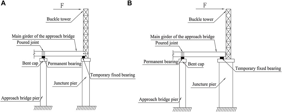
FIGURE 1. Schematic diagram of the synergistic effect of the buckle tower and the approach bridge. (A) Passing through the main girder. (B) Without passing through the main girder.
As shown in Figure 2, the steel buckle tower is consolidated to the juncture pier. The increased overall height results in increased flexibility of the entire structure. During construction, significant deflection deformations occur due to differences in horizontal cable forces, which, in turn, cause significant deviations in the buckle tower in the longitudinal direction of the bridge (Yu, 2018).
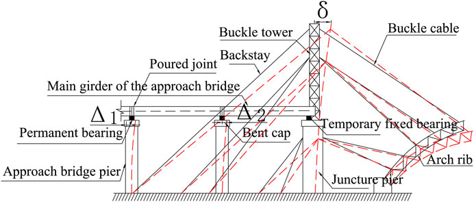
FIGURE 2. Schematic diagram of the buckle tower deflection-induced deviation.
This paper aims to enhance the longitudinal thrust stiffness of the composite buckle tower by harnessing the joint effect of approach bridges. The core concept is to facilitate cooperative support among the buckle tower, juncture pier, approach bridge piers, and main girder of the approach bridge, thereby controlling buckle tower deviations.
The main bridge and approach bridge juncture piers use a “gate”-type hollow thin-walled pier with a variable box cross section. The center distance of the two lateral limbs of the pier is the same width as the main arch rib, 16.0 m, and the material is C50. It is 89.9 m high (91.9 m including the bent cap). The cross-sectional size of a single-limb pier is 5.5 m in the transverse direction of the bridge and 6.5 m in the longitudinal direction, with the internal wall thickness varying from 60 to 80 cm. The steel buckle tower, 31.19 m high, is made of Q345 material and is a truss structure composed of columns, connecting horizontal bars, and diagonal bars. The columns use φ630 × 20 mm steel pipes, and the horizontal and diagonal bars use φ325 × 10 mm and φ273 × 8 mm steel pipes, respectively. All bar members are connected by welding. There are two truss cross braces between the two limbs of the steel buckle tower, and the steel buckle tower is anchored on the top of the juncture pier. The approach bridge piers are set as thin-walled double-limb piers with a height of 90.1 m. The cross-sectional size is 2.5 m × 2.0 m, the thickness is 40 cm, and the material is C35. The two piers are connected by two inter-column tie beams. The material of the main girder of the approach bridge is C50, with each 42.0 m span divided into 9 T girders. The overall effect of the model is illustrated in Figure 3. The model was created using Midas/Civil finite-element software.
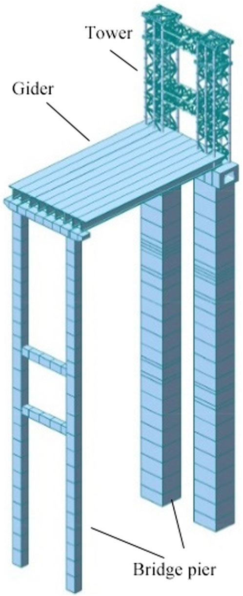
FIGURE 3. Midas/Civil model of the tower and approach bridge.
This study examines the effects of external factors on the thrust stiffness of the composite buckle tower. Therefore, the size of the horizontal cable force difference is determined using only the situation with the composite buckle tower. According to the theory of thrust stiffness, the thrust stiffness of the series structure is only related to the flexural stiffness EI and height h and is independent of the external load of the system. Therefore, horizontal loads can be exclusively applied at the top of the composite buckle tower to represent the horizontal cable force difference.
To keep the deformation of the structure within the range of linear elasticity and make the research more reasonable, the size of the horizontal cable force difference should be set based on relevant specifications.
According to the specification JTG/T 3650, 2020, the tower deviation with the fixed foot is H/400–H/600, where H is the height of the steel buckle tower. Considering that the height of the juncture pier increases the structural flexibility, the horizontal load when the tower deviation is H/400 is taken as the maximum difference in horizontal cable forces. When the height of the steel buckle tower is 31.19 m, H/400 is approximately 7.8 cm.
To ensure uniform stress, the load is applied to both limbs of the steel buckle tower (the tower deviation equals the average horizontal displacement at the top of the two limbs). When the tower deviation is approximately 7.8 cm, the load is 2 × 200 kN = 400 kN. Thus, a horizontal load of 400 kN in the longitudinal direction of the bridge is taken as the horizontal cable force difference, as demonstrated in Supplementary Appendix Figure A1.
To control the variables, our study focuses solely on one approach bridge pier. There are four types of pier–girder connections: hinge joints between the two piers and the main girder of the approach bridge (double-hinged), a fixed connection between the juncture pier and the main girder of the approach bridge (right-fixed), a fixed connection between the approach bridge pier and the main girder of the approach bridge (left-fixed), and a fixed connection between the two piers and the main girder of the approach bridge (double-fixed).
There are three types of loads: self-weight, horizontal cable force difference toward the midspan, and horizontal cable force difference away from the midspan. To clarify the impact of these three loads on tower deviations with different pier–girder connection modes, they should be investigated separately. Both tower deviations and horizontal cable force differences are considered positive when directed toward the midspan. If the model only suffers a horizontal load, it is normal for the bearing to be under tension because the horizontal load will reduce the axial pressure on the bearing caused by self-weight. If both types of loads act simultaneously, the axial resultant force on the bearing is always compressive.
The self-weight is applied to the structure, and Supplementary Appendix Table A1 and Supplementary Appendix Figure A1 are obtained.
After analyzing Supplementary Appendix Table A1 and Supplementary Appendix Figure A1, we can observe the following:
In the case of only the composite buckle tower, the structure deviated 0.104 mm away from the midspan under self-weight, indicating that the structure is eccentric in the longitudinal direction. The double-hinged connection also caused a 0.135-mm tower deviation away from the midspan, implying that the combined structure also has a longitudinal eccentricity. However, the tower deviation in both cases was far less than 1 mm, suggesting a relatively weak influence on tower deviations.
In the case of double-fixed and right-fixed connections, the negative bending moment caused by the self-weight of the main girder of the approach bridge at the fixed connection between the juncture pier and the main girder caused the composite buckle tower to bend away from the midspan, resulting in tower deviations of 66.785 mm and 69.295 mm, respectively. Disregarding the influence of shear, the bending moment and deformation caused by self-weight in both cases are delineated in Figure 4.
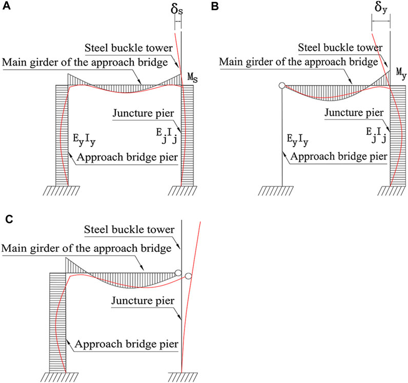
FIGURE 4. Deflection modes under self-weight: (A) double-fixed, (B) right-fixed, and (C) left-fixed.
It is evident that
In the case of the left-fixed connection, the negative bending moment at the fixed connection between the approach bridge pier and the main girder of the approach bridge caused the approach bridge pier to bend toward the midspan, pushing the buckle tower to bend toward the midspan and resulting in a tower deviation of 2.352 mm. The bending moment and deformation are shown in Figure 4:
The mechanical principle analysis is a general trend. Notwithstanding, according to the tower deviation data, the impact of the left-fixed connection on tower deviations under self-weight is weaker compared with the right-fixed connection.
When the structure is subjected to a horizontal cable force difference, refer to Supplementary Appendix Table A2 and Supplementary Appendix Figure A1.
Note: a) The tower deviation change refers to the absolute value of the difference between the tower deviation without approach bridge piers and other cases. b) The percentage refers to the absolute value of the ratio of the tower deviation change to the tower deviation without approach bridge piers.
Through an examination of the mechanical principles underlying the data in Supplementary Appendix Table A2 and Supplementary Appendix Figure A2, conclusions can be drawn regarding the impact of the horizontal cable force difference at the midspan.
The tower deviation with the double-hinged connection mode decreased by 0.239 mm compared to the case of no approach bridge piers, indicating a weak regulation effect on tower deviations.
The tower deviation with the right-fixed connection mode decreased by 18.407 mm compared to the case of no approach bridge piers, a reduction of 23.781%, indicating a sound regulation effect. This demonstrates that apart from the deflection effect induced by the self-weight in the right-fixed connection, there are other factors that significantly influence tower deviations. The schematic comparison of deflection between the right-fixed connection and the double-hinged connection is plotted in Figure 5.
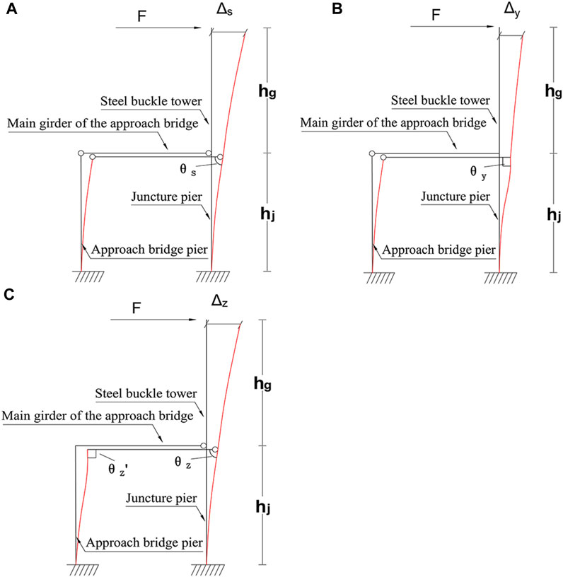
FIGURE 5. Different deflection modes under horizontal cable force toward the midspan: (A) double-hinged, (B) right-fixed, and (C) left-fixed.
When the structure is subjected to the horizontal cable force difference toward the midspan,
The double-hinged connection relies entirely on the approach bridge pier to improve the thrust stiffness, while the right-fixed connection, in addition to the impact of the thrust stiffness of the approach bridge pier itself, also reduces tower deviations by virtue of the geometric relationship between the piers and girders. Therefore, the right-fixed connection has a significant advantage over the double-hinged connection in terms of tower deviation control.
The tower deviation with the left-fixed connection mode decreased by 0.964 mm compared to the case of no approach bridge piers, a reduction of 1.245%, indicating slightly stronger control than the double-hinged connection. Compared to the double-hinged connection, the left-fixed connection reduces tower deviations not only by relying on the thrust stiffness of the approach bridge pier but also by virtue of the geometric relationship between the piers and girders. The schematic comparison of deflection between the double-hinged connection and the left-fixed connection is provided in Figure 5.
When the structure is subjected to the horizontal cable force difference toward the midspan, with the longitudinal girder stiffness being large enough, the elongation of the longitudinal girder is a higher-order trace, and the approach bridge pier is approximately parallel to the juncture pier. Since
Compared with the right-fixed connection, since the flexibility of the approach bridge pier is much larger than that of the main girder of the approach bridge, the left-fixed connection has a weaker effect on restricting the composite buckle tower from rotating toward the midspan relative to the main girder, and its effect on controlling tower deviations is also relatively diminished.
The tower deviation with the double-fixed connection mode decreased by 19.18 mm compared to the case of no approach bridge piers, a reduction of 24.781%. The double-fixed connection can be regarded as a combination of left-fixed and right-fixed connections, so its control effect is slightly stronger than the right-fixed connection alone. However, the disparity in the control effects between the two is merely 1%, rendering it statistically insignificant.
The tower deviation data under the influence of the horizontal cable force difference away from the midspan is the opposite number of the tower deviation data under the influence of the horizontal cable force difference toward the midspan. Therefore, without considering the self-weight, the approach bridge–composite buckle tower structure has in-plane isotropic mechanical properties.
So far, we have separately studied the tower deviation and mechanical principles of different pier–girder connection modes under self-weight load and horizontal cable force differences. The former reveals that the right-fixed connection has the greatest impact on tower deviations under self-weight, while the latter unveils that the right-fixed connection has the best regulation effect on tower deviations under horizontal cable force differences.
Since the tower deviation caused by these two loads in the right-fixed connection is in opposite directions, the right-fixed pier–girder connection can effectively control the tower deviation induced by the horizontal cable force difference toward the midspan. The control effect mainly stems from the “T”-type rigid frame formed by the main girder of the approach bridge and the composite buckle tower. The deflection effect caused by the self-weight of the main girder of the approach bridge makes the composite buckle tower bend away from the midspan and also restricts the composite buckle tower from rotating toward the midspan relative to the main girder. However, this approach necessitates the prior consolidation of the steel buckle tower and junction pier before the installation of the main girder of the approach bridge.
Based on the source of the impact of the approach bridge on tower deviations, it can be deduced that the first span of the approach bridge has the greatest impact on tower deviations. Therefore, only the first span of the approach bridge is considered. The effects of the approach bridge pier height and component flexural stiffness on the thrust stiffness of the approach bridge–composite buckle tower structure can be discussed after the theoretical formula. By combining computer programs with analytical formulas, a sensitivity analysis of the impact of component properties on the thrust stiffness can be conducted.
According to Section 2, the optimal method for connecting the approach bridge to the composite buckle tower is consolidating the juncture pier and the main girder of the approach bridge while hinging the approach bridge pier with the main girder. The mechanical model is shown in Figure 6, with the basic assumptions as follows:
(1) The influence of the longitudinal slope and temperature changes is ignored.
(2) The self-weight of vertical components is ignored.
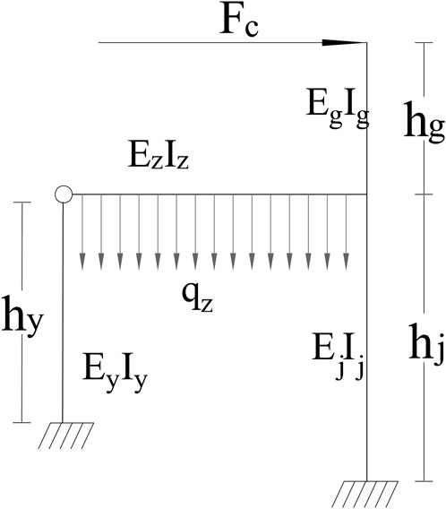
FIGURE 6. Mechanical model.
In Figure 6,
Figure 6 reveals that the structure is a second hyper-static structure. Assuming that the bearing compression between the piers and girders is the positive direction of the vertical basic unknown force, the structure is simplified, and the basic system is shown in Figure 7.
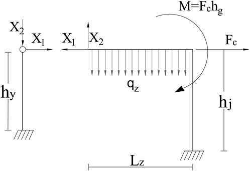
FIGURE 7. Basic system.
The basic equation of the force method is obtained from the displacement coordination conditions:
The expression of the basic unknown quantity is obtained by the elimination method:
The displacement coefficients and free terms are obtained from the principle of virtual work and the multiplication method:
First, the parameters are substituted into Equations 3 and 4 to derive the coefficients and free terms, respectively, and then the coefficients and free terms are substituted into Eq. 2 to obtain the basic unknown quantities
The tower deviation of the completely rigid connection is obtained using the graph multiplication method:
According to Section 2, one of the effects of the right fixed pier–girder connection mode in controlling tower deviations is to restrict the rotation of the composite buckle tower relative to the main girder of the approach bridge. However, it is important to note that the materials and boundary conditions used in the finite-element design represent idealized states, which may differ from the actual situation. As illustrated in Figure 8, when the rigid connection is subjected to the deflection effect caused by the self-weight of the main girder of the approach bridge, one side of the rigid device is compressed and the other side is tensioned, causing a relative rotation angle between the piers and girders. Therefore, it is necessary to consider the local force situation at the pier–girder connection and add a correction term for the partially rigid pier–girder connection in the theoretical calculation.
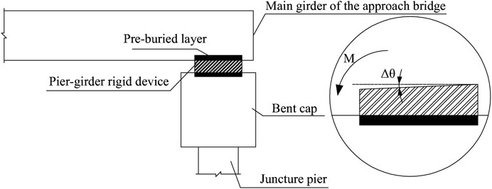
FIGURE 8. Schematic diagram of the deformation of the rigid connection details.
From an overall perspective, the basic unknown force has been obtained in the last section, i.e., the known force of the approach bridge pier on the main girder of the approach bridge. From a local perspective, the steel buckle tower is fixed on the top of the juncture pier, and the main girder of the approach bridge is fixed with the juncture pier through the anchoring device. Therefore, the deflection effects of the main girder of the approach bridge on the anchoring device and the steel buckle tower on the juncture pier are demonstrated in Figure 9.
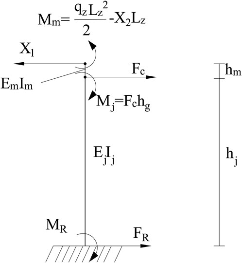
FIGURE 9. Schematic diagram of the local stress on the pier–girder connection.
Figure 9 shows that
The bearing reaction force is simplified to the top surface of the juncture pier, as presented in Figure 10.
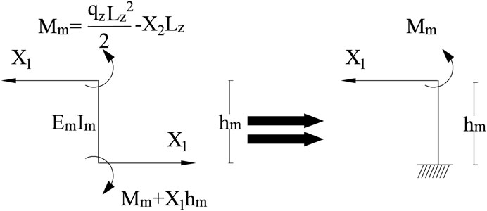
FIGURE 10. Mechanical model of the anchoring device.
Based on the simplified calculation method of cantilever beam rotation angles, the relative rotation angle between the juncture pier and the main girder of the approach bridge is as follows:
From the completely rigid tower deviation
The thrust stiffness of the partially rigid pier–girder connection is as follows:
The determination of displacement coefficients and free terms serves as the foundation for calculating the thrust stiffness. By observing the free term, it is found that there are two types of load terms in the formula. If
We apply the self-weight load to the approach bridge–composite buckle tower structure and sequentially apply a 0.4 to 1 times horizontal cable force difference, as plotted in Supplementary Appendix Figure A3.
It can be seen that when the approach bridge–composite buckle tower structure bears self-weight, the tower deviation is linearly related to the horizontal cable force difference. The thrust stiffness solution at this time is as follows:
A 0.4 to 1 times horizontal cable force difference toward the midspan is applied to the approach bridge–composite buckle tower structure, as shown in Supplementary Appendix Figure A4.
The thrust stiffness solution is
Therefore, within the range of small deformation, the thrust stiffness of the completely rigid pier–girder connection of the approach bridge–composite buckle tower structure is only related to the bending stiffness EI and height h. The effect of self-weight is to move the “horizontal cable force difference–tower deviation” line down as a whole. Meanwhile, according to the mechanics of materials, the size of the relative rotation angle between the piers and girders is related to the external load, so the effect of the self-weight of the main girder of the approach bridge is to provide pre-deviation and an initial relative rotation angle.
The thrust stiffness of the completely rigid pier–girder connection remains unaffected by external loads and self-weight. Therefore, we can exclude the self-weight load term, and the horizontal cable force difference can be treated as the horizontal unit load, at which point the free term is as follows:
The basic unknown forces solved at this time are denoted as
The thrust stiffness of the completely rigid connection is as follows:
The size of the relative rotation angle is related to the external load, so the relative rotation angle comprises two parts: one part is the initial relative rotation angle caused by
Within the range of small deformation, the tower deviation caused by the initial relative rotation angle also moves the “horizontal cable force difference–tower deviation” line up and down as a whole and does not affect the slope, so the relative rotation angle caused by the self-weight of the main girder of the approach bridge has no impact on the overall thrust stiffness of the structure, at which point the free term is as follows:
The basic unknown forces at this time are denoted as
The thrust stiffness of the partially rigid pier–girder connection is as follows:
According to Eq. 15, the thrust stiffness considering local deformation at the rigid connection of the pier and girder is not unique.
Although the self-weight of the main girder of the approach bridge does not affect the calculation of the thrust stiffness, it has a great impact on tower deviations, so it needs to be solved. The free term at this time is as follows:
The basic unknown forces are represented as
The initial relative rotation angle is as follows:
The total pre-deviation is as follows:
There are various formulas for the theoretical calculation method of thrust stiffness, and manual calculation is cumbersome and prone to errors, so it is calculated with the help of programs. MATLAB, VB, Python, and other calculation programs can be combined with the theoretical calculation method. The detailed process is as follows:
The heights of the approach bridge pier, juncture pier, and steel buckle tower, and the span length of the main girder of the approach bridge are as follows:
Using the deflection formula of the cantilever girder and finite-element software, the corresponding flexural stiffness values are obtained as follows:
After a series of calculations, the tower deviation of the completely rigid pier–girder connection under the action of the unit tower top horizontal cable force difference is obtained as follows:
The thrust stiffness of the completely rigid connection is obtained as follows:
The detailed calculation process of the thrust stiffness by computer programs is illustrated in Figure 11.

FIGURE 11. Flow chart of calculating the thrust stiffness using programs.
The thrust stiffness value calculated entirely by Midas/Civil is 6,780 kN/m, which differs from the value calculated by the analytic formula by 11 kN/m, with a deviation percentage of 0.16%, which is satisfactorily consistent.
When the calculation program is used to solve the thrust stiffness, the formula needs to be input only for the first time; the subsequent calculations only need to input the data of step 1 to derive the value of thrust stiffness, achieving a rapid calculation of the thrust stiffness of the approach bridge–composite buckle tower structure. Therefore, the analytic formula can be used to validate the model’s accuracy and perform sensitivity analysis, providing guidance for the design of structural member dimensions, sections, and materials. The other formulas share the same purpose.
Section 5.5 used a computer program to achieve a rapid calculation of the theoretical formula of thrust stiffness, and this section will further study the influence rule of changing component properties on the overall thrust stiffness of the structure.
There are a total of eight component property indexes:
By comparing Supplementary Appendix Figure A5 with each set of data, taking the first value as a reference to solve the change percentage, the findings can be listed as follows:
(1) The impact of changing the approach bridge pier height
(2) For every 2.439% increase in the juncture pier height
(3) For every 9.091% increase in the steel buckle tower height
Analyzing Supplementary Appendix Figure A6 and similarly calculating the percentage changes, we can find the following:
(1) For every 3.223% increase in the flexural stiffness of the approach bridge pier
(2) For every 6.250% increase in the flexural stiffness of the juncture pier
In conclusion, the height and flexural stiffness of the approach bridge pier have minimal impacts on the overall thrust stiffness of the structure; hence, the design of the approach bridge pier height and sectional size can be tailored to match the specific on-site conditions. The higher the steel buckle tower, the less advantageous it is for the overall thrust stiffness of the structure. Enhancements in the span length and flexural stiffness of the main girder of the approach bridge, as well as increases in the height and flexural stiffness of the juncture pier, collectively contribute to the improved overall thrust stiffness of the structure.
A particular deck-type steel pipe concrete arch bridge has a calculated span length of 475.0 m and a rise-to-span ratio of 1/5.278, and the arch axis is a catenary line with an arch axis coefficient of m = 2.2. The main arch rib adopts a constant-width and variable-height space truss structure. The radial height of the main chord tube at the arch crown is 7.0 m, and the radial height of the main chord tube at the arch foot is 10.0 m, with the radial height of the arch section varying according to a quadratic parabola. Each single arch rib is composed of two steel pipe concrete chord tubes each at the top and bottom, with an external diameter of 1,400 mm. The transverse center distance of the chord tubes is 2.5 m, and the center distance between the two arch ribs in the transverse bridge direction is uniformly 16.0 m. Lateral braces are set up inside the ribs, and wind braces, flat braces, and “X” braces are set up between the ribs. The main arch rib is divided into 15 sections from the arch foot to the arch crown, plus the joint segment at the arch crown, and there are a total of 62 segments in the entire bridge. The Midas/Civil finite-element analysis model was established, consisting of a total of 3,654 beam elements and 240 tension-only elements, as presented in Figure 12.
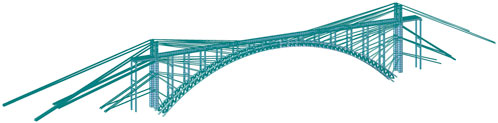
FIGURE 12. Cantilever assembly model for arch ribs using Midas/Civil.
The basic assumptions are as follows:
(1) When the buckle tower is displaced, the buckle cable length remains unchanged.
(2) The arch rib is a rigid body that does not undergo elastic deformation but only rigid displacement.
(3) The change in the buckle tower height is a higher-order trace compared to tower deviations.
Figure 13 shows the calculation diagram, where the red dashed lines indicate the positions of the buckle cable, buckle tower, and arch segment after displacement.
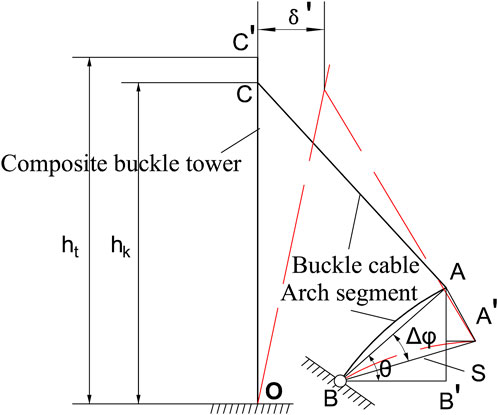
FIGURE 13. Schematic diagram of the influence of tower deflections on the line shape of the arch rib.
According to the principle of small deformation and basic assumptions, we can obtain
where
According to Eq. 24 and the complementary angle theorem of right angles, we know that
where
Knowing the relationship between the displacement of the buckle point C and the line shape of the arch rib, while the study of the thrust stiffness is the displacement at the top of the structure, to determine the relationship between the longitudinal thrust stiffness of the buckle tower and the line shape of the arch rib, the deviation of the tower top C′ needs to be distributed to the buckle point C first.
By using the triangular distribution method, we obtain
where
According to the thrust stiffness theory,
As demonstrated in Figure 14, the various stages where the buckle point will change are explored. There are a total of five buckle points on the composite buckle tower, K1–K5. The last arch segments lifted by them are #2, #5, #9, #12, and #15. The remaining buckle cables are equivalent to increasing the stiffness of the arch segments, so the elastic deformation of the middle part of the arch segment is not considered. The change in distance between the arch foot point O and the buckle points K1′–K5' is ignored, focusing only on their elevation changes. At the same time, we maintain the initial tension of the buckle cables, taking into account the influence of the approach bridges, at the same level as the initial tension of the buckle cables in the standard tangent assembly. This approach aims to minimize elevation deviations resulting from the elongation of the buckle cables.
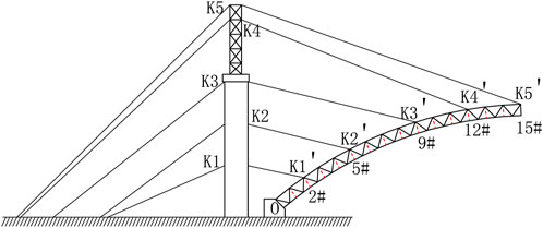
FIGURE 14. Schematic diagram of the distribution of buckle points on the composite buckle tower and arch rib.
During the installation stage of the juncture pier and steel buckle tower, an approach bridge is incorporated, forming a right fixed joint effect of approach bridges, as plotted in Figure 3.
By comparing it with the elevation changes during the normal tangent assembly of the arch rib, the difference is obtained, as provided in Supplementary Appendix Figure A7.
As can be seen from Supplementary Appendix Figure A7, it is evident that the influence of the joint effect of approach bridges on the elevation of the arch rib becomes more pronounced with increasing distance, which is consistent with the rules described in Equations 25 and 26. The node coordinates of Midas/Civil were extracted, and geometric calculations were performed to obtain the related parameters, as tabulated in Supplementary Appendix Table A3.
Note:
(1) According to Eq. 21, the EI of the steel buckle tower and the juncture pier is different by an order of magnitude. At this time, using the triangular distribution method results in a relatively large error in tower deviations, so we calculate separately for #2, #5, and #9 and #12 and #15 according to the distribution of buckle points.
(2) What is extracted is the deviation at the top of the juncture pier and steel buckle tower under the self-weight load of the approach bridge–composite buckle tower structure.
After calculation, the theoretical elevation change deviation value caused by pre-deviation is obtained. It is compared with the elevation change deviation value obtained from the model, as listed in Supplementary Appendix Table A4:
Note: The second-order deviation is the difference between the elevation change deviation values calculated by the model and the theory.
Supplementary Appendix Table A4 reveals that there is a second-order deviation between the elevation change deviation values obtained by theoretical calculation and model calculation, and the second-order deviation of the later stage is greater. According to the research in Section 2, the influence of the right fixed pier–girder connection mode on tower deviations stems from two aspects: 1) the deflection effect caused by the self-weight of the main girder of approach bridges makes the composite buckle tower deflect away from the midspan; and 2) it restricts the rotation of the composite buckle tower relative to the main girder of approach bridges toward the midspan.
Therefore, the second-order deviation is caused by the effect of constrained rotation, and it can be found that the higher the buckle point elevation and the later the construction stage, the greater the impact of constrained rotation on the tower deviation and arch rib elevation.
Utilizing the relationship between thrust stiffness and arch rib elevation changes, we have extracted the relevant calculation parameters from the preceding text, as displayed in Supplementary Appendix Table A5.
Upon substituting relevant parameters into Eq. 27, the effects of pre-deviation and constrained rotation on the cable force in the joint effect of approach bridges can be observed in Supplementary Appendix Figure A8. The influences of pre-deviation and constrained rotation on the cable force tend to become more significant in the later stages. During these stages, with greater
Therefore, the joint effect of approach bridges can function as a remedial measure. When the actual construction line of the arch ribs in the middle and later stages deviates significantly downward from the design line, the cable force that is needed to install new arch segments becomes overly large. In such cases, the joint effect of approach bridges can be utilized to generate pre-deviation in the buckle tower and to constrain pier–girder rotation, effectively substituting for a portion of the cable force. This also reduces the potential elevation errors that may arise in subsequent arch ribs compared with the case without approach bridges. Moreover, the function of constrained rotation serves as a manifestation of enhanced thrust stiffness in buckle towers. Therefore, through the application of the thrust stiffness analytical formula for sensitivity analysis, it becomes possible to guide the design of structural member properties, ultimately identifying the most cost-effective approach to enhance thrust stiffness.
In summary, this study, centered around the engineering scenario of a large-span, deck-type, steel pipe concrete arch bridge assembled through a cantilever suspension with stay cables, investigates the calculation method and the impact on the buckle tower stiffness, considering the joint effect of approach bridges. The primary conclusions are as follows:
(1) The main girder of the approach bridge and the composite buckle tower are firmly interconnected, creating a robust “T”-type rigid structure. In this configuration, the junction of the pier and girder imposes constraints on the rotation of the composite buckle tower. When subjected to self-weight, the deflection of the main girder causes the composite buckle tower to deflect away from the midspan.
(2) The weight of the approach bridge’s main girder imparts a pre-deviation to the buckle tower, resulting in axial compression between the pier and the girder. This, however, does not impact the thrust resistance stiffness of the tower–girder structure.
(3) The height and flexural stiffness of the approach bridge pier have minimal influence on the overall thrust resistance of the structure. Additionally, a greater height for the steel buckle tower is detrimental to the overall thrust resistance of the structure. However, increasing the length and bending stiffness of the main girder of the approach bridge, as well as raising the height and enhancing the bending stiffness of the junction pier, can effectively enhance the overall thrust resistance of the structure.
(4) In situations where a significant downward elevation error occurs in the middle and later stages of arch rib construction, the tension in the back cables can become excessively high for the installation of a new arch segment. In such cases, the joint effect of the approach bridge can be used to decrease the tension in the back cables, resulting in a smaller elevation error in the subsequent arch ribs when compared to the joint effect without an approach bridge.
(1) The derivation of the thrust stiffness analytical formula does not consider the impact of the longitudinal slope and temperature changes of the main girder; thus, the analytical formula needs further refinement.
(2) The buckle-anchored stay cables and the composite buckle tower form a multiple-time hyper-static structure. However, this paper calculates the equivalent horizontal cable force difference at the tower top, i.e., the horizontal cable force difference ratio relative to the actual position distribution and size, which can generate horizontal loads on the tower top equal to the tower deviation. Therefore, further research is needed to facilitate the intelligent calculation of the impact on each cable.
The original contributions presented in the study are included in the article/Supplementary Material; further inquiries can be directed to the corresponding author.
SW: writing–original draft and writing–review and editing. JF: writing–original draft. LY: writing–review and editing. GC: writing–review and editing. DJ: writing–review and editing.
The author(s) declare that financial support was received for the research, authorship, and/or publication of this article. This work was supported by the National Natural Science Foundation of China (nos 51608080 and 52108267), the Science and Technology Innovation Project for the Construction of the Chengdu Chongqing Double City Economic Circle (KJCXZD2020032), the Natural Science Foundation of Chongqing (cstc2021jcyj-msxm2491), the Chongqing Science and Technology Innovation and Application Development Special Key Project (CSTB2022TIAD-KPX0205), and the Guangxi Key R&D Plan Project (AB22036007-8), which are all gratefully acknowledged.
The authors declare that the research was conducted in the absence of any commercial or financial relationships that could be construed as a potential conflict of interest.
All claims expressed in this article are solely those of the authors and do not necessarily represent those of their affiliated organizations, or those of the publisher, the editors, and the reviewers. Any product that may be evaluated in this article, or claim that may be made by its manufacturer, is not guaranteed or endorsed by the publisher.
The Supplementary Material for this article can be found online at: https://www.frontiersin.org/articles/10.3389/fmats.2023.1321177/full#supplementary-material
Chen, B. W., Han, L. H., Qin, D. Y., and Li, W. (2023). Life-cycle based structural performance of long-span CFST hybrid arch bridge: a study on arch of Pingnan Third Bridge. J. Constr. Steel Res. 207 (1), 107939. doi:10.1016/J.JCSR.2023.107939
Chen, H. D., Wu, X. G., Yao, S. S., and Li, Z. (2017). Longitudinal anti-push rigidity of the non side tower for multi-tower cable-stayed bridge based on the principle of deformation coordination. J. Beijing Jiaot. Univ. 41 (4), 40–46. doi:10.11860/j.issn.1673-0291.2017.04.00
Deng, H. C., Lu, W., Li, Q. P., Zhou, Y. K., Tao, L., and Qiang, Y. L. (2020). Research on accurate calculation method of cable tower deviation in cable hoisting system. Highway 65 (8), 226–232.
Deng, J. M. (2009). Geom etrical analysis of arch rib elevation change caused by tower deviation during cable hoisting construction. J. Chongqing Jiaot. Univ. Nat. Sci. Ed. 28 (3), 505–507. doi:10.3969/j.issn.1674-0696.2009.03.08
Ding, W., Kang, H. J., Zhang, X. Y., Su, X. Y., and Cong, Y. Y. (2023). Dynamic modeling and analysis on planar free vibration of long-span arch bridges during construction. Appl. Math. Model. 121 (1), 843–864. doi:10.1016/J.APM.2023.05.028
Gu, Y., Li, Y. D., and Liu, S. Z. (2015). Research on construction control of long-span CFST arch bridge. Appl. Mech. Mater. 4075 (777), 88–93. doi:10.4028/www.scientific.net/AMM.777.88
Hao, N. B., and Gu, A. B. (2015). Construction control of 500 m scale concrete-filled steel tubular arch bridge. J. Southwest Jiaot. Univ. 50 (4), 635–640. doi:10.3969/j.issn.0258-2724.2015.04.010
Hao, N. B., and Gu, A. B. (2016). Alignment adjustment method of concrete filled steel tubular arch bridge in arch rib hoisting. J. Chongqing Jiaot. Univ. 35 (3), 1–5. doi:10.3969/j.issn.1674-0696.2016.03.01
Hao, N. B., and Gu, A. B. (2018). Error control method for super-long span concrete filled steel tubular arch bridge. Sci. Technol. Eng. 18 (15), 149–154. doi:10.3969/j.issn.1671-1815.2018.15.022
JTG/T 3650 (2020). Technical specifications for construction of highway bridges and culverts. Beijing: People's Communications Publishing House.
Li, Y., Wang, J. L., and Ge, S. S. (2017). Optimum calculation method for cable force of concrete-filled steel tube arch bridge in inclined cable-stayed construction. J. Highw. Transp. Res. Dev. Engl. Ed. 11 (1), 42–48. doi:10.1061/JHTRCQ.0000549
Liu, X. C. (2008). Construction process monitoring of cable suspension for large span box arch bridge. Chengdu: Master's thesis of Southwest Jiaotong University.
Liu, Z. G., Zhou, S. X., Zou, K. R., and Qu, Y. H. (2022). A numerical analysis of buckle cable force of concrete arch bridge based on stress balance method. Sci. Rep. 12 (1), 12451. doi:10.1038/S41598-022-15755-W
Long, X. H. (2012). Analysis of mechanical performance on cable tower and buckle tower system of A big span steel box arched bridge during construction. Hunan: Master's Degree Thesis of Central South University.
Mo, Z. Q. (2021). Research on the influence of main cable slippage and tower deflection in the design of cable hoisting system. Highway 66 (3), 163–168.
Qin, S. Q. (2003). Control method of stress-free status for erection of cable-stayed bridges. Bridge Constr. 33 (2), 31–34. doi:10.3969/j.issn.1003-4722.2003.02.009
Qin, S. Q. (2008). Application of unstressed state control method to calculation for erection of cable-stayed bridge. Bridge Constr. 38 (2), 13–16.
Wang, H. P. (2013). Research on application of unstressed state method in the construction control of long-span cfst arch bridge. Chengdu, China: Master's Degree Thesis of Southwest Jiaotong University.
Xu, Y., Shen, C. Y., Zhu, Y. B., and Wang, C. S. (2016a). Improved iteration algorithm for determination of tension of fastening stays for cantilever construction of arch bridge. Bridge Constr. 46 (2), 65–69. doi:10.3969/j.issn.1002-0268.2016.06.010
Xu, Y., Zhan, B. L., Li, Y., and Shen, C. Y. (2016b). An optimum calculation method of cable force of CFST arch bridge in inclined cable hoisting construction. J. Highw. Transp. Res. Dev. 33 (6), 61–67. doi:10.3969/j.issn.1002-0268.2016.06.010
Xu, Z. Q. (2011). Technology research on timely adjustment of installation linear error about arch rib of large span arch bridge. Chongqing: Master's Degree Thesis of Chongqing Jiaotong University.
Zhang, J. M. (2001). Bearing capacity and construction control research of long-span concrete filled steel tubular arch bridges. Guangdong: Doctoral Dissertation of South China University of Technology.
Zhang, Z. C., Ye, G. R., and Wang, Y. F. (2004). Optimization of cable tension in adjustment of arch rib alignment of long-span cantilever bridge. Appl. Mech. 21 (6), 187–192.
Zheng, J. L., Xu, F. Y., and Tang, B. S. (1996). Simulation and calculation method for construction of steel arch trusses erected by jacked diagonal pulling and buckling suspension of yongning yongjiang bridge in Guangxi. Bridge and structural engineering society of China highway society 1996 bridge academic proceedings. Beijing: People's Transportation Press. 214–228.
Zhou, S. X. (2002). Rib assemble and construction control calculation of Zhejiang Sanmen Jiantiao bridge. J. Chongqing Jiaot. Inst. 11 (6), 1–5. doi:10.3969/j.issn.1674-0696.2002.02.001
Zhou, S. X., Jiang, L. Z., Zeng, Z., and Zhou, J. T. (2000a). Simulation and calculation of cable suspension force of diagonal buckling for segmental construction of arch bridges. J. Chongqing Inst. Transp. 19 (3), 8–12. doi:10.3969/j.issn.1674-0696.2000.03.003
Keywords: bridge engineering, tower deviation control, stay button hanging, pushing stiffness, joint effect
Citation: Wang S, Feng J, Yang L, Cai G and Jiang D (2024) Harnessing the joint effect of approach bridges in arch bridge construction: an analytical study on thrust stiffness and elevation error mitigation. Front. Mater. 10:1321177. doi: 10.3389/fmats.2023.1321177
Received: 13 October 2023; Accepted: 29 December 2023;
Published: 06 February 2024.
Edited by:
Anbang Li, Xi’an University of Architecture and Technology, ChinaReviewed by:
Xiaoqiang Yang, Fuzhou University, ChinaCopyright © 2024 Wang, Feng, Yang, Cai and Jiang. This is an open-access article distributed under the terms of the Creative Commons Attribution License (CC BY). The use, distribution or reproduction in other forums is permitted, provided the original author(s) and the copyright owner(s) are credited and that the original publication in this journal is cited, in accordance with accepted academic practice. No use, distribution or reproduction is permitted which does not comply with these terms.
*Correspondence: Ligui Yang, eWFuZ2xpZ3VpQGNxanR1LmVkdS5jbg==
Disclaimer: All claims expressed in this article are solely those of the authors and do not necessarily represent those of their affiliated organizations, or those of the publisher, the editors and the reviewers. Any product that may be evaluated in this article or claim that may be made by its manufacturer is not guaranteed or endorsed by the publisher.
Research integrity at Frontiers
Learn more about the work of our research integrity team to safeguard the quality of each article we publish.