 Yugang Wang1
 Zhantao Li
- 1Shandong Swan Cotton Industrial Machinery Stock Co., Ltd., Jinan, China
- 2Xinjiang Swan Modernization Agricultural Machinery Equipment Co., Ltd., Wujiaqu, China
- 3College of Mechanical and Electrical Engineering, Shihezi University, Shihezi, China
Introduction: The wear failure of spindle will lead to a decrease in cotton harvesting rate of the cotton picker during field operation and serious wastage.
Method: Three types of spindle samples at different installation positions and working areas were obtained through field experiments to explore the wear failure law of spindle hook teeth of cotton picker during field operation. Hardness of hook tooth coating and substrate of spindles were tested, surface and cross-section microstructure of the spindle hook teeth were characterized, and wear area and width of the spindle hook teeth were extracted.
Results: Results showed that the hardness of the hook tooth coating is evidently higher than that of the substrate; the average coating hardness of the No. 3 spindle hook teeth reaches the maximum at 1033.6 HV0.1; defects, such as microcracks and micropores, exist in the coating of the three types of spindle hook teeth; and the thickness of the coating is between 70 and 130 μm. The wear area of spindle hook tooth changes exponentially and the wear width changes linearly with the increase of field operation area at the same installation position. The wear area and width of the spindle hook teeth gradually increase with the decrease of the installation height and the wear change of the hook teeth is negatively correlated with the installation height in the same field operation area.
Discussion: The wear failure of spindle hook tooth is mainly caused by abrasive, fatigue, and oxidation wear. The results of this study can provide a reference for improving the wear resistance of spindle hook teeth.
1 Introduction
Cotton is the second largest crop after food and an important strategic material for the country’s livelihood (Wang et al., 2021; Li et al., 2022a). The cotton picker is a large type of equipment for mechanized harvesting of cotton and commonly used in the cotton harvesting process. The spindle is a key core component of the cotton picker, and its performance directly determines the picking efficiency and effect of the cotton picker field operation (Chen et al., 2020b; Bi, 2007; Li et al., 2022b). At the same time, the spindle is also the most consumed among wear parts on the cotton picker, and spindle hook teeth are very prone to wear failure problems (Wu et al., 2013; Zhang et al., 2017; Li et al., 2018; Gu et al., 2021; Li et al., 2022a). The wear failure of spindle will lead to a decrease in cotton harvesting rate of the cotton picker during field operation and serious wastage.
Improving the wear resistance and prolonging the service life of the spindle in the field are important. At present, the method of electroplating chromium coating is often used to strengthen the spindle, the failure of chromium coating has been extensively investigated (Pina et al., 1997; Wang et al., 2007; Weiss et al., 2015; Lunarska et al., 2001; Zhang et al., 2012; Zhang et al., 2021; Zhang et al., 2018) randomly obtained the spindle samples from the picking head, characterized the wear failure change and morphology of the spindle hook teeth, analyzed the wear change process and failure form of the spindle hook teeth, and applied electromagnetic treatment to different brands of spindles to reduce the residual stress of the matrix and improve wear resistance. Amanov (Amanov et al., 2019) proposed an ultrasonic nanocrystal surface modification technology that uses ultrasonic energy to induce severe plastic deformation, improve the surface integrity of the material, increase the mechanical properties of the spindle surface, and improve wear resistance. Meng (Meng et al., 2016a; Meng et al., 2016b) investigated the friction performance modification of the spindle sleeve and the sleeve and applied nickel coating on the surface of the spindle via chemical method. Sun (Sun et al., 2021) used plasma spraying technology to treat the surface of cotton picker spindles to improve surface hardness and wear resistance. Luo(Luo et al., 2018) characterized the micro-morphology of the spindle hook teeth in different operation periods using scanning electron microscopy, established the friction mechanics model of the de-cotton process, and indicated that the wear failure of the spindle hook teeth is mainly caused by abrasive wear. Gu (Gu et al., 2021; Gu et al., 2022) extracted the area and the width of wear region and used them as evaluation indexes, the results revealed that the wear area of spindle hook teeth increases exponentially and the wear width increases linearly with the increase of the working area. The above research results have certain reference value for exploring the wear failure mechanism of the spindle hook teeth. And, the wear failure of the spindle hook teeth is mainly caused by the wear between the spindle hook teeth and the cotton. Research on the wear change of the spindle has mainly focused on the main picking parts of cotton, and studies on the wear failure of the spindle at the height of the seat tube needs further refinement. Practical field production demonstrated that some differences exist in the wear failure changes of spindle hook teeth at various installation positions on the spindle seat tube.
Causes of the wear failure of spindle hook teeth were analyzed to explore the wear failure changes during the field operation of spindle picking comprehensively. According to the spatial distribution law of cotton bolls in Xinjiang, three different height positions (upper, middle, and lower) on the spindle pipe were determined and spindle samples of field operation were obtained at these positions. Combined with structural parameters of the spindle, the sample preparation method of the spindle sample was developed. The surface and cross-section microstructure of the hook tooth coating, wear failure change of the hook tooth and wear failure morphology, and the cause of wear failure of the hook tooth were analyzed by characterizing the microhardness of the hook tooth coating and the substrate. The research results can provide a reference for further improving the wear failure mechanism and resistance of spindle hook teeth.
2 Materials and methods
2.1 Test materials
The test samples are three types of spindles currently used in Xinjiang market, namely, No. 1, 2, and 3. The overall structure of spindles is shown in Figure 1.
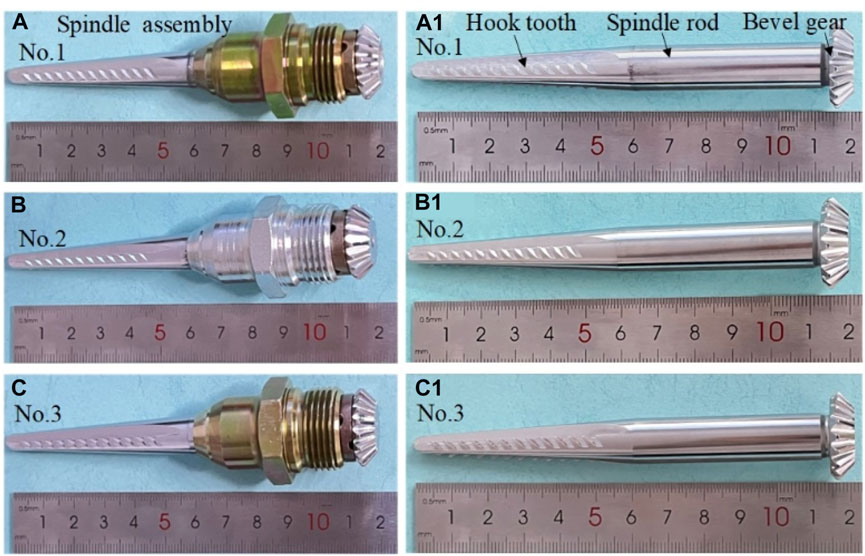
FIGURE 1. Test spindle sample: (A–C) spindle assembly and (a1–c1) spindle.
2.2 Test equipment
Cotton picker (Model: CP690, equipped with Pro-16 picking head), scanning electron microscope (Model: S-4800), electric spark wire cutting machine (Model: DK-7735), microhardness tester (Model: Duramin-40), energy spectrum analyzer (Model: XFlash5030), sample mosaic machine (Model: XQ-1), ultrasonic cleaner (Model: DL-720D), metallographic sample grinding and polishing machine (Model: ZMP-2000), special tools for spindle disassembly, sample bag, sandpaper, polishing agent, and marker pen.
2.3 Field test process
A field experiment was carried out from 25 September 2021 to 18 October 2021 during the cotton harvesting process in northern Xinjiang, China by installing spindle samples on the same cotton picker. Cotton bolls in Xinjiang are mainly distributed in 250–750 mm, with a concentration of more than 95% (Zhang, 2013). The test divided the spindle installation site into three different height ranges, namely, 150–250 (lowest installation position of the seat tube spindle height from the ground during field operation), 250–750, and 750–929 (highest installation position of the seat tube spindle height from the ground during field operation) mm, which correspond to the 1st–3rd, 3rd–15th, and 15th–20th spindle positions on the spindle seat tube range, respectively. The 2nd, 9th, and 16th positions within the corresponding position are selected as the installation position of the spindle, as shown in Figure 2. The three types of spindles were installed on No. 4, 5, and 6 picking heads of the cotton picker, and three repeated tests were performed under the same operating interval at the same position of the same spindle. The field operation process of the cotton picker was tracked and recorded, as shown in Figure 3. The three types of installed spindles were disassembled according to the experimental design when the field operation area of the cotton picker reached 133.33, 266.66, 400, and 533.33 ha. Three spindles were disassembled under the same installation position and the same working area. The sample bag was sealed and marked accordingly after antirust treatment. The field operation parameters of the cotton picker are listed in Table 1, and the field environmental conditions during the operation are presented in Table 2.
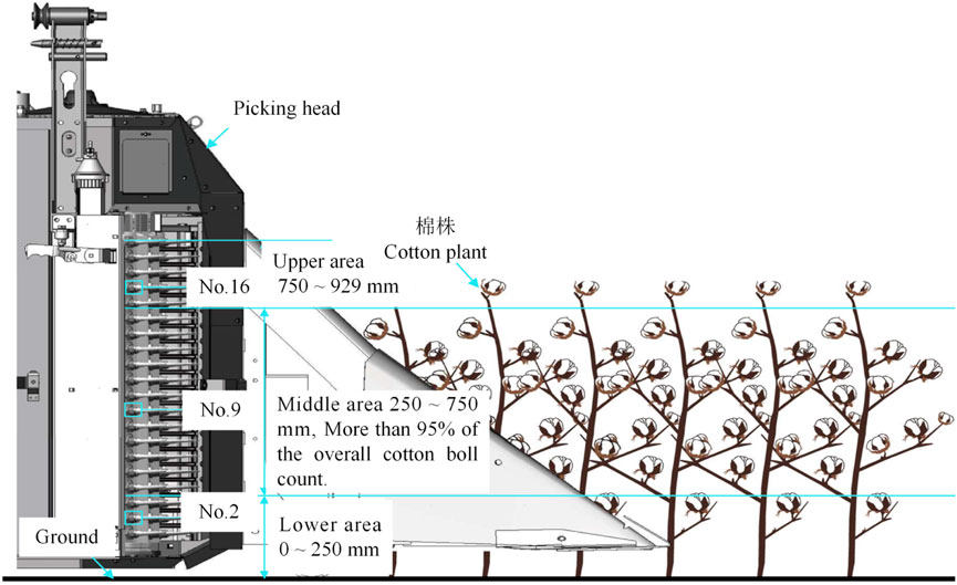
FIGURE 2. Diagram of the installation position of spindle.
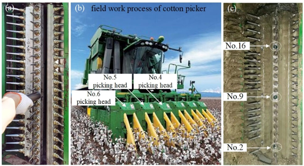
FIGURE 3. Field test process: (A) installation process of the spindle, (B) field work process of the cotton picker, and (C) disassembly process of the spindle.

TABLE 1. Working parameters of the cotton picker field operation.

TABLE 2. Field test environmental factors.
2.4 Preparation and characterization methods of test samples
The first hook tooth of the spindle was selected as the research object. The microstructure of the surface section of the hook tooth coating and the wear failure process of the hook tooth are explored and an electric wire cutting machine is used to cut the spindle sample to facilitate the characterization of the tooth surface structure of the spindle hook tooth. Figure 4A shows the cutting process of the surface sample of the spindle hook. The clamping position, cutting direction, and cutting path of the spindle are presented in Figure 4B. Figure 4C illustrates the observation sample of the tooth surface structure and the micro-morphology of the hook tooth surface of the spindle structure and hook tooth after wire cutting. The first hook tooth of the other row of hook teeth on the spindle was selected for wire cutting to characterize the cross-section microstructure of the hook tooth coating. The wire cutting process is depicted in Figure 4D. At this time, the clamping position, cutting direction, and cutting path of the spindle are shown in Figure 4E. The overall structure and sample of the spindle after cutting are presented in Figure 4F. The characterization samples of the cross section of the spindle hook tooth coating are obtained by inlaying, polishing, and preparing the samples under cutting.
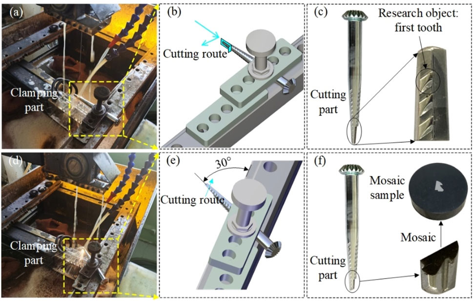
FIGURE 4. Sample preparation process: (A) surface sample cutting process, (B) clamping method of spindle, (C) surface sample, (D) section sample cutting process, (E) clamping method of spindle, and (F) section sample.
The samples were cleaned ultrasonically for 5 min and then dried with hot air. The hardness of the coating and substrate was tested with a microhardness tester. The test load was 100 g, and the holding time was 15 s. Each test was repeated three times, and the average value of these tests was taken as the hardness value of the coating and substrate. A scanning electron microscope was used to characterize the tooth surface structure of the spindle hook teeth, the microstructure of the surface section of the hook tooth coating, and the wear failure process of the hook teeth. The acceleration voltage was 15 kV, and the scanning time was 30 μs. A spectrometer was utilized to characterize the elemental composition and content of the wear surface of the spindle hook teeth. The acceleration voltage was 16 kV, the maximum scanning area was 1 mm2, and the maximum scanning distance was 11 mm.
3 Results and discussion
3.1 Coating and substrate hardness test of spindle hook tooth
Figure 5 shows the hardness test diagram of the hook tooth coating and the substrate of the three types of spindles. The average hardness of the hook tooth coating of No. 1, 2, and 3 spindles used in this test is 963.2 ± 36.25, 973.2 ± 20.57, and 1033.6 ± 13.91 HV0.1, respectively. The average hardness of No. 1, 2, and 3 spindle hook tooth matrixes is 438.3 ± 8.61, 463.7 ± 9.39, and 482.0 ± 7.92 HV0.1, respectively. Hence, the hardness of the hook tooth coating and the substrate of the No. 3 spindle sample is the maximum.
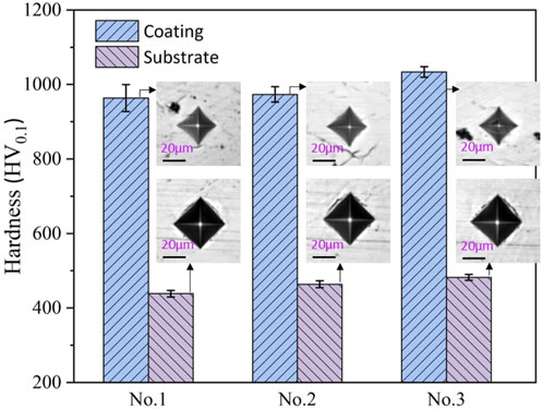
FIGURE 5. Hardness test of hook tooth coating and substrate.3.2. Figures, Tables and Schemes.
3.2 Characterization and analysis of surface and cross-section microstructure of spindle hook tooth coating
Figure 6 presents the tooth surface structure and the cross-section microstructure of the coating surface of the three types of spindle hook teeth. Figures 6A–C illustrate the tooth surface structure of No. 1, 2, and 3 spindle hook teeth, respectively. Among the three types of spindles used in the experiment, No. 2 spindle hook teeth are the sharpest and a certain passivation phenomenon occurs in No. 1 and 3 spindle hook teeth. The evident coating damage of the No. 2 spindle hook tooth tip is related to the accidental collision in the spindle transportation. The surface of the spindle hook tooth presented that the surface of No. 1 and 3 spindle hook tooth coatings is disorderly distributed with many dot-like protrusions of different sizes and the surface of the No. 2 spindle hook tooth coating is relatively smooth. The local enlarged observation of the surface of the three types of spindle hook tooth coating is shown in Figure 6(a1), 6 (b1), and 6 (c1).
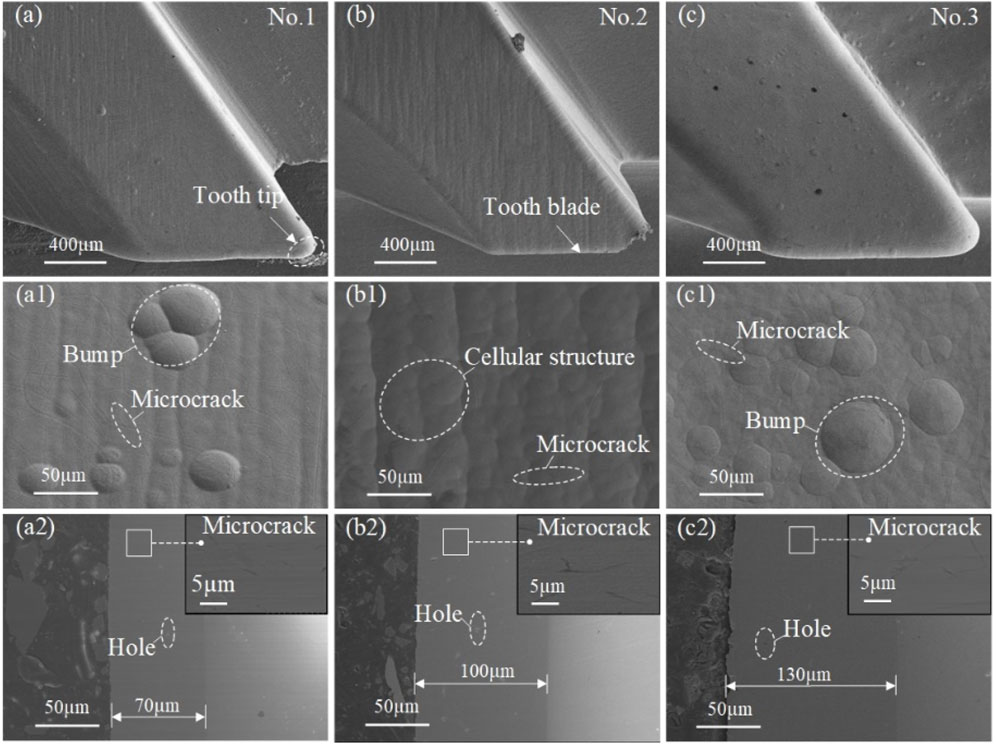
FIGURE 6. Structure of the spindle hook teeth and the microscopic morphology of the hook tooth coating surface and section: (A–C) No.1–3 spindle hook teeth, (a1–c1) surface morphology of No.1–3 spindle hook teeth, and (a2–c2) cross-section morphology of No.1–3 spindle hook teeth.
Dot-like protrusions in the overall morphology of No. 1 and 3 spindle hook teeth correspond to the convex hull structure on the surface of No. 1 and 3 spindle hook tooth coatings at this time. The convex hull is caused by the partially cleaned surface of the spindle hook teeth before electroplating or impurity-polluted plating solution (Yu et al., 1990; Mahdavi et al., 2020). The surface of the No. 2 spindle hook tooth coating presents a typical electroplating layer surface morphology with cellular structure. The surface quality of the No. 2 spindle hook tooth coating is satisfactory. The microscopic morphology photos of the cross-section micro-morphology of the coating of the three types of spindle hook teeth are shown in Figure 6(a2), 6 (b2), and 6 (c2). Evident microcracks and holes can be observed in the cross section of the coating of the three types of spindle hook teeth. The appearance of microcracks is attributed to the release of residual stress during the electroplating process, while the presence of holes is related to the hydrogen produced by the side reaction (hydrogen evolution reaction) during the electroplating process (Yu et al., 1990). The coating thickness of No. 1, 2, and 3 spindle hook teeth is about 70, 100, and 130 μm, respectively.
3.3 Wear failure changes of spindle hook teeth at different installation positions
Scanning electron microscopy was used to characterize the wear changes of hook teeth in the field test (Figure 7). The three types of spindle hook teeth all show a “trapezoid” wear morphology at different installation positions. The area of the “trapezoid” on the surface of hook teeth gradually increases with the increase of field working area. Evident wear on the surface of the hook teeth of three types of spindles installed in the upper part is absent and slight wear is observed on the surface of the hook teeth of No. 1 and 2 spindles installed in the middle part when the spindle picking area reaches 133.33 ha. The hook teeth of No. 1 and 2 spindles installed on the upper part show slight wear and the wear on the hook teeth of the No. 3 spindle was unclear when the spindle picking area reaches 266.66 ha. Evident wear phenomena were observed on the surface of the hook teeth of the three types of spindles installed in the middle and lower parts. The surface of the three types of spindle hook teeth at different installation positions demonstrated wear when the spindle picking area reached 400 ha. The surface of the three types of spindle hook teeth at different installation positions showed serious wear when the spindle picking area reached 533.33 ha. The wear of the hook teeth of the three kinds of spindle samples first occurred at the tip and edge of the hook teeth. The wear area of the No. 3 spindle hook teeth at different installation positions is smaller than that of No. 1 and 2 spindles under different working areas. The high hardness and thickness of the hook tooth coating of the No. 3 sample can protect the hook tooth of the spindle from wear for a long time.
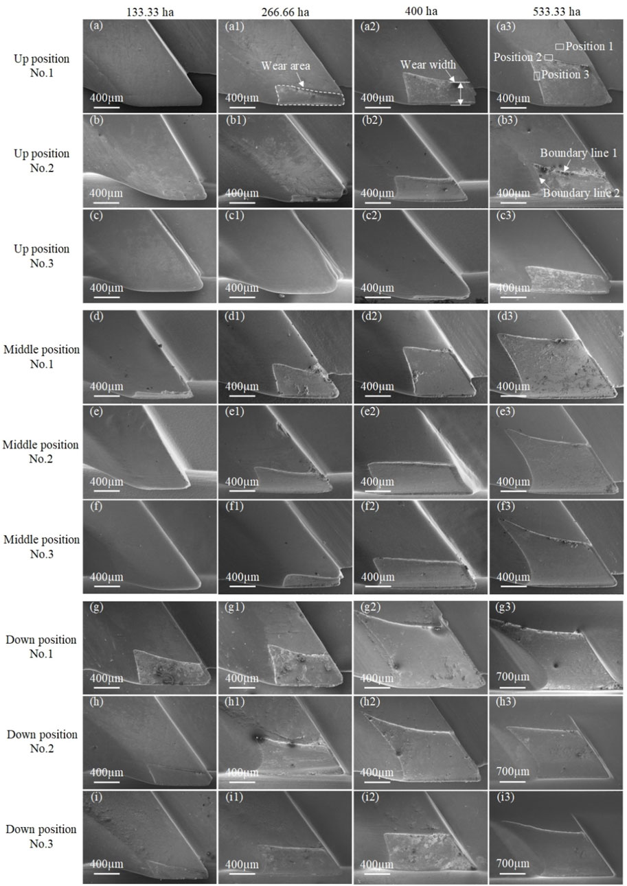
FIGURE 7. Wear variation of No. 1–3 spindle hook teeth under different height locations and working area conditions: wear variation of No. 1–3 spindle hook teeth under different height locations and different working area conditions when the working area is (A–I) 133.33 ha, (a1–i1) 266.66 ha, (a2–i2) 400 ha, and (a3–i3) 533.3 ha.
Curves of the wear area and width of the hook teeth with the installation position are shown in Figures 8A–C and 8(a1)–8(c1) to explore the influence of the field operation area of the spindle on the wear area and width of the hook teeth of the three kinds of spindles. The wear area of the three types of spindle hook teeth at different installation positions exhibited an approximate exponential change, and the wear width presented an approximate linear change. The increase of wear area and width of the three types of spindle hook teeth at different installation positions showed a trend of slow to fast with the increase of the field operation area. The hardness test results demonstrated that the hardness of the coating on the surface of the spindle hook tooth is about two times that of the substrate. The spindle hook tooth matrix is exposed during the field operation when the coating on the surface of the spindle hook tooth wears out. Rapid wear will occur during the continuous field operation because of the low hardness of the matrix that loses coating protection. At the same time, the microstructure analysis of the wear failure of the spindle hook teeth showed that evident fatigue spalling exists at the wear failure boundary of the coating. According to the literature, fatigue spalling of the coating will further accelerate the wear failure of the coating (Korzynski et al., 2009a; Imaz et al., 2014; Zhang et al., 2014; Chen et al., 2020a). Therefore, the wear area and width of the spindle hook teeth gradually accelerate. The comparison of changes in the three kinds of spindles at different installation positions exhibited that the wear area and width of the No. 3 spindle are always smaller than those of No. 1 and 2 spindle hook teeth during field operation. However, the difference between the wear area and width between No. 2 and 3 spindles gradually decreases with the increase of the field operation area. The coating can improve the wear resistance of the spindle hook teeth and prolong the service life of the spindle in the field. The thick coating of the No. 3 spindle can protect the hook teeth from wear for a long time in the early stage of wear; hence, the wear area and width between the No. 3 and 2 spindles are very different in the early stage of wear. However, the wear rate of the hook teeth of the No. 3 spindle gradually accelerated and the wear area and width gap between the No.3 and No.2 spindles gradually decreased with the increase of the field working area of the spindle because of the poorer coating quality of the No. 3 spindle compared with that of the No. 2 spindle. The coating quality of the spindle hook teeth exerts a certain influence on the wear resistance of the hook teeth during field operation.
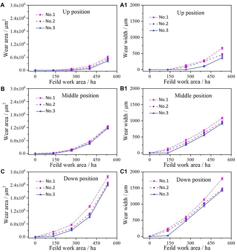
FIGURE 8. Variation curve of wear area and width of No. 1–3 spindle hook teeth under different working area conditions and height locations: variation curve of (A–C) wear area and (a1–c2) wear width of No. 1–3 spindle hook teeth at different height locations.
Figures 9, 10 illustrate the influence of the installation position on the wear area and width of the hook teeth of the three kinds of spindles. The wear area and width of the hook teeth of the three kinds of spindles gradually increase from top to bottom under the same working area. The wear area and width of No. 1 spindle hook teeth are the largest while those of No. 3 spindle hook teeth are the smallest in different working areas and installation positions. This wear change is also related to the thickness of the hook tooth coating. The wear area of the hook teeth of the No. 1 spindle at different installation positions showed a trend of slow to fast in the top–down direction, that is, the wear area of the hook teeth between the upper and middle parts changes slowly and that between the middle and lower parts changes rapidly under the condition of the same field working area. The wear area of hook teeth of No. 2 and 3 spindles in the field operation of in 133.33 and 533.33 ha in the direction of top–down installation position also shows a trend of slow to fast. Meanwhile, the wear area of hook teeth of No. 2 and 3 spindles in the field operation of 266.66 and 400 ha gradually increases with the decrease of installation position, thereby indicating that a negative correlation exists between the installation position of the spindle and the wear area. The comparison of changes of the wear width of the cast teeth at different installation positions in the same working area of the three kinds of spindles demonstrated that the linear change of the wear width of the hook teeth of the No. 1 spindle from the top–down installation position is negatively correlated with the installation position when the field operation is 133.33, 266.66, and 400 ha. Meanwhile, the change of the wear width of the hook teeth of the No. 1 spindle from top to bottom is slow and then fast when the field operation is 533.33 ha. The linear change of the wear width of the No. 2 spindle hook teeth is negatively correlated with the installation position under different working areas. The upper and middle spindle pick hook teeth are worn due to the No. 3 spindle pick hook teeth in the field operation of 133.33 ha (as shown in Figure 7). At this time, the wear width of the spindle hook teeth from the middle to lower direction shows a negative linear change. The linear change of the wear width of the hook teeth of the No. 3 spindle is also negatively correlated with the installation position when the field operation is 266.66, 400, and 533.33 ha. However, the difference between the wear widths of No. 1 and 2 spindle hook teeth gradually increases and that between the wear widths of No. 3 and 2 spindle hook teeth gradually decreases under the conditions of different installation positions and the same working area. Note that the most evident change in the lower installation spindle indicated that the change rate of the hook tooth wear width of the No. 3 spindle gradually accelerates with the increase of the working area. This change phenomenon is also related to the quality of the hook tooth coating.
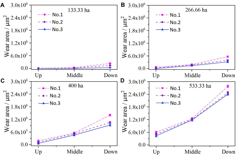
FIGURE 9. Variation curve of wear area of No. 1–3 spindle hook teeth under different height locations when the working area is (A) 133.33 ha, (B) 266.66 ha, (C) 400 ha, and (D) 533.33 ha.
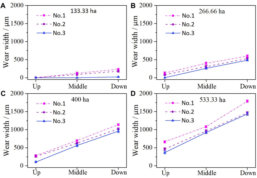
FIGURE 10. Variation curve of wear width of spindle hook teeth under different installation locations when the working area is (A) 133.33 ha, (B) 266.66 ha, (C) 400 ha, and (D) 533.33 ha.
3.4 Wear failure analysis of spindle hook teeth at different installation positions
The wear failure morphology of the spindle hook teeth at different installation positions was characterized using scanning electron microscopy. Three different positions on the hook teeth of three kinds of spindles with different installation positions (as shown in Figure 7[a3]) were selected for analysis when the field operation area reached 533.33 ha. The three selected positions corresponded to the coating surface, wear boundary line 1, and wear boundary line 2 (as shown in Figure 7[b3]). The results are presented in Figures 11–13. Evident micro-cracks and scratches can be observed on the surface of the coating of the three types of spindle hook teeth at three installation positions. The existence of micro-cracks is related to the inevitable residual stress in the electroplating process of the spindle, and scratches are a typical abrasive wear phenomenon. Combined with the field conditions, this phenomenon is mainly due to the plastic deformation and furrows caused by small hard particles in field sliding on the surface of the spindle coating. The comparison of the three installation parts demonstrated that the coating surface of the middle and lower installation spindles exhibits more scratches and the surface condition is more complicated than the upper installation spindle surface. Therefore, the worse working conditions of the middle and lower spindles are consistent with the larger wear failure area and width of the hook teeth of the middle and lower spindles than those of the upper spindles during field operation. The observation of the microstructure of wear boundary lines 1 and 2 of the three types of spindle hook teeth at the three installation sites indicated that evident coating peeling exists at the wear failure boundary line. According to the working condition of the spindle, periodic high-frequency collision will occur between the spindle and cotton stalk in the process of field operation (Dzierwa et al., 2008; Korzynski et al., 2009b). The coating of the spindle will be fatigued and result in fatigue spalling of the coating in the periodic high-frequency collision because many defects, such as microcracks and holes, exist in the coating of the spindle (Korzynski et al., 2009a; Imaz et al., 2014; Zhang et al., 2014; Chen et al., 2020b). The microstructure of the substrate surface after the failure of the three types of spindle coating at three positions demonstrated that additional evident scratches exist on the substrate surface likely due to the abrasive wear phenomenon caused by the sliding of hard particles on the substrate surface. At the same time, many small particles on the surface of the substrate after the coating failed were observed microscopically. The results are shown in Figure 14A. These particles are irregularly distributed on the surface of the substrate, and the composition of particle elements of was examined with an energy spectrum analyzer. The results are shown in Figure 14B. The composition of these particle elements is mainly iron and oxygen. These particles are produced by the oxidation wear of the matrix exposed to the air after the failure of the hook tooth coating (Bensalah et al., 2009; Cellard et al., 2009; Purkayastha and Dwivedi, 2014; Junior et al., 2019). In summary, the damage on the spindle hook teeth is caused by abrasive, fatigue and oxidation wear.
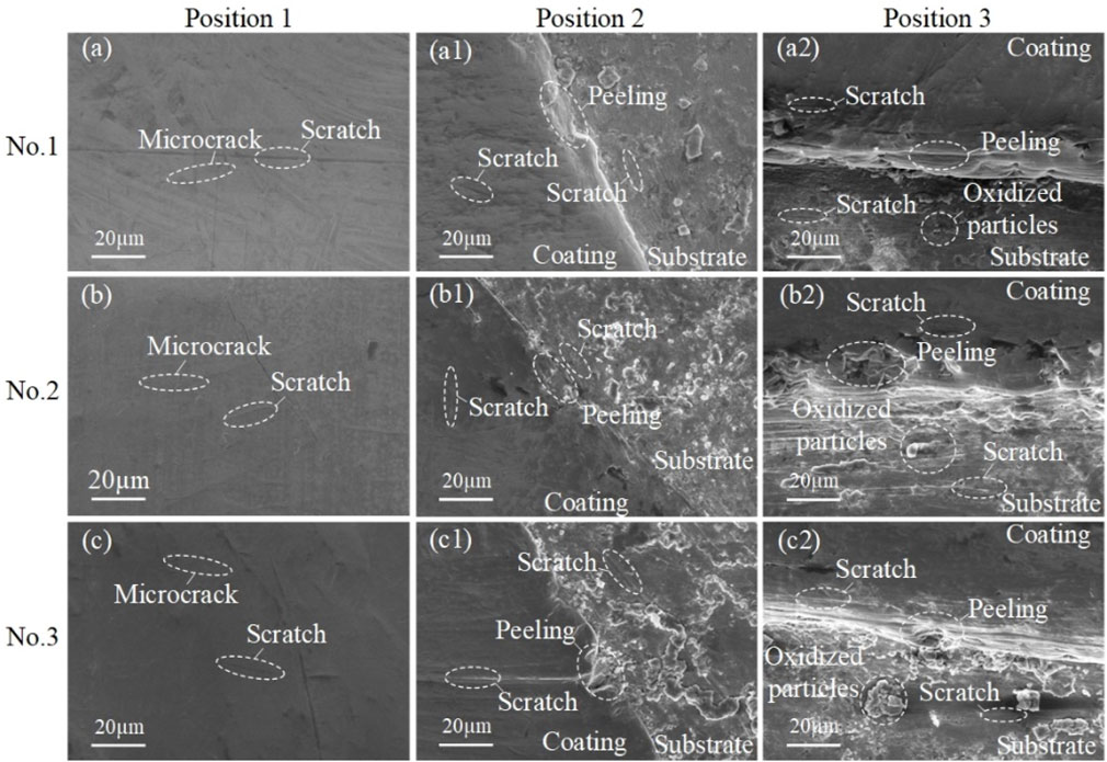
FIGURE 11. Wear morphology of No. 1–3 spindle hook teeth on the upper positions (A–C) 1, (a1–c1) 2, and (a2–c2) 3.
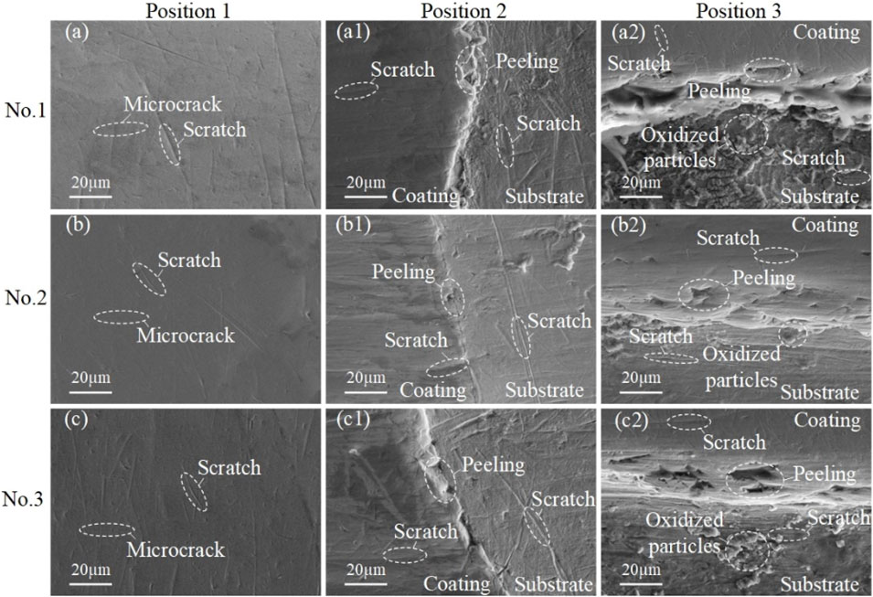
FIGURE 12. Wear morphology of the spindle hook teeth on the middle positions (A–C) 1, (a1–c1) 2, and (a2–c2) 3.
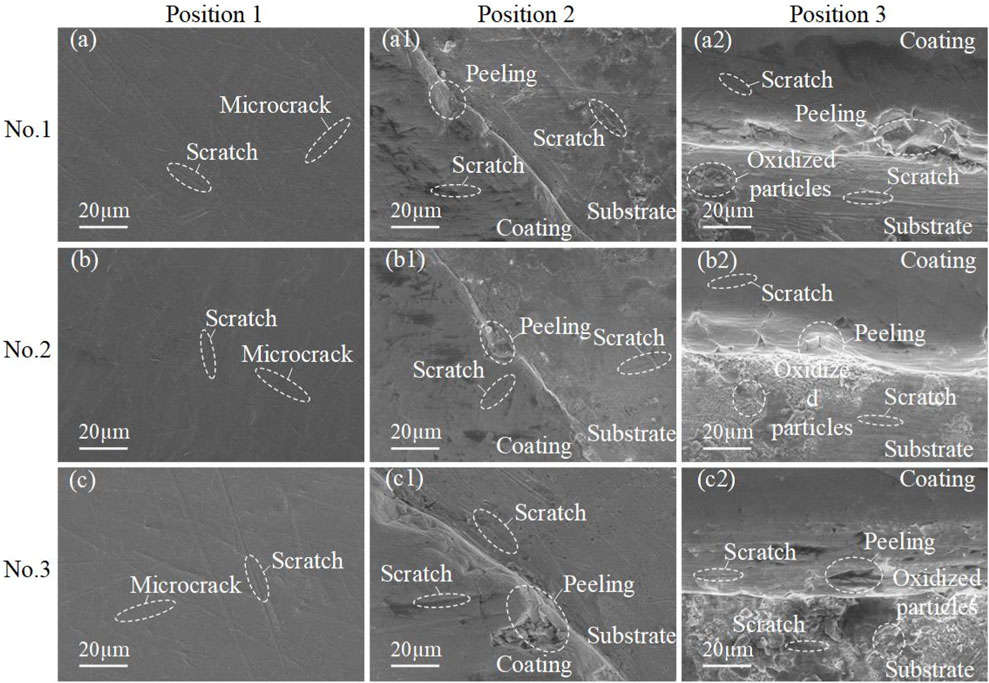
FIGURE 13. Wear morphology of the spindle hook teeth on the lower positions (A–C) 1, (a1–c1) 2, and (a2–c2) 3.
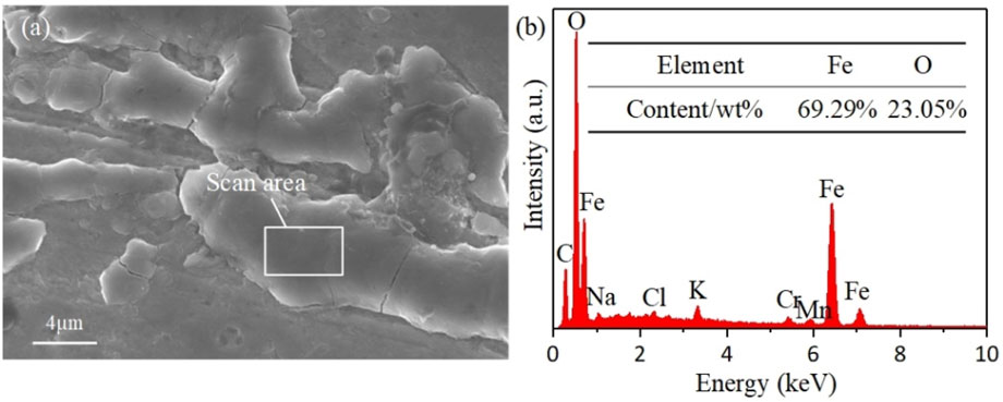
FIGURE 14. (A) Microscopic morphology and (B) EDS analysis of oxidized particles on the substrate surface.
4 Conclusion
(1) The hardness test results showed that the average hardness of the hook tooth coating of No. 1, 2, and 3 spindle samples was 963.2, 973.2, and 1033.6 HV0.1 and the average hardness of the substrate was 438.3, 463.7, and 482.0 HV0.1, respectively. The surface structure of the hook tooth and the microstructure of the coating surface were characterized via scanning electron microscopy. The results showed that microcrack defects exist on the surface of the hook tooth coating. A convex hull structure was observed on the surface of the hook tooth coating of No. 1 and 3 spindle samples. The surface of the hook tooth coating of the No. 2 spindle sample was a cellular structure, and its surface quality was satisfactory. Defects, such as microcracks and micropores, exist in the cross section of the spindle hook tooth coating. The thickness of the hook tooth coating of 3 types of spindles is between 70 and 130 μm, and the thickness of the hook tooth coating of the No. 3 sample is about 130 μm.
(2) The comparison of hook teeth during field operation at different installation positions of the spindle showed that the wear failure first occurs at the tip and edge of the hook teeth. The wear area and width of the hook teeth of spindle samples installed at different positions gradually increase with the increase of the field operation area. The wear area changes exponentially, and the wear width changes linearly. The wear failure rate of the hook teeth is fast when the installation position is close to the lower part of the spindle. The wear area and width of the hook teeth gradually increase with the decrease of the installation position of the spindle under the same field working area. The negative correlation of the wear area and width of the hook teeth with the installation height of the spindle indicated that the wear between the spindle and the cotton is not the main cause of the wear failure of the hook teeth.
(3) Scanning electron microscopy was adopted to characterize the wear failure morphology at three different positions on the surface of the hook teeth of the spindle sample at different installation positions. The results demonstrated that many irregular scratches exist on the coating and substrate surface of the hook teeth of the spindle sample and evident coating peeling occurs on the wear boundary. Additional oxide particles caused by oxidation wear appeared on the surface of the hook teeth substrate after the coating was worn. The results showed that the wear failure of the hook teeth of the spindle sample is mainly caused by abrasive, fatigue, and oxidation wear.
Data availability statement
The raw data supporting the conclusion of this article will be made available by the authors, without undue reservation.
Author contributions
YuW: Writing–original draft, Writing–review and editing, Conceptualization, Formal Analysis, Methodology, Project administration, Resources, Software. ZL: Writing–original draft, Writing–review and editing, Data curation, Funding acquisition, Investigation, Supervision, Validation, Visualization. YG: Project administration, Writing–review and editing. HZ: Project administration, Writing–review and editing. PZ: Validation, Writing–review and editing. YoW: Conceptualization, Writing–review and editing. JY: Data curation, Writing–review and editing.
Funding
The author(s) declare financial support was received for the research, authorship, and/or publication of this article. This work was financially supported by the Corps Major Scientific and Technological Projects (Grant Number: 2018AA008), and the Corps Key Field Innovative Team Building Project (Grant Number: 2019CB006).
Conflict of interest
Authors PZ, YoW, JY, YuW, and ZL were employed by ShanDong Swan Cotton Industrial Machinery Stock Co., China and Xinjiang Swan Modernization Agricultural Machinery Equipment Co, China.
The remaining authors declare that the research was conducted in the absence of any commercial or financial relationships that could be construed as a potential conflict of interest.
Publisher’s note
All claims expressed in this article are solely those of the authors and do not necessarily represent those of their affiliated organizations, or those of the publisher, the editors and the reviewers. Any product that may be evaluated in this article, or claim that may be made by its manufacturer, is not guaranteed or endorsed by the publisher.
References
Amanov, A., Sembiring, J. P. B. A., and Amanov, T. (2019). Experimental investigation on friction and wear behavior of the vertical spindle and V-belt of a cotton picker. Materials 12 (5), 773. doi:10.3390/ma12050773
Bensalah, W., Elleuch, K., Feki, M., Wery, M., and Ayedi, H. F. (2009). Mechanical and abrasive wear properties of anodic oxide layers formed on aluminium. J. Mater. Sci. Technol. 25 (4), 508.
Bi, X. (2007). Study on work mechanism of cotton picker level spindles (Shihezi: Shihezi University). [ master's thesis]. doi:10.7666/d.y1164989
Cellard, A., Garnier, V., Fantozzi, G., Baret, G., and Fort, P. (2009). Wear resistance of chromium oxide nanostructured coatings. Ceram. Int. 35 (2), 913–916. doi:10.1016/j.ceramint.2008.02.022
Chen, T., Zhang, H., and Wang, L. (2020a). Research and experiment on the movement characteristics of the picking mechanism of the horizontal spindle picking cotton picker. J. Chin. Agric. Mech. 41 (2), 19–25. doi:10.13733/j.jcam.issn.2095-5553.2020.02.04
Chen, T. G., Zhang, H. W., Wang, L., Zhang, L. C., Wang, J., et al. (2020b). Optimization and experiment of picking head transmission system of horizontal spindle type cotton picker. Trans. Chin. Soc. Agric. Eng. 36 (17), 18–26. doi:10.11975/j.issn.1002-6819.2020.17.003
Dzierwa, A., Pawlus, P., and Reizer, R. (2008). Surface topography of chromium coatings after pneumatic ball peening. Key Eng. Mater. 381, 113–116. doi:10.4028/www.scientific.net/kem.381-382.113
Gu, Y., Zhang, H., Fu, X., Wang, L., Shen, Z., Wang, J., et al. (2021). Experimental wear behavior analysis of coated spindle hook teeth under real harvesting work conditions. Materials 14 (10), 2487. doi:10.3390/ma14102487
Gu, Y., Zhang, H., Fu, X., Wang, L., Wang, J., Cai, Y., et al. (2022). Comparative analysis of the wear performance of spindle hook teeth during fieldwork. J. Tribol. 144 (1), 011706. doi:10.1115/1.4052636
Imaz, N., Ostra, M., Vidal, M., Díez, J. A., Sarret, M., and García-Lecina, E. (2014). Corrosion behaviour of chromium coatings obtained by direct and reverse pulse plating electrodeposition in NaCl aqueous solution. Corros. Sci. 78, 251–259. doi:10.1016/j.corsci.2013.10.005
Junior, M. D. O., Costa, H. L., Junior, W. S., and De Mello, J. D. B. (2019). Effect of iron oxide debris on the reciprocating sliding wear of tool steels. Wear 426, 1065–1075. doi:10.1016/j.wear.2018.12.047
Korzynski, M., Dzierwa, A., Pacana, A., and Cwanek, J. (2009a). Fatigue strength of chromium coated elements and possibility of its improvement with ball peening. Surf. Coatings Technol. 204 (5), 615–620. doi:10.1016/j.surfcoat.2009.08.049
Korzynski, M., Pacana, A., and Cwanek, J. (2009b). Fatigue strength of chromium coated elements and possibility of its improvement with slide diamond burnishing. Surf. Coatings Technol. 203 (12), 1670–1676. doi:10.1016/j.surfcoat.2008.12.022
Li, H., Fu, X., Wang, H., Zhang, H., Gu, Y., Du, X., et al. (2022a). Research on the wear characteristics of the hook teeth of cotton pickers. Coatings 12 (6), 762. doi:10.3390/coatings12060762
Li, H., Fu, X., Zhang, H., Zhang, L., Wang, M., et al. (2022b). Analysis and experiment of dynamic picking process of spindle of cotton picker. Agriculture 12 (9), 1346. doi:10.3390/agriculture12091346
Li, W. C., Qiao, Y. Y., Deng, Y. M., Liu, X. M., and Zhang, H. W. (2018). Valuation and analysis of hook tooth wear for cotton picker spindle. J. Chin. Agric. Mech. 39 (3), 11–14. doi:10.13733/j.jcam.issn.2095-5553.2018.03.003
Lunarska, E., Nikiforow, K., Wierzchon, T., and Ulbin-Pokorska, I. (2001). Effect of plasma nitriding on hydrogen behavior in electroplated chromium coating. Surf. Coatings Technol. 145 (1-3), 139–145. doi:10.1016/S0257-8972(01)01287-7
Luo, S. L., Zhang, Y. Q., and Ma, S. H. (2018). Wear mechanism analysis on spindle of cotton picker. J. Tarim. Univ. 30 (7), 132–137. doi:10.3969/j.issn.1009-0568.2018.01.017
Mahdavi, S., Allahkaram, S. R., Heidarzadeh, A., and Tavangar, R. (2020). Characteristics and properties of Co–Cr alloy coatings prepared by electrodeposition. Surf. Eng. 36 (9), 966–974. doi:10.1080/02670844.2019.1688012
Meng, F., Chen, N., and Chen, Z. (2016a). Hard chromium coating effects on tribological performances for nonlubricated and lubricated spindle of cotton picker. Proc. Institution Mech. Eng. Part L J. Mater. Des. Appl. 230 (2), 446–453. doi:10.1177/1464420715577234
Meng, F., Chen, Y., Yang, Y., and Chen, Z. (2016b). Friction and wear behavior of electroless nick coating used for spindle of cotton picker. Industrial Lubr. Tribol. 68 (2), 220–226. doi:10.1108/ILT-06-2015-0070
Pina, J., Dias, A., Francois, M., and Lebrun, J. L. (1997). Residual stresses and crystallographic texture in hard-chromium electroplated coatings. Surf. coatings Technol. 96 (2-3), 148–162. doi:10.1016/S0257-8972(97)00075-3
Purkayastha, S., and Dwivedi, D. K. (2014). Abrasive and erosive wear performance of rare earth oxide doped Ni/WC coatings. J. Tribol. 136 (1), 011602. doi:10.1115/1.4025099
Sun, Z., Sun, W., and Lu, G. (2021). Study on surface strengthening of cotton pick-up spindle based on plasma spraying. Hot Work. Technol. 50 (20), 96–99. doi:10.14158/j.cnki.1001-3814.20190227
Wang, L., Nam, K. S., and Kwon, S. C. (2007). Effect of plasma nitriding of electroplated chromium coatings on the corrosion protection C45 mild steel. Surf. Coatings Technol. 202 (2), 203–207. doi:10.1016/j.surfcoat.2007.05.027
Wang, X., Li, Y., Fu, W., et al. (2021). Analysis of meteorological conditions for cotton growth in Xinjiang in 2020. China Cotton 48 (3), 42–44. doi:10.11963/1000-632X.wxjlyc.20210302
Weiss, B., Lefebvre, A., Sinot, O., Marquer, M., and Tidu, A. (2015). Effect of grinding on the sub-surface and surface of electrodeposited chromium and steel substrate. Surf. Coatings Technol. 272, 165–175. doi:10.1016/j.surfcoat.2015.04.009
Wu, B., Zhang, L. X., Zuo, Y. T., and Wei, M. (2013). Research of material elements distribution in cotton picker’s level spindle based on SEM and EDS. J. Agric. Mech. Res. 35 (7), 174–178. doi:10.13427/j.cnki.njyi.2013.07.049
Yu, W. P., Zhang, M. J., and He, Y. D. (1990). The effect of hydrogen on the structural transformation of electroplationg chromium coatings. J. Beijing Univ. Aeronaut. Astronaut. 2, 129–132. doi:10.13700/j.bh.1001-5965.1990.02.018
Zhang, H. (2013). The working mechanism and experimental study of the key components of the cotton picking head of the glue stick roller. Nanjing: Nanjing Agricultural University. doi:10.7666/d.Y2528420
Zhang, Y., Cai, Z., Tian, Y., and Meng, Y. (2018). Improvement of mechanical properties and wear resistance of cotton picker spindle by electromagnetic treatment. Trans. Chin. Soc. Agric. Eng. 34 (7), 31–37. doi:10.11975/j.issn.1002-6819.2018.07.004
Zhang, Y., Ma, S., and Ding, W. (2012). Dynamic analysis on picking process of cotton picker spindle. Trans. Chin. Soc. Agric. Eng. 28 (13), 54–58. doi:10.3969/j.issn.1002-6819.2012.13.009
Zhang, Y., Tian, Y., and Meng, Y. (2021). Wear behavior of spindles of cotton picker in field work. J. Tribol. 143 (2), 021703. doi:10.1115/1.4047790
Zhang, Y., Wang, W., and Liao, J. (2017). Wear failure analysis on spindle of cotton picker. Trans. Chin. Soc. Agric. Eng. 33 (18), 45–50. doi:10.11975/j.issn.1002-6819.2017.18.006
Keywords: cotton picker spindle, hook tooth, wear failure, wear area, wear width
Citation: Wang Y, Li Z, Gu Y, Zhang H, Zhao P, Wang Y and Yang J (2024) Experimental study on wear failure of spindle hook teeth of cotton picker. Front. Mater. 10:1309617. doi: 10.3389/fmats.2023.1309617
Received: 08 October 2023; Accepted: 20 November 2023;
Published: 02 February 2024.
Edited by:
Zhongya Zhang, Chongqing Jiaotong University, ChinaReviewed by:
Viorel Paleu, Gheorghe Asachi Technical University of Iași, RomaniaFemiana Gapsari, University of Brawijaya, Indonesia
Copyright © 2024 Wang, Li, Gu, Zhang, Zhao, Wang and Yang. This is an open-access article distributed under the terms of the Creative Commons Attribution License (CC BY). The use, distribution or reproduction in other forums is permitted, provided the original author(s) and the copyright owner(s) are credited and that the original publication in this journal is cited, in accordance with accepted academic practice. No use, distribution or reproduction is permitted which does not comply with these terms.
*Correspondence: Zhantao Li, eGp0ZWx6dEAxNjMuY29t