 Dingyi Zhang1
 Wenhe Yu
 Xiangyang Hao
 Fenghao Lu
- 1Engineering Research Center of Ministry of Education for Geological Carbon Storage and Low Carbon Utilization of Resources, Beijing Key Laboratory of Materials Utilization of Nonmetallic Minerals and Solid Wastes, National Laboratory of Mineral Materials, School of Materials Science and Technology, China University of Geosciences, Beijing, China
- 2Beijing Trans-universe Space Technology Co., Ltd., Beijing, China
Composite fibers made from aramid III and hydroxylated multiwalled carbon nanotubes (MWCNTs-OH) combine the excellent mechanical and electrical properties of both components, resulting in strong antistatic performance. However, it is of paramount importance to ensure the homogeneous dispersion of multi-walled carbon nanotubes functionalized with hydroxyl groups (MWCNTs-OH) within the aramid III spinning solution and optimize the compatibility between the two constituents to augment the overall performance of the composite fibers. To this end, this investigation successfully accomplished the dispersion of MWCNTs-OH in the spinning solution and probed the dispersion mechanism using molecular dynamics simulations. Moreover, composite fibers, comprising 2.4 weight percent MWCNTs-OH, were initially fabricated using the wet spinning method. These fibers displayed a uniform texture and a tensile strength of 1.210 GPa, signifying a noteworthy enhancement of 113.25% in comparison to the strength prior to modification. With respect to thermal behavior, the fibers exhibited a mass reduction of 21.24% within the temperature range of 0°C–538°C. In the temperature interval from 538°C to 800°C, the mass loss diminished to 10.31%, representing a substantial 71.03% reduction when compared to the unmodified state. Remarkably, even when subjected to temperatures exceeding 800°C, the composite fibers retained a residual mass of 68.45%, indicating a notable 61.17% increase from their initial condition. In terms of electrical properties, the fibers exhibited a specific resistance (ρ) of 3.330 × 10⁹ Ω cm, demonstrating effective antistatic behavior. In summary, the antistatic composite fibers studied in this paper can effectively mitigate the hazards of static electricity in various applications, including military protection and engineering equipment in both military and civilian fields.
1 Introduction
Although chemical fibers offer the advantages of being lightweight, corrosion-resistant, and high-strength, they are prone to static electricity, particularly in dry environments (Li et al., 2004; Zhang et al., 2010; Liu et al., 2023). This propensity can lead to unnecessary harm to users of military protection and engineering equipment, significantly impacting the use of high-performance fibers in harsh conditions. Aramid III (F3) incorporates a heterocyclic structural element into the molecular framework of poly-p-phenylene terephthamide (PPTA), resulting in enhanced mechanical characteristics in comparison to PPTA fibers. The production of F3 fibers involves a ternary copolycondensation process conducted at low temperatures, facilitated by the inclusion of a designated solvent (Liu et al., 2023). Carbon nanotubes (CNTs), as one-dimensional carbon nanomaterials, have garnered attention due to their high aspect ratio, superconductivity, excellent thermal conductivity, and high strength (Liang and Cheng, 2018; Cao et al., 2020). Currently, hydroxyl groups have been successfully introduced to carbon nanostructures, including spherical fullerenes (Ma and Srpsa, 2020), carbon fibers (Stephenson et al., 2006), and multiwalled carbon nanotubes (MWCNTs) (Gong et al., 2000).
Xu et al. (Duan et al., 2019) documented a process in which sulfonated carbon nanotubes (SCNTs) and an organic antistatic agent (OAA) underwent treatment to create a composite conductive layer. It was observed that when the addition of this composite ranged from 0.5 to 2 wt%, the resulting fibers exhibited outstanding antistatic characteristics, and the resistivity remained nearly unaffected by the stretching of the fibers. Gürakın et al. (Xu et al., 2021) reported that the addition of 15 wt% polyester-ether copolymer as an antistatic agent reduced the resistivity of polyethylene terephthalate from 1015 Ω cm to 109 Ω cm. Rudolf Hufenus et al. (Gürakın et al., 2019) employed melt spinning to create dual-component antistatic fibers by incorporating conductive fillers such as carbon black into the fiber-forming polymer. Wet spinning is also a crucial method for producing these composite fibers (Hufenus et al., 2020). Xu Ziao et al. (Hao et al., 2013) successfully manufactured light-colored antistatic ATZO@TiO2/PAN fibers using the wet spinning process.
In this paper, we initially used molecular dynamics (MD) simulations to investigate the dispersion mechanism of hydroxylated MWCNTs (MWCNTs-OH) in the F3 spinning solution (Xu et al., 2023). MD simulations provide a means to investigate multiple factors influencing the mechanical attributes of materials, establishing connections between mechanical behavior, structural alterations, and molecular interactions and motion in nanocomposite systems (Jahangiri and Ozden-Yenigun, 2018). As a result, MD simulation techniques have exerted a substantial influence on domains like materials science, biology, chemistry, and medicine (Zang, 2019).
In this study, we used the consistent valence force field (CVFF) (Zhao, 2008) and selected the canonical ensemble (Wang et al., 2018) to establish a dispersion model for calculation, discussing parameters such as the number of hydrogen bonds, intermolecular bonding energy, trends in the twist angle of large molecules, and radial distribution function (RDF) within the system. We chose to disperse MWCNTs-OH in N, N-dimethylacetamide (DMAC) to create an antistatic agent, and then mixed aramid III and MWCNTs-OH in specific proportions, followed by ultrasonic treatment to obtain a homogeneous solution (Robert Charles et al., 1999). Subsequently, the solution was extruded through a microporous plate and solidified into fibers using a coagulation bath. Subsequent to drying, stretching, and shaping procedures, we successfully manufactured high-strength composite fibers comprising F3/MWCNTs-OH. Nevertheless, certain challenges persist in the production of these composite fibers, specifically regarding the achievement of a consistent dispersion of MWCNTs-OH and the optimization of process parameters to enhance performance. To address these issues, we conducted characterizations of the spinning solution employing optical microscopy and laser micro-Raman spectroscopy. Next, the MWCNTs-OH/F3 spinning solution was prepared, and antistatic fibers were produced using the wet spinning technology. Finally, the microstructure of the fibers was observed using a scanning electron microscope (SEM), and the mechanical properties of the fibers were tested using a universal testing machine. The thermal behavior was measured with a thermogravimetric analyzer (TGA), and their electrical resistance was determined using an electrometer.
2 Materials and methods
2.1 Materials
The primary experimental materials included F3 spinning solution (7wt%, Institute of Polymer Science and Engineering, Department of Chemical Engineering, Tsinghua University), DMAC (98% analytical purity, Macklin Co., Ltd.), deionized water (South China High-Tech Group Environmental Protection Biotechnology Co., Ltd.), MWCNTs (99%, Tianjin Suiheng Technology Co., Ltd. length: 8–10 nm; external diameter: 3–4 nm; internal diameter: 1–2 nm), and MWCNTs-OH (99%, Tianjin Suiheng Technology Co., Ltd. length: 8–10 nm; external diameter: 3–4 nm; internal diameter: 1–2 nm).
2.2 Spinning solution preparation
As the solvent for F3 spinning solution was DMAC, MWCNTs-OH were first pre-mixed in DMAC solvent. Following a 30-min ultrasonic treatment to ensure even dispersion in DMAC, solutions were prepared containing 2 wt%, 3 wt%, and 4 wt% of MWCNTs-OH in DMAC. Subsequently, these MWCNTs-OH/DMAC solutions were combined with the aramid III/DMAC spinning solution at a ratio of 1.5:1.0 to generate homogeneous aramid III/MWCNTs-OH/DMAC spinning solutions, featuring MWCNTs-OH mass fractions of 1.2 wt%, 1.8 wt%, and 2.4 wt%. Figure 1A shows the superior stability of MWCNTs-OH dispersion in DMAC compared to MWCNTs, while Figure 1B illustrates the initial layering observed upon adding the MWCNTs-OH/DMAC dispersion solution to the F3 spinning solution. After stirring and ultrasonic bath (400 W, 40 kHz), a homogeneous spinning solution was obtained, as depicted in Figure 1C.
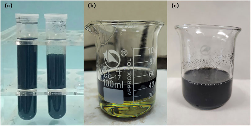
FIGURE 1. Dispersion of CNTs. (A) Comparison of MWCNTs-OH and MWCNTs dispersion in DMAC; (B) MWCNTs-OH dispersion poured into the F3 spinning solution; (C) Homogeneous F3/MWCNTs-OH spinning solution.
2.3 MD simulation
This study employed the MD method to simulate the dispersion characteristics and interactions of MWCNTs-OH with a hydroxylation rate of 10% in the F3 system, with the omission of considering the influence of the DMAC solvent on the system. The LAMMPS program was utilized for molecular simulation, and the CVFF force field was chosen to describe the system interactions. In a simulation box with a volume of 1,475 nm3, the vertical velocity algorithm was utilized, the integration time step was set to 1.0 fs, and temperature and pressure control were achieved using a Nos-Hoover thermostat. The van der Waals cutoff for electrostatic interactions was set at 1.2 nm, and the particle-particle particle-mesh (PPPM) algorithm was employed to simulate long-range electrostatic interactions. After conducting the structural energy minimization procedure, a relaxation process was executed using the canonical ensemble (NVT). During this process, the model temperature was incrementally raised from 10 K to 300 K. Following this, an additional 4 ns simulation was conducted at 300 K within the NVT ensemble, and data was recorded during the final 2 ns. Figure 2 illustrates the MD model.
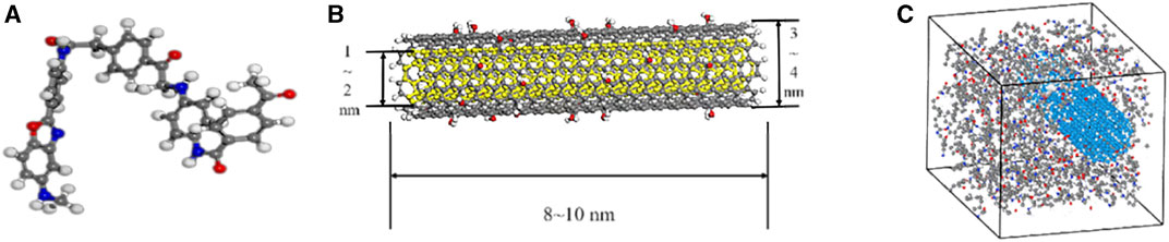
FIGURE 2. Simulation model. (A) Molecular model of F3; (B) molecular model of MWCNTs-OH; (C) simulation unit model of the F3/MWCNTs-OH spinning solution.
2.4 Wet spinning of F3 fibers
In this experiment, the F3 spinning solution was combined with a DMAC aqueous solution with a coagulation bath concentration of 20wt%. The wet spinning equipment was constructed, incorporating an injection pump, a winding device, and other essential components. The spinning needle’s inner diameter was determined to be 0.84 mm. A visual representation of the wet spinning process can be found in Figure 3. The extrusion speed was set at 1 mL/min, and the winding speed ranged from 1.5 to 1.8 m/min. Subsequently, the fibers were soaked in water for 24 h and then air-dried for an additional 24 h to yield the golden F3 fibers. The detailed fiber production process is depicted in Figure 3.
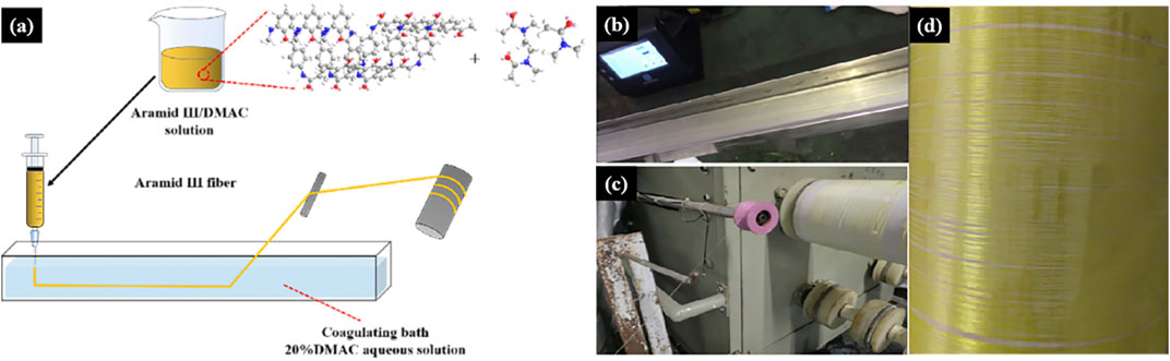
FIGURE 3. Wet spinning process. (A) Spinning process diagram; (B–D) actual spinning process.
2.5 Wet spinning of composite fibers
In this experiment, we utilized the prepared F3/MWCNTs-OH/DMAC spinning solution in conjunction with a DMAC aqueous solution with a coagulation bath concentration of 20wt%. The wet spinning setup was assembled, comprising an injection pump, a winding device, and a coagulating bath. The spinning needle had a precisely measured inner diameter of 0.84 mm, and the visual representation of the wet spinning process is presented in Figure 4A. We set the extrusion speed at 4 mL/min and maintained a winding speed in the range of 3.5–3.8 m/min. Subsequently, the fibers were immersed in water for a duration of 24 h and subsequently air-dried for an additional 24 h to yield the black F3-based fibers. The comprehensive fiber production process is elaborated in Figures 4B–D.
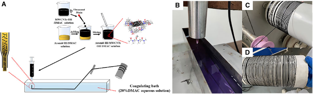
FIGURE 4. F3/MWCNTs-OH composite fibers. (A) Wet spinning process; (B–D) experimental process of wet spinning.
2.6 Measuring resistance using the electric bridge method
The electric bridge method is a straightforward and precise technique for assessing resistance, with its underlying principle depicted in Figure 5.
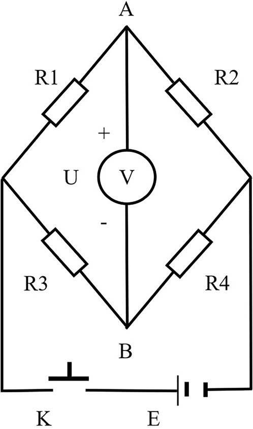
FIGURE 5. Measuring the resistance of short chemical fibers by the electric bridge method. R1–Resistance box; R2–Test box; R3 and R4–Resistance; U–Voltmeter; K–Button switch; E–DC power supply.
To measure the specific resistance, the first step involved placing the fibers inside the test box. According to electrical principles, when R1 equals R2 as shown in Figure 5, the voltmeter reading will be 0. To ascertain the resistance of the fibers, a gradual adjustment of the resistance box is required to minimize any disparity in resistance. When the voltmeter registers a reading of 0, it indicates that the potentials at points A and B are in equilibrium, signifying that the resistance box value corresponds to the resistance of the fibers. Subsequently, the specific resistance of the fibers can be calculated using Equation 1, where ρ (Ω·cm) represents the specific resistance of the fibers, R (Ω) is the resistance of the tested object, S (cm2) is the cross-sectional area of the tested object, and L (cm) is the length of the tested object. Owing to the difficulty of measuring the individual short fibers’ cross-sectional area and length, this study employed 15 grams of short fibers, which were evenly placed into the test box and compressed firmly. Inside the test box, two electrode plates were placed, spaced 2 cm apart, each measuring 6 cm in length and 4 cm in width. Consequently, the fibers took the form of a rectangular cuboid with a cross-sectional area of 24 cm2 and a length of 2 cm. The resistance between the two electrode plates was then measured using this approach, and the specific resistance of the fibers was calculated based on Equation 1. As it was not practical to completely fill the test box with short fibers, the specific resistance, calculated using Equation 1, had to be multiplied by the standard filling factor of the fibers, as described in Equation 2. The standard filling factor of fibers is the ratio between the fiber mass in the experiment (fixed at 15 g) and the mass of fibers required to completely fill the test box, where 24 (cm2) represents the cross-sectional area of the test box, and 2 (cm) corresponds to its length. The final specific resistance of the fibers was then determined according to Equation 3.
2.7 Characterization
The equipment employed in this study comprised the following: an optical microscope (BX50, Olympus Group, Japan), scanning electron microscope (SEM, JSM-7001F, JEOL Ltd., Japan), a universal testing machine (68TM-30, Instron Company, USA) tensile rate: 2 mm/min, thermal gravimetric analyzer (TGA, Q5000IR, TA Instruments, USA) Experimental temperature range: room temperature-800°C; experimental heating rate: 10°C/min; experimental test atmosphere: nitrogen, X-ray diffractometer (XRD, D8 ADVANCE, BRUKER Company, Germany), laser micro-Raman spectrometer (LabRAM HR Evolution, HORIBA Scientific, France), and a high-resistance electrometer (6517B, Tektronix Inc., USA).
3 Results and discussion
3.1 Optical microscopic image of MWCNTs-OH dispersion in DMAC
Figure 6 displays an optical microscope image of MWCNTs-OH/DMAC dispersion in the F3/DMAC spinning solution. It is evident that, when magnified under the optical microscope, MWCNTs-OH exhibit relatively uniform dispersion in the spinning solution, although there are minor instances of aggregation.
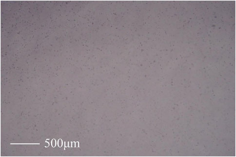
FIGURE 6. Optical microscopic image of MWCNTs-OH/DMAC dispersed in the F3/DMAC spinning solution.
3.2 Raman spectroscopy of the F3/MWCNTs-OH/DMAC spinning solution
To verify the purity of MWCNTs-OH in the F3 spinning solution, Raman spectroscopy analysis was conducted on the spinning solution. The spectra are presented in Figure 7A, clearly indicating the presence of characteristic peaks at 1,196, 1,256, 1,369, 1,448, 1,540, and 1,610 cm–1 associated with F3. With the inclusion of MWCNTs-OH, distinctive peaks at 1,355 cm–1 and 1,584 cm–1 became apparent. These peaks, as evidenced by the Raman spectrum of MWCNTs-OH illustrated in Figure 7B, corresponded to the characteristic features of MWCNTs-OH. Hence, it can be concluded that MWCNTs-OH were indeed present in the F3 spinning solution.
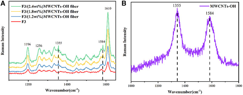
FIGURE 7. Raman spectra. (A) F3/MWCNTs-OH spinning solution; (B) MWCNTs-OH.
3.3 MD simulation of MWCNTs-OH dispersion in the F3 spinning solution
This study primarily centered on examining the interaction between MWCNTs-OH and F3 polymer macromolecules, with the exclusion of any consideration of solvent effects. As a result, we conducted simulations to mimic the real-world dispersion of MWCNTs-OH in F3 using specialized software. As depicted in Figure 8, the software facilitated the simulation of the dispersion modification system, and the figure’s visualization vividly displayed the intimate connection and interaction between the continuous phase and the dispersed phase.

FIGURE 8. Simulation of the dispersion state of MWCNTs-OH in the F3 spinning solution.
This study incorporated simulations to examine the influence of hydrogen bonds within the system. As depicted in Figure 9A, hydrogen bonding was observed between F3 molecules, between F3 and MWCNTs-OH, and also between MWCNTs-OH molecules. Figure 9B demonstrates that the OH-MWCNTs and F3 exhibited a negative binding energy, resulting in relative stability, We know from the figure that the binding energy between OH-MWCNTs and OH-MWCNTs is positive, so the system is unstable, while the binding energy between F3 and F3 is negative, which is a stable system. The integrated system of OH-MWCNTs and F3 in the same system is still stable. In Figure 9C, it is evident that an increase in the content of MWCNTs-OH led to friction between F3 macromolecules and MWCNTs-OH. At the same time, the twist angle of the amide bonds in F3 macromolecules gradually increased, yet it remained below 180°. This observation indicates that the dispersion system leaned towards stability with the inclusion of MWCNTs-OH.
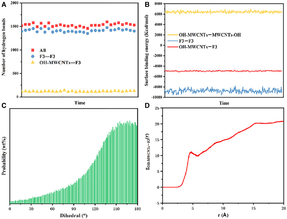
FIGURE 9. MD simulation of the dispersion system. (A) Number of hydrogen bonds in the system; (B) Binding energy between the molecules of MWCNTs-OH in the F3 dispersion system; (C) trend of the twist angle for the polymer macromolecules in the system; (D) RDF of MWCNTs-OH and F3 in the dispersion system.
To further elucidate the nature of the interaction between MWCNTs-OH and F3 molecules, we employed RDF calculations to describe their overall structure in the dispersion system. The RDF (as depicted in Figure 9D) plays a pivotal role in connecting the macroscopic thermodynamic properties of various substances with their intermolecular interactions (Xu et al., 2023). In molecular simulations, the RDF assesses the relationship between the local particle density within a periodic boundary box and the overall density. According to the RDF analysis, MWCNTs-OH and Aramid III displayed interactions at an approximate distance of 5 Å. This interaction primarily stemmed from hydrogen bonds and van der Waals forces, a conclusion that could be substantiated through Raman spectroscopy.
3.4 Composite fiber microstructure
This section investigates the influence of the modified filler content on the surface morphology of the composite fibers. Figures 10a1–a3 illustrate that the F3 fibers exhibit a smooth surface, an almost circular cross-section, and are readily knotable, indicating successful spinning. In Figure 10b1, the surface of the F3/MWCNTs-OH composite fibers becomes somewhat uneven when the MWCNTs-OH content is 1.2wt%, with grooves along the fiber axis, and the structure is not tightly packed. This is because the F3/MWCNTs-OH composite fibers are produced through the wet spinning process, during which the solvent evaporates. The grooves on the surface increase the roughness, which enhances adhesion between the fibers and the matrix in the composite material. In Figure 10b2, the cross-section of the F3/MWCNTs-OH composite fibers remains approximately circular, indicating successful spinning. Figure 10b3 illustrates that even with the incorporation of the brittle material MWCNTs-OH at 1.2wt%, the fibers remain easily knotted, signifying good toughness.
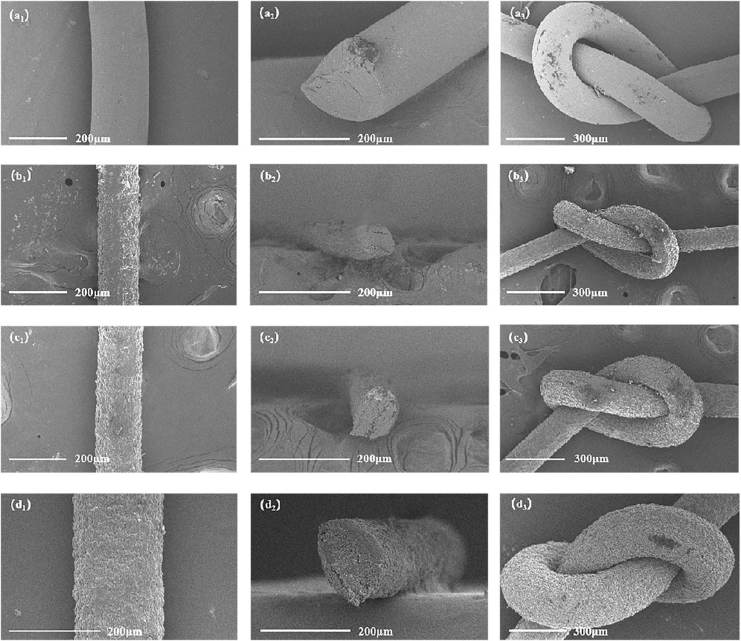
FIGURE 10. SEM images of the F3/MWCNTs-OH composite fibers. (a1)–(a3) F3 fibers; (b1)–(b3) composite fibers with an MWCNTs-OH content of 1.2wt%; (c1)–(c3) composite fibers with an MWCNTs-OH content of 1.8wt%; (d1)–(d3) composite fibers with an MWCNTs-OH content of 2.4wt%.
Moving on to Figure 10c1, when the MWCNTs-OH content is increased to 1.8wt%, the surface of the F3/MWCNTs-OH composite fibers becomes somewhat uneven, with grooves along the fiber axis, and the structure is not tightly packed. This is because the wet spinning process is used, and the solvent evaporates, creating these grooves that enhance surface roughness and adhesion with the matrix. Figure 10c2 shows that the cross-section of the F3/MWCNTs-OH composite fibers remains circular. Figure 10c3 demonstrates that even with the addition of 1.8wt% of brittle MWCNTs-OH, the fibers can still be knotted, indicating a successful orientation of MWCNTs-OH during spinning, resulting in strong toughness.
In the final analysis, as depicted in Figure 10d1, when the MWCNTs-OH content reaches 2.4 wt%, the surface of the F3/MWCNTs-OH composite fibers exhibits some irregularities, characterized by grooves running along the fiber axis. While the arrangement is not entirely compact, there is noticeable improvement. This coarseness can be attributed to the wet spinning process, where the solvent evaporates, resulting in uneven grooves on the fiber surface. These grooves enhance surface roughness, which, in turn, promotes adhesion between the fibers and the matrix. Moving to Figure 10d2, the cross-sectional view of the F3/MWCNTs-OH composite fibers remains circular, and the fibers are relatively closely packed. This does not affect the mechanical properties of the fibers, indicating successful spinning. Finally, Figure 10d3 illustrates that even with the addition of 2.4wt% of brittle MWCNTs-OH, the fibers can still be knotted, indicating the successful orientation of MWCNTs-OH during spinning, resulting in strong toughness.
3.5 XRD analysis
As depicted in Figure 11, the XRD pattern of the F3/MWCNTs-OH composite fibers reveals an absence of crystallization on the fiber surface. In contrast to the control group, new characteristic peaks of MWCNTs-OH emerged in the range of 20°–30° after the addition of MWCNTs-OH. These peaks became more pronounced as the filler content increased, suggesting strong bonding between the filler and the matrix, while the overall fibers retained their amorphous nature.
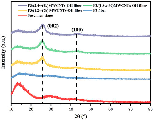
FIGURE 11. XRD analysis of F3/MWCNTs-OH and F3.
3.6 Mechanical performance
Figure 12A presents the stress–strain curves of F3/MWCNTs-OH and F3, illustrating a gradual improvement in mechanical properties with increasing MWCNTs-OH content. This enhancement can be attributed to the addition of the brittle MWCNTs-OH, which not only improved the mechanical properties of the original fibers but also mitigated the yield stage. A comparative analysis of mechanical characteristics at various levels of modified filler content, namely 0, 1.2, 1.8, and 2.4 weight percent (wt%), verified a notable influence of the modified filler content on the mechanical properties, in agreement with the findings from the SEM images. Specifically, with a MWCNTs-OH content of 1.2 wt%, the tensile strength exhibited an increase of 12.35% when compared to the scenario with 0 wt% MWCNTs-OH. At 1.8wt% MWCNTs-OH, the tensile strength increased by 29.87% compared to 0wt% and by 15.59% compared to 1.2wt%. With a 2.4wt% MWCNTs-OH content, the tensile strength increased by 113.25% compared to 0wt%, by 89.46% compared to 1.2wt%, and by 63.91% compared to 1.8wt%. As illustrated in Figure 12B, the rise in MWCNTs-OH content led to a reduction in the tensile strain of the fibers, whereas the tensile strength exhibited an increase. A condensed overview of the test results is provided in Table 1.
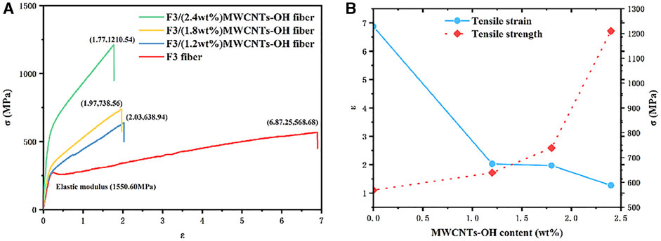
FIGURE 12. Changes in the mechanical properties with different the MWCNTs-OH contents (A) Stress–strain curves of the F3/MWCNTs-OH composite fibers and F3 fibers; (B) Effect on the mechanical properties of the fibers with an increasing MWCNTs-OH content.
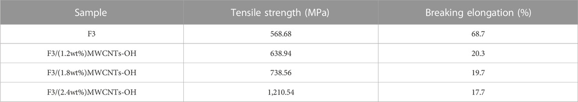
TABLE 1. Mechanical properties of the fibers.
3.7 Thermal performance
Figure 13 illustrates the thermogravimetric analysis results for the antistatic F3/MWCNTs-OH fibers. The TGA curve distinctly shows a decomposition temperature of around 538°C (°C), with the thermal stability of the fibers improving as the MWCNTs-OH content increases. However, when the MWCNTs-OH content reached 1.2wt%, the thermal stability of the fibers was suboptimal prior to reaching the decomposition temperature. This may be attributed to insufficient bonding between the MWCNTs-OH and polymer molecules, a conclusion supported by the variation trend of the twist angle observed in MD simulation. However, even beyond the decomposition temperature, a substantial portion of 64.81% of the composite fibers persisted. With an MWCNTs-OH content of 1.8 wt%, the mass loss ratio of the F3/MWCNTs-OH fibers was 21.24% in the temperature range of 0°C–538°C and 15.68% in the range of 538°C–800°C, with 63.07% of the composite fibers enduring temperatures surpassing 800°C. When the MWCNTs-OH content was 2.4wt%, the mass loss ratio was 21.24% at 0°C–538°C and 10.31% at 538°C–800°C, with 68.45% of the composite fibers still intact beyond 800°C. It is evident that the addition of MWCNTs-OH significantly improved the thermal stability of the sample. This enhancement can be attributed to the excellent thermal stability of both MWCNTs-OH and F3, with their combination yielding superior material performance.
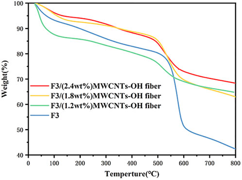
FIGURE 13. TGA of the F3/MWCNTs-OH fibers.
3.8 Electrical performance
This experiment applied the electric bridge method principle, replacing a resistance box with a high-resistance electrometer. The resistance R1 of the F3 fibers was determined to be 5.00 × 10¹⁴ Ω, and the density ρm1 of the short fibers in F3 was 1.45 g/cm3. Subsequently, the fiber-specific resistance ρ1 was calculated using Equation 3, yielding a value of 1.293 × 10¹⁵ Ω cm. For the composite fibers with a 1.2wt% MWCNTs-OH content, the resistance R2 was found to be 3.536 × 10⁹ Ω, and their short fiber density ρm2 was 1.452 g/cm3. Consequently, the fiber-specific resistance ρ2 was calculated as 9.039 × 10⁹ Ω cm. In the case of composite fibers with a 1.8wt% MWCNTs-OH content, their resistance R3 was 2.761 × 10⁹ Ω, short fiber density ρm3 was 1.454 g/cm3, and the fiber-specific resistance ρ1 was computed as 7.121 × 10⁹ Ω cm. Lastly, for composite fibers with a 2.4wt% MWCNTs-OH content, their resistance R4 was 1.293 × 10⁹ Ω, and the short fiber density ρm4 was 1.456 g/cm3. Likewise, the specific resistance ρ4 of the fibers was computed as 3.330 × 10⁹ Ω cm. Employing the electric bridge method for resistance testing of short chemical fibers and the subsequent calculations of specific resistance provided a dependable approach for assessing the conductivity of these fibers. A summary of the test data is presented in Table 2.
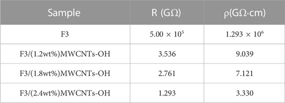
TABLE 2. Antistatic performance of fibers.
As depicted in Figure 14, the modification mechanism of composite fibers involved the application of pressure to the composite spinning solution through the spinning needle (Du et al., 2004). The pressure orientation procedure aligned MWCNTs-OH and established clearly defined conductive routes within the fiber. This transformation enabled F3 fibers, which were initially non-conductive, to manifest antistatic characteristics during the spinning orientation. Through experiments and calculations, it was determined that the inclusion of MWCNTs-OH in F3 established conductive pathways, resulting in successfully modified black aramid fibers with antistatic characteristics.
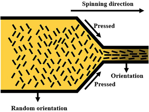
FIGURE 14. Conductivity mechanism of the F3/MWCNTs-OH composite fibers.
4 Conclusion
In this investigation, MWCNTs-OH were effectively distributed within the aramid III spinning solution. Characterization methods were utilized to validate the thorough combination of MWCNTs-OH with F3 macromolecules, resulting in a homogeneous dispersion. Following this, MD simulations were carried out to explore the intricate dispersion mechanism of MWCNTs-OH in the aramid III spinning solution. Wet spinning technology was employed to produce F3/MWCNTs-OH composite fibers. Characterization results indicated that when the MWCNTs-OH content was 2.4wt%, the composite fibers exhibited the best overall performance. In terms of microstructure, at this MWCNTs-OH content, the fiber texture appeared uniform, and the surface morphology promoted adhesion without compromising the overall fiber performance. Regarding mechanical properties, the tensile strength increased significantly, rising from 0.5677 GPa for pure F3 fibers to 1.210 GPa when the MWCNTs-OH content reached 2.4wt%. This noteworthy 113.25% improvement can be attributed to the incorporation of brittle MWCNTs-OH, which enhanced the mechanical properties of the original fibers and eliminated the yield stage. In the domain of thermal characteristics, the composite fibers displayed favorable attributes. The mass reduction in the temperature range of 0°C–538°C was 21.24%, marking a notable 7.72% decrease compared to pure F3 fibers. Between 538°C and 800°C, the mass loss amounted to only 10.31%, a substantial reduction of 71.03% compared to pure F3 fibers. Beyond 800°C, the composite fibers retained 68.45% of their mass, which constituted a 61.17% increase compared to the residual mass of pure F3 fibers. Furthermore, electrical performance testing confirmed that the black composite fibers possessed antistatic properties, with a measured resistance of 1.29336 × 10⁹ Ω and a specific resistance (ρ) of 3.331 × 10⁹ Ω cm. In summary, this study successfully developed a composite fiber material with antistatic properties that combined the excellent mechanical and thermal properties of F3 with the benefits of CNTs. This material exhibits potential applications in military protection to reduce the risks associated with static electricity.
Data availability statement
The original contributions presented in the study are included in the article/Supplementary material, further inquiries can be directed to the corresponding author.
Author contributions
DZ: Conceptualization, Formal Analysis, Methodology, Software, Writing–original draft, Writing–review and editing. WY: Conceptualization, Formal Analysis, Methodology, Writing–review and editing. YN: Formal Analysis, Writing–review and editing. XH: Conceptualization, Methodology, Writing–review and editing. FL: Methodology, Writing–review and editing. HX: Formal Analysis, Writing–review and editing.
Funding
The author(s) declare that no financial support was received for the research, authorship, and/or publication of this article.
Conflict of interest
Author HX was employed by Beijing Trans-universe Space Technology Co., Ltd.
The remaining authors declare that the research was conducted in the absence of any commercial or financial relationships that could be construed as a potential conflict of interest.
Publisher’s note
All claims expressed in this article are solely those of the authors and do not necessarily represent those of their affiliated organizations, or those of the publisher, the editors and the reviewers. Any product that may be evaluated in this article, or claim that may be made by its manufacturer, is not guaranteed or endorsed by the publisher.
References
Cao, K., Jiang, M., Liu, Y., Yang, yiu, Yuan, F., Li, Z., et al. (2020). Preparation and properties of meta-aramid fiber containing imidazole structure. Polym. Mater. Sci. Eng. 36 (11), 69–75.
Du, F., Scogna, R. C., Zhou, W., Brand, S., John, E., and Winey, K. I. (2004). Nanotube networks in polymer Nanocomposites: rheology and electrical conductivity. Macromolecules 37 (24), 9048–9055. doi:10.1021/ma049164g
Duan, H., Wang, S., Hou, C., Ma, G., Li, S., and Xiaogang, H. (2019). Properties of epoxy groups in modifying multiwalled carbon nanotubes and their chemically cross linked polyurethane composites. Funct. Mater. 50 (6), 6155–6161.
Gong, X., Liu, J., Baskaran, S., Voise, R. D., and Young, J. S. (2000). Surfactant-assisted processing of carbon nanotube polymer composites. Chem. Mater. 12, 1049–1052. doi:10.1021/cm9906396
Gürakın, H. K., Turan, A. C., and Deligöz, H. (2019). Synthesis of a novel polyester-ether copolymer and its derivatives as antistatic additives for thermoplastic films. Polym. Test. 81, 106214. doi:10.1016/j.polymertesting.2019.106214
Hao, X. Y., Chien, A.-T., Hua, X. Y., Lu, J., and Liu, Y. D. (2013). Dispersion of pristine CNTs in UHMWPE solution to prepare CNT/UHMWPE composite fibre. Mater. Res. Innovations 17 (1), 123–125. doi:10.1179/1432891713Z.000000000201
Hufenus, R., Gooneie, A., Sebastian, T., Simonetti, P., Geiger, A., Parida, D., et al. (2020). Antistatic fibers for high-visibility workwear: challenges of melt-spinning industrial fibers. Materials 13 (11), 2645. doi:10.3390/ma13112645
Jahangiri, S., and Ozden-Yenigun, E. (2018). The stability and dispersion of carbon nanotube-polymer solutions: a molecular dynamics study. J. Industrial Text. 47 (7), 1568–1583. doi:10.1177/1528083717702006
Li, C., Liang, T., Lu, W., Tang, C., Hu, X., Cao, M., et al. (2004). Improving the antistatic ability of polypropylene fibers by inner antistatic agent filled with carbon nanotubes. Compos. Sci. Technol. 64 (13-14), 2089–2096. doi:10.1016/j.compscitech.2004.03.010
Liang, X., and Cheng, Q. (2018). Synergistic reinforcing effect from graphene and carbon nanotubes. Compos. Commun. 10, 122–128. doi:10.1016/j.coco.2018.09.002
Liao, M., Wang, C., Hong, Y., Zhang, Y. F., Cheng, X. L., Sun, H., et al. (2022). Industrial scale production of fibre batteries by a solution-extrusion method. Nat. Nanotechnol. 17, 372–377. doi:10.1038/s41565-021-01062-4
Liu, Y., Lu, S., Luo, J., Zhao, Y., He, J., Liu, C., et al. (2023). Research progress of antistatic-reinforced polymer materials: a review. Polym. Adv. Technol. 34 (4), 1393–1404. doi:10.1002/pat.5978
Ma, A., and Srpsa, B. (2020). Low temperature growth of carbon nanotubes - a review. Carbon Int. J. Spons. by Am. Carbon Soc. (158), 158. doi:10.1016/j.carbon.2019.11.061
Robert Charles, P., Serra, A., and Bacon David, J. (1999). Dislocations in interfaces in the hcp metals-II. Mechanisms of defect mobility under stress. Acta Mater. 47 (5), 1441–1453. doi:10.1016/s1359-6454(99)00017-8
Stephenson, J. J., Sadana, A. K., Higginbotham, A. L., and Tour, J. M. (2006). Highly functionalized and soluble multiwalled carbon nanotubes by reductive alkylation and arylation:the Billups reaction. Chem. Mater. 18, 4658–4661. doi:10.1021/cm060832h
Wang, W., Wang, Y., and Li, X. (2018). Molecular dynamics study on mechanical properties of cellulose with air/nitrogen diffusion behavior. BioResources 13 (4), 7900–7910. doi:10.15376/biores.13.4.7900-7910
Xu, C., Fang, L., Yu, M., Ren, M., Sun, J., and Zhang, L. (2021). Enhancing anti-static performance of fibers by construction of the hybrid conductive network structure on the fiber surface. Polymers 13 (14), 2248. doi:10.3390/polym13142248
Xu, Z., Wang, J., Zhu, Y., Pang, Z., and Ge, M. (2023). Preparation and properties of light-colored antistatic ATZO@TiO2/PAN fiber. J. Wuhan. Univ. Technol.-Mat. Sci. Ed. 38, 766–770. doi:10.1007/s11595-023-2757-6
Zang, X. (2019). Molecular dynamics simulations of microcrack extension in single crystal and polycrystalline titanium. Changchun, Jilin: Changchun University of Science and Technology.
Zhang, S.-hui, Guo-qiang, He, Liang, G.-zheng, Cui, H., Zhang, W., and Wang, B. (2010). Comparison of F-12 aramid fiber with domestic armid fiber III on surface feature. Appl. Surf. Sci. 256 (7), 2104–2109. doi:10.1016/j.apsusc.2009.09.055
Keywords: aramid III, MWCNTs-OH, antistatic, high-strength, wet spinning
Citation: Zhang D, Yu W, Ni Y, Hao X, Lu F and Xu H (2023) Preparation and properties of antistatic high-strength aramid III/MWCNTs-OH fibers. Front. Mater. 10:1309012. doi: 10.3389/fmats.2023.1309012
Received: 07 October 2023; Accepted: 02 November 2023;
Published: 13 November 2023.
Edited by:
Luca Valentini, University of Perugia, ItalyReviewed by:
Sheraz Ahmad, National Textile University, PakistanSilvia Bittolo Bon, University of Perugia, Italy
Copyright © 2023 Zhang, Yu, Ni, Hao, Lu and Xu. This is an open-access article distributed under the terms of the Creative Commons Attribution License (CC BY). The use, distribution or reproduction in other forums is permitted, provided the original author(s) and the copyright owner(s) are credited and that the original publication in this journal is cited, in accordance with accepted academic practice. No use, distribution or reproduction is permitted which does not comply with these terms.
*Correspondence: Xiangyang Hao, aHh5MTk2OWN1Z2JAMTYzLmNvbQ==