 Zhi Qin1
 Wensheng Wang
94% of researchers rate our articles as excellent or good
Learn more about the work of our research integrity team to safeguard the quality of each article we publish.
Find out more
ORIGINAL RESEARCH article
Front. Mater., 06 December 2023
Sec. Structural Materials
Volume 10 - 2023 | https://doi.org/10.3389/fmats.2023.1301504
The problem of goaf treatment has become more and more prominent, posing a significant risk to the safety of transportation and causing environmental damage if it is not treated properly. This study aims to conduct a comparative analysis of various grouting pastes and evaluate their application in goaf treatment according to grouting backfilling. This research begins by discussing different grouting pastes’ properties, including clay-cement composite grouting material and geopolymer grouting material, which have excellent engineering performance, environmental friendliness, and are easy to operate in complex geological environments. Moreover, the factors affecting the performance of grouting pastes, such as water-solid ratio and curing time, are also examined. Based on detailed information about the boreholes provided by drilling television, a reasonable treatment plan is formulated for goaf treatment. Finally, this study evaluates the effectiveness of different grouting pastes in real-world goaf treatment projects. The study draws the following conclusions: a direct relationship exists among flowability, setting time as well as water-solid ratio. An inverse relationship exists between the compressive strength of grouting materials and the water-solid ratio. Drilling data reveals complex goaf structures with defects such as water leakage, collapse and cavity, indicating potential geological risks in shallow areas. A treatment plan is formulated based on the geological conditions of goafs by drilling television. The effectiveness of backfill grouting in goaf areas is inspected using ground-penetrating radar (GPR) technology, and results indicate that adjusting water-solid ratio of grouting material can improve treatment effects.
Mining activities can lead to the formation of goafs, which are large underground cavities that are left behind after coal mining. However, with the expansion of mining activities, goaf treatment problem has been more and more popular (Song et al., 2020; Liu et al., 2022). The goafs pose a significant risk to the safety of mining operations and transportation, and can also cause environmental damage, if it is not treated properly (Wang et al., 2019; Marian et al., 2020; Han et al., 2022). Thus, it is imperative to devise a viable approach for goaf treatment in order to guarantee the sustainable progress of the transportation infrastructure.
In recent years, due to speedy advancement of China’s expressway construction, some highways have encountered secondary geological hazards caused by coal mining subsidence to varying degrees. Some road scholars have also begun to explore impact of goafs. The investigation of goaf areas beneath highways has garnered significant attention from both domestic and international scholars, who have conducted numerous studies on the damage caused by underground cavities, including goafs, to highway infrastructure (Guo et al., 2019; Guo et al., 2021). Cao et al. conducted a study about goaf detection in mines, highlighting significance for precise reconnaissance ways as well as utilization of prior technologies like seismic reconnaissance etc. to identify potential mined-out regions. (Cao et al., 2022). The investigation also presents utilization of laser examining technology for visualizing concealed mined-out regions and analyzing the corresponding formation mechanisms. Zhang et al. studied stress analysis for the central region in goaf roof. They concluded structural parameter of the mining stope is justifiable, faults would induce subsidence (Zhang et al., 2019). Accurate detection methods for abandoned goafs are necessary to assess the building stability, a combination of step-by-step, traditional, and seismic methods were used to identify a desolate goaf within the Mu Shi expressway of China (Zhang et al., 2022). Han et al. conducted an analysis of the stability and methods for excavating and reinforcing for a side slope of cut with goaf roadway of falling in. They determined fallen side is a primary part influencing steadiness as well as proposed particular ramp percentages for digging and reinforcement ways (Han et al., 2022). Generally, the construction of expressways in goaf areas is still a relatively new field, and there is currently a lack of established governance theories and technologies. This area is still being explored and developed.
Once the coal seams have been extracted, goaf areas are often abandoned, leading to a disruption of the original equilibrium conditions within the forming of rock structures and the development of secondary stress (Li et al., 2022; Zhou et al., 2022). Once the stress reaches a crucial value for ambient rock, goaf area would deform as well as crash, causing top fracturing, overlying stratum collapsing etc., which not only threatens life and property safety but also results in a waste of land resources. For road engineering, uneven settlement of embankments can cause cracking of the overlying roadbed and pavement structures.
Currently, the optimal approach for mitigating goaf regions is through reinforcing ways (Hebblewhite and Lu, 2004; Yu et al., 2020). Grouting reinforcing way is a frequently employed remedial manner for goaf regions in both domestic and international highway contexts (Zhang and Shimada, 2018; Dun et al., 2022; Li et al., 2022). Grouting reinforcing method entails the high-pressure injection of a specifically formulated slurry material into the rock as well as soil within the goaf region, employing corresponding equipment. The slurry exhibits initial fluidity upon configuration. Upon reaching the gaps, fracture within rock as well as soil, it progressively undergoes solidification and hardening, resulting in the formation of a robust consolidation structure. These consolidation bodies adhere to the primitive rock as well as soil to form all in one, achieving a purpose of improving the bearing capacity and impermeability of the rock and soil and controlling its deformation. Wang et al. introduced an enhanced pure theoretically equation for the process of seeping in goaf base, incorporating the break classification features and the superposition effect of absorbent slip casting. The validity of this formulation was confirmed via laboratory experiments, underscoring its crucial role in optimizing the spacing between slip casting holes. This optimization aims to minimize residual as well as activation distortion of base at goaf locations, carrying substantial engineering implications (Wang et al., 2022).
However, the effectiveness of grouting largely depends on the properties of the grouting paste used. For grouting reinforcement projects, the filling paste selection is a very essential issue, influencing consolidation cause and cost for grouting projects (Huang et al., 2022). Extensive research has been conducted by researchers both domestically and internationally on slip casting materials, with particular emphasis on cement-clay mud, single-cement mud, cementitious mud, some similar substances (Feng et al., 2022). Utilizing traditional slip casting materials for goaf regions filling presents challenges in terms of mud accumulation, leading to substantial mud loss and reduced stone formation rate. This ultimately contributes to a significant increase in treatment costs. Compared with traditional grouting materials, clay-cement composite grouting material and geopolymer grouting material have the characteristics of lightweight, high strength, good seismic performance, environmental protection, and resource conservation (Lim et al., 2013; Shi et al., 2020; Shaheen et al., 2023). There are some recent papers about the geopolymer, which is more suitable for highly corrosive applications such as marine engineering and chemical factories due to its high strength and corrosion resistance (Yang et al., 2021; Yang et al., 2022; Yang et al., 2023). Some studies used industrial solid wastes circulating fluidized bed fly ash, calcium carbide slag, volcanic ash, metakaolin and flue gas desulfurized gypsum as the main raw materials to prepare eco-friendly geopolymer grouting materials (Zhou et al., 2021; Duan et al., 2023). Grouting materials have gained extensive usage in the domain of civil engineering owing to their exceptional attributes, encompassing elevated strength, diminished thermal conductivity, and commendable workability (Kadela et al., 2020; Song and Lange, 2021; Allouzi et al., 2023). Recently, scholars have initiated the application of the slip casting material in the realm of goaf treatment. Compared with conventional goaf treatment ways, examples of these practices include backfilling using solid materials or filling techniques employing water, clay-cement composite grouting material and geopolymer grouting material have many advantages. For example, the material is conveniently inserted to gap via piping, effectively occupying goaf cavity as well as significantly mitigating the potential for surface subsidence resulting from goaf collapse (Xu et al., 2020; Shrestha et al., 2022). Wang et al. proposed a new method of using coal gangue powder as the dominant component in grouting backfill materials for underground mining with optimized slurry transportability and compressive strength using urea and quicklime as additives (Wang et al., 2023). Yuan et al. used molecular dynamics simulations for relationship between crosslinking degree as well as properties for polyurethane grouting materials, providing insights into their microstructure and thermomechanical properties (Yuan et al., 2022). In sum, the clay-cement grouting paste has good durability and strength, while geological polymer grouting paste has higher strength and corrosion resistance, and both have good cost-effectiveness. Therefore, it is recommended to use the clay-cement grouting paste and geopolymer grouting paste for comparison.
The main aim of this study is to determine whether two kinds of grouting pastes could be used for goaf treatment. The paper begins with a discussion about the properties of different grouting pastes, including clay-cement composite slip casting material as well as geological polymeric slip casting composition. The factors that affect the performance of grouting pastes are also examined, like water-solid ratio as well as curing time. Besides, based on the detailed information about the boreholes by drilling television, a reasonable treatment plan is formulated for goaf treatment. Then, the grouting effect of different grouting pastes is evaluated based on the application in actual goaf treatment projects. In this study, a comparative analysis of various grouting pastes is discussed and their application on the grouting effect of goaf treatment is also evaluated based on the grouting backfilling method. The presented research is of a pilot nature as an indication of a potential treatment way of goaf areas beneath highways.
The primary raw materials for preparing clay-cement composite grouting material included cement, bentonite, and water. Cement was the main cementitious material of clay-cement composite grouting material, which provided the intensity for clay-cement composite after the hydration and hardening reaction. In order to guard that the intensity of clay-cement composite slip casting material can meet actual needs of the project, the clay-cement composite grouting material usually requires higher quality of cement. The ordinary Portland cement (P.O 42.5) has the characteristics of elevated initial intensity, rapid setting duration and enhanced density, rendering it efficacious as a cementitious substance. Therefore, Runfeng 42.5# cement was chosen as one of the raw materials for this experimental study, and its performance in Table 1 should meet the demands of Chinese specification (GB 175-2007). And Figure 1 shows the chemical composition results of the XRF analysis.

TABLE 1. Basic properties of cement.
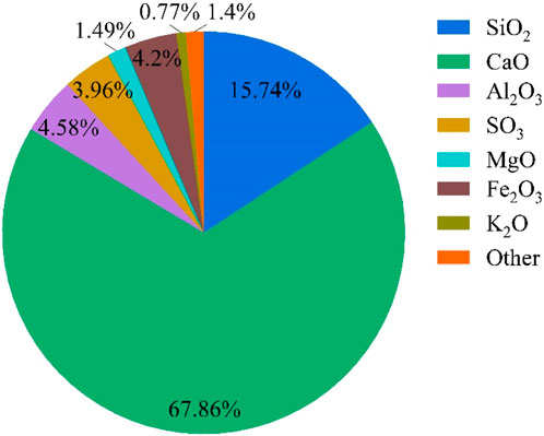
FIGURE 1. Chemical composition of cement determined via XRF.
Bentonite is a non-metallic mineral with montmorillonite as the main mineral component, which has obvious characteristics of high viscosity, water absorption and expansion. Bentonite was a necessary material of clay-cement composite grouting material, and its performance index would directly affect various performances for clay-cement grouting composite. Bentonite plays its high viscosity and cementitious characteristics in the clay-cement composite grouting material. By controlling the amount of bentonite, the fluidity of clay-cement composite grouting material can be adjusted and the diffusion range can be controlled, determined as 20%. The basic performances of bentonite in this study are listed in Table 2. Water was also an important raw material of the clay-cement composite grouting material, and the water quality and consumption would have the direct influence on its properties. The blending water should not contain impurities such as oil or organic matter to prevent affecting the properties of the clay-cement composite grouting material. If there are too many impurities in the blending water, when mixing with cement, the adverse impurity in water will corrode into cementitious glue, thus affecting its performances for clay-cement composite for slip casting. The water consumption has an influence on physical as well as mechanical performances and durability of clay-cement composite for slip casting. Therefore, in order to ensure the level of clay-cement composite for slip casting, the water mass as well as consumption should be strictly controlled during the preparation process of the clay-cement composite grouting material.

TABLE 2. Basic properties of bentonite in this study.
In addition, the geopolymer grouting material was also adopted for goaf treatment. Based on various solid waste collaborative configuration experiments, an environmentally friendly new type of geopolymer grouting material was developed in this study. The geopolymer paste used slag and fly ash as raw materials, and sodium silicate and sodium hydroxide are combined as alkali activators to prepare slag based geopolymer paste. The promotion of fly ash and lag of the solid materials is 2:3, NaOH was analytically pure, and SiO2 29.7% (wt) and Na2O 9.8% (wt) in sodium silicate solution. Using aluminum silicate mineral slag, high-quality fly ash and other raw materials rich in silicon and aluminum with potential volcanic ash characteristics, stimulated by alkaline substances, a highly flowable and durable geopolymer grouting material was prepared through the development of composite alkali activators and application of limestone powder with content of 5% to regulate rheological and shrinkage properties. Therefore, for two types of grouting pastes, the water-solid ratio of clay-cement grouting material was determined as 0.35, 0.40 and 0.45; while the water-solid ratios of geopolymer grouting material was 0.50, 0.60 and 0.70 with bentonite content of 20%.
In this study, two kinds of grouting materials were prepared for the goaf treatment. The clay-cement composite grouting material and geopolymer grouting material had similar preparation procedure, and the intricate process of preparation of clay-cement composite and geopolymer for slip casting is descripted as listed below:
Step 1: In accordance with the composite portion, raw materials included the cementitious material such as cement and geopolymer powder, as well as water, bentonite, etc., subsequently, the aforementioned components were introduced into the mixer for thorough amalgamation;
Step 2: After the mixture was stirred evenly, the prepared clay-cement composite and geopolymer grouting pastes were deposited within the mold to undergo manual vibration as well as molding. Following the demolding process, the mold was subjected to a standardized curing procedure until it reached the designated curing age. Subsequently, a series of performance tests were conducted as per protocol.
The primary instrument for clay-cement composite and geopolymer for slip casting was mixer machine. By controlling the water-solid ratio, the performances were compared and analyzed on these two grouting materials. The production flow for slip casting is plotted in Figure 2.
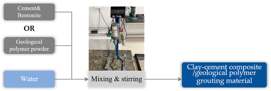
FIGURE 2. Production for slip casting including clay-cement composite grouting material and geopolymer grouting material.
In this study, the basic physical properties of clay-cement composite and geopolymer grouting pastes were measured, including flowability, setting time, flexural strength, and compressive strength. Referring to Standards Press of China (2011), China Water Power Press (2014), the flowability of grouting pastes can be tested by using a Marsh funnel viscosimeter, and the primary testing stages were: funnel mouth was blocked using a finger, and at the same time, the prepared paste was stirred and injected into the funnel calibration line through the sieve on the funnel. The funnel was held vertically in mid-air, the paste would flow into a pre-prepared measuring cup after releasing the finger. When the grouting paste just filled the measuring cup, the time can be recorded as the flowability. Referring to “Test methods for water requirement of normal consistency, setting time and soundness of the portland cement” (GB/T 1346-2011) (2011), the setting time of grouting pastes can be tested. In addition, as an important parameter for evaluating the performance of slip casting paste, the compressive as well as flexural intensity of stone body for pastes was directly related to reinforcement effectiveness in goaf, and the intensities for clay-cement composite as well as geopolymer for slip casting paste can be tested by universal testing machine.
Injectability of indoor grouting slurry utilized the Kima permeameter, i.e., a polyethylene plastic pipe that stands 50 cm tall, boasts an outer diameter of 9 cm, and possesses an inner diameter of 8.5 cm. The operational steps involved connecting the plastic pipes, utilizing tape to secure the joints, fastening the pipe walls with clips to prevent slurry leakage, sealing the base of the plastic pipe with a plastic plate, filling the pipe with sand of the required particle size to a height of approximately 40 cm. Then inject 200 mL of slurry into the pipe’s center, allowing it to spread naturally, gauging fluidity before injection, placing the sample indoors for 3 days. Note that remove the mold during the process while avoiding severe vibrations and preventing sample breakage, and using a ruler to measure the consolidated body’s longitudinal length for characterizing the injectability of various slurries.
Ground-penetrating radar (GPR) is a technology that emits high-frequency electromagnetic waves to detect targets underground via an emitting antenna. During the propagation of electromagnetic waves in a medium, phenomena such as refraction and transmission occur when encountering interfaces with large differences in electrical properties. The received signal is then picked up by a receiving antenna and transmitted back to the GPR main unit. This principle is similar to seismic reflection, as shown in Figure 2. By analyzing the waveform, intensity, travel time, and other characteristics of the received electromagnetic wave signal, the location, structure, and shape of geological features can be determined.
The equation for electromagnetic wave reflection coefficient (R) is as follows:
in which,
The distance (L) of the target detected by GPR can be calculated using the Eq. 2:
in which, v is propagation speed of electromagnetic waves in medium; t is round-trip duration of electromagnetic wave.
The depth (h) of the reflecting interface can be calculated using the Eq. 3:
in which, x is the distance separating the transmitting antenna from the receiving antenna.
The velocity of electromagnetic waves in a medium can be determined using the Eq. 4:
in which, c is the speed of electromagnetic waves in a vacuum (c = 3 × 10⁸ m/s); ε′ is the relative permittivity of the medium through which the electromagnetic waves are propagating.
Flowability is an important performance that needs to be considered during the construction for slip casting in the goaf. Flowability of paste for slip casting directly affects the pumpability during on-site grouting of goaf, and determines the effectiveness and quality of the grouting material when injected on-site. So it is imperative to investigate effects of various water-solid ratios on their flowability for two types of grouting materials (i.e., clay-cement composite grouting material and geopolymer grouting material). Figure 3 shows the experimental results of the flowability of the grouting material pastes under different water-solid ratio variables of the clay-cement composite grouting material and geopolymer grouting material. As can be seen from Figure 3, there is an inverse relationship between the flowability of the clay-cement composite and geopolymer for slip casting as well as water-solid ratio. For geopolymer grouting material, when water-solid ratio is changed starting 0.35 to 0.40, flowability decreases from 30.16 s to 11.09 s, a significant decrease of 19.07 s. However, while water-solid ratio is raised starting 0.40 to 0.45, flowability for geopolymer grouting material decreases from 11.09 s to 9.06 s, a decrease of only 2.03 s, which is much lower than the decrease observed while water-solid ratio is raised starting 0.35 to 0.40. For clay-cement composite grouting material, while water-solid ratio is starting 0.50 to 0.60, flowability decreases significantly from 23.61 s to 13.35 s. However, while water-solid ratio is further raised starting 0.60 to 0.70, flowability for cement-bentonite grouting material decreased from 13.35 s to 6.47 s, which is also much lower than the decrease observed while water-solid ratio is starting 0.50 to 0.60. For geopolymer grouting material and clay-cement composite grouting material, the rate of increase in flowability varies with the water-solid ratio, increasing at first and then decreasing. A higher level of flowability indicates overly diluted material, and adding more water will not significantly develop its flow performances for grouting paste.
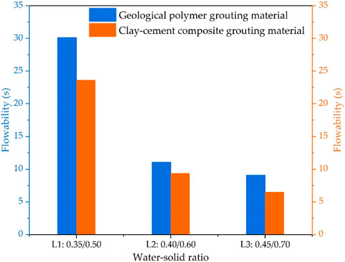
FIGURE 3. The flowability of two kinds of grouting material pastes under different water-solid ratio variables.
The setting time of paste for slip casting is the time it takes for paste to go from mixed to losing its fluidity. Setting time is a valuable indicator for assessing the paste quality, and controllable setting time is often required in actual engineering. The length of the setting time affects the size of the grouting radius. When it is necessary to expand the diffusion radius or the grouting radius, the setting time needs to be extended to allow it to flow sufficiently. When groundwater exists, it is necessary to effectively shorten the setting time so that the paste can quickly set to prevent being washed away and ensure the grouting effect. The control of the setting time is particularly strict, and it should be ensured that the paste is not diluted or washed away by groundwater under the premise of full injection of the paste. The final setting time determines whether the paste can effectively prevent seepage and blockage, and also determines the effect of reinforcing the engineering body. Controlling final setting time can maintain its fluidity for a longer period of time during the initial injection stage, which is beneficial for the paste to diffuse in the cracks. After the paste enters the target area, it can quickly solidify in a brief time frame to meet requirements for engineering slip casting. So it is imperative to investigate the effects of different variables on fluidity. Figure 4 displays the setting time values for two kinds of grouting material pastes under different water-solid ratios. As shown in Figure 4, there is a direct relationship between the setting time of clay-cement composite and geopolymer for slip casting and water-solid ratio, as water-solid ratio increases, both final setting time of these two kinds of grouting material also increases. Clay-cement composite and geopolymer for slip casting are common materials used for underground engineering leakage plugging such as goaf. The setting time test results at different water-solid ratios can provide reference for material performance.
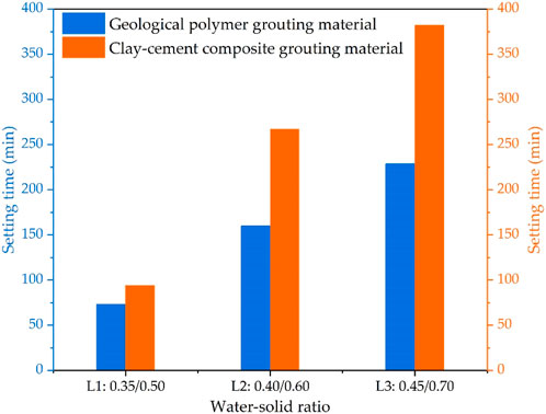
FIGURE 4. The setting time of two kinds of grouting material paste under different water-solid ratio variables.
The mechanical properties of grouting composition are one of the important indicators of their performance evaluation. Mechanical performance reflects the load-supporting capability as well as resistance to distortion and damage for grouting material itself. This study mainly tests the compressive strength of geopolymer paste and clay-cement composite paste under various water-solid ratios on specimens cured for 3 d, 7 d, 28 d. The compressive experimental results for two kinds paste under water-solid ratios and curing ages are shown in Figure 5, respectively.
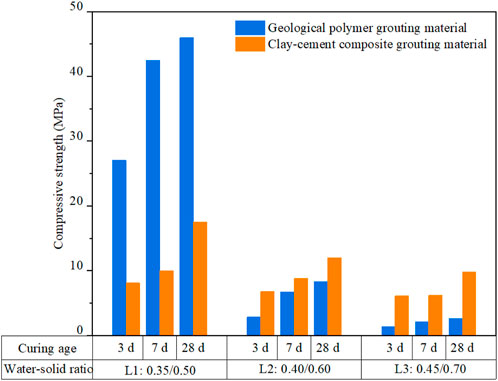
FIGURE 5. The compressive strength test results of the geopolymer grouting material and clay-cement composite grouting material.
From Figure 5, for the geopolymer grouting material, at a water-solid ratio of 0.45, the compressive strength of the 3-d curing age grouting material specimens is the smallest, only 1.40 MPa, while compressive strength at water-solid ratio of 0.35, 28 d is the largest, reaching 46.00 MPa. Under the same water-solid ratio conditions, there is a proportional connection between compressive strength for geopolymer paste as well as curing age. Under the same curing age conditions, there is an inverse connection between compressive strength for geopolymer paste as well as water-solid ratio. As water-solid ratio increases, compressive strength of geopolymer grouting materials also decreases. When a water-solid ratio is 0.35, compressive strength for geopolymer grouting material reaches to 27.08 MPa at 3 d, much larger than the geopolymer grouting material specimens at the ratios of water to solid of 0.40 as well as 0.45. The compressive strength of geopolymer pastes with water-solid ratio of 0.45 varies slightly with increasing curing time, and there is almost no change. Meanwhile, compared to the compressive strength at water-solid ratio of 0.40, compressive strength for geopolymer grouting material at a water-solid ratio of 0.45 also decreases, but the reduction amplitude is smaller compared to that at a water-solid ratio starting 0.35 to 0.40. This indicates that mechanical properties of the geopolymer grouting material are greatly influenced by the water-solid ratio under the same curing age conditions. For clay-cement composition for slip casting in Figure 5, at a ratio of water to solid of 0.70, 3-d compressive strength is the smallest, while 28-d compressive strength is the largest. Under the same water-solid ratio conditions, there is also a proportional relationship between compressive strength for clay-cement composite grouting material and the curing age. Under the same curing age conditions, there is an inverse relation between compressive strength for clay-cement composite material and water-solid ratio. As water-solid ratio increases, compressive strength for clay-cement composite grouting material also decreases. Besides, at a ratio of water to solid of 0.70, compressive strength for clay-cement composite grouting material also decreases, but the reduction amplitude is smaller compared to that at a ratio of 0.60.
In summary, compressive strength results for two grouting materials at various water-solid ratios and curing age are different. Compressive strength of clay-cement composite and geopolymer for slip casting is influenced by multiple factors, including the water-solid ratio and curing age. While compressive strength for geopolymer grouting material is primarily affected by water-solid ratio. These compressive strength results could also suggest that appropriate grouting materials should be chosen according to actual situations and reasonable curing is also paid attention to during construction to achieve better results.
Clay-cement composite grouting material and geopolymer grouting material are two common types of grouting materials used in civil engineering for soil stabilization and foundation reinforcement. In this study, the flexural strength of geopolymer grouting material and clay-cement composite grouting material are tested under different water-solid ratios on specimens cured for 3 d, 7 d, 28 d. Experimental results of the flexural strength for two kinds of grouting materials under different water-solid ratios and curing ages are plotted in Figure 6, respectively, to report load-bearing capacity and resistance to deformation and damage.
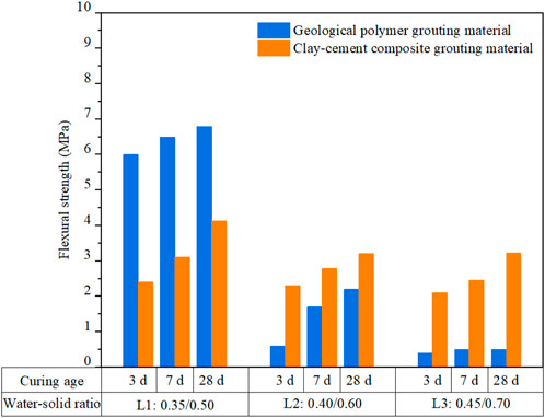
FIGURE 6. The flexural strength test results of the geopolymer grouting material and clay-cement composite grouting material.
From Figure 6, for the geopolymer grouting material, at a ratio of water to solid of 0.45, flexural strength of 3-d curing age grouting material specimens is the smallest, only 0.40 MPa, while the value of 28-d specimens at water-solid ratio of 0.35 is the largest, reaching 6.80 MPa. Under the same water-solid ratio conditions, there is a proportional relation between flexural strength of geopolymer grouting materials and curing age. Under the same curing age conditions, there is an inverse relation between flexural strength of geopolymer grouting materials and water-solid ratio. As water-solid ratio enlarges, flexural intensity of geopolymer grouting materials also decreases. When water-solid ratio is 0.35, compressive strength for geopolymer grouting material reaches to 6.00 MPa at 3 d, which is much larger than the geopolymer grouting material specimens at water-solid ratios of 0.40 and 0.45. Although flexural intensity for geopolymer grouting material at water-solid ratio of 0.45 also decreases compared to the compressive strength at a ratio of water to solid of 0.40, flexural strength at a ratio of 0.45 varies slightly with increasing curing age, and there is almost no change, in which the variation amplitude is smaller compared to that at a water-solid ratio starting 0.35 to 0.40. This indicates that the mechanical properties of geopolymer grouting material are greatly influenced by water-solid ratio under same curing conditions. The clay-cement composite grouting material has the similar variation trend of the flexural strength with the geopolymer grouting material. At a ratio of water to solid of 0.70, 3-d flexural intensity is the smallest, while 28-d flexural intensity is the largest at a ratio of water to solid of 0.50. Under the same water-solid ratio conditions, there is also a proportional relationship between flexural strength of clay-cement composite grouting material and the curing age. Under the same curing age conditions, there is an inverse relation between the flexural strength of clay-cement composite grouting material and water-solid ratio. As water-solid ratio enlarges, flexural strength of clay-cement composite grouting material also decreases. Flexural strength results for above two materials for slip casting under different water-solid ratios and curing age are different. Flexural strength of geopolymer and clay-cement composite grouting material is influenced by multiple factors, including the water-solid ratio and curing age, in which the flexural strength of geopolymer composition for slip casting is significantly affected by water-solid ratio.
By comparison of the above mechanical performance including compressive as well as flexural strength, their difference between geopolymer grouting material and clay-cement composite grouting material lies in their composition and properties. Geopolymer grouting material is a type of inorganic polymer material that is formed by chemically activating aluminosilicate minerals or industrial wastes with alkaline solutions. It has a high early strength and good durability, and can be hardened even under water. However, its workability is relatively poor, which may limit the construction efficiency. Clay-cement composite grouting material, on the other hand, is a mixture of Portland cement, bentonite, as well as water. It has a lower early intensity compared to geopolymer grouting material, but it has better workability and can be easily pumped to the site of application. It also has good sealing properties due to the swelling property of bentonite. In terms of water-solid ratio, geopolymer grouting material usually requires a lower ratio than clay-cement composite grouting material to achieve the same level of strength. This is because the chemical reaction involved in geopolymerization consumes less water compared to cement hydration. Therefore, the geopolymer grouting material can achieve a higher early strength with a lower water-solid ratio. Therefore, both geopolymer grouting material and clay-cement composite grouting materials have their own advantages and disadvantages depending on the specific application scenarios.
The injectability test of indoor grouting slurry was conducted on both geopolymer grouting material and clay-cement composite grouting material in sand with particle sizes of 2–5 mm and 5–10 mm, respectively. The water-solid ratio using geopolymer and water as the base material for the paste was 0.35 for the geopolymer grouting material, while the paste was made up of cement, bentonite, and water, with a ratio of water to solid of 0.6 for paste as well as a bentonite content of 20% by weight of cement for the clay-cement composite grouting material.
Figure 7 shows the consolidated bodies formed by two sets of grouting materials in sand. The geological polymer grouting material had an injection depth of 78 mm in sands with particle size of 2–5 mm. There was a small amount of slurry remaining in the upper part of the device, but it was not injected into the sand. The adhesion of the lower part of the consolidated body was poor, and some sand detachment occurred during the mold removal process. This may be mainly due to the phenomenon of water precipitation in the lower part of the slurry, where only water entered the gaps between the sand and gravel, while most geological polymer particles accumulated at the gaps and caused blockage. The length of the part with good bonding effect in the consolidated body was 52 mm. For the clay-cement composite grouting material, the corresponding maximum injection depth was 86 mm. There was only a small amount of slurry remaining in the upper part of the device, but due to severe water separation, the bonding of the lower consolidated body was poor. The length of the stone body with good solidification effect was 46 mm. However, these two kinds of grouting materials were injected into sands with particle size of 5–10 mm. The geological polymer grouting material had an injection depth of 170 mm. There was no remaining slurry on the upper part of the device, and all was injected into the sand. The bonding between the consolidated body and the sand was good, and a small amount of sand fell off during the mold removal process. The length of the part with better bonding effect was 132 mm. For the clay-cement composite grouting material, there was no slurry residue on the upper part of the device, and the injection depth was 176 mm. The lower part of the consolidation body experienced detachment during demolding, and the length of the part with good bonding effect of the consolidation body was 125 mm.
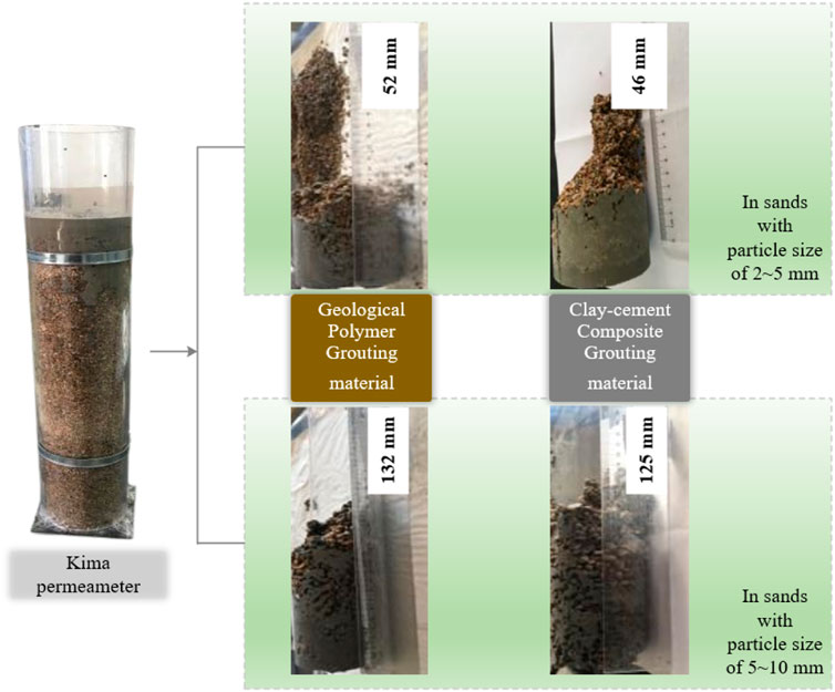
FIGURE 7. The consolidated bodies formed by two sets of grouting materials in sand.
The grouting backfilling method is adopted to treat a goaf below. Twelve drill holes are arranged on both sides of the axis at 0.5 m–1.0 m intervals, and appropriate adjustments are made according to the site conditions and drilling conditions. The layout is shown in Figure 8. The drill holes are required to be positioned according to the design, with a diameter of 110 mm. The drilling should be kept vertical, and the deviation should not exceed 2% of the hole depth. Polyvinyl chloride (PVC) sleeves should be used to protect the walls during drilling. The record and description of drilling should be done well. If special circumstances are found, the conditions should be recorded and analyzed in detail for proper handling.
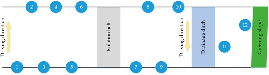
FIGURE 8. The drilling layout of goaf based on grouting backfilling method.
According to the drilling layout shown in Figure 8, rotary drilling was carried out using a geological drilling rig with a hole diameter of 110 mm. The 12 boreholes were completed in 2 days. By combining drilling television, detailed information about the boreholes can be obtained. The color drilling television system involves placing a waterproof camera probe with its own light source into the borehole, enabling real-time observation, monitoring and recording of various features and subtle changes of geological formations within the borehole. This allows for the observation of strata lithology, rock structure, fracture development and characteristics inside the borehole, as well as the filling status of grout and underground water level changes after grouting. Figure 9 shows the on-site drilling situation using the geological drilling rig and drilling television. By combining drilling television with drill core, a detailed analysis of the goaf drilling situation is provided as follows, which is listed in Table 3. For drill hole No. 1, the depth range is from 0 to 7.5 m. At the shallow depths, from 0 to 0.5 m, cement stabilized base exists, followed by a layer of mudstone from 0.5 to 4.0 m. Between 4.4 and 4.7 m, there is a water leakage with a 30 cm cavity, and the same phenomenon occurs between 6.1 and 6.6 m, but with a 50 cm cavity. From 4.7 to 6.0 m, mudstone and coal seams are found, while from 6.6 to 7.5 m, silt layers, coal seams and mudstones exist. There is a suspected underground tunnel at 7.5 m deep. The detailed geological conditions of drill hole No. 2 are similar to that of No. 1. For drill hole No. 2, the depth range is from 0 to 8.7 m. Similarly, there is a cement stabilized base from 0 to 0.5 m, followed by a layer of mudstone from 0.5 to 4.0 m. Between 4.4 and 4.7 m, there is a water leakage with a 30 cm cavity, and between 6.5 and 6.6 m, there is also a water leakage with a 10 cm cavity. From 4.7 to 6.5 m, mudstone and coal cinder are found. Between 6.6 and 7.2 m, there is a loose layer of coal seams and mudstone, followed by another layer of loose sedimentary material from 7.2 to 8.7 m. At 8.4–8.7 m, there is a water leakage with a 30 cm cavity, and a small amount of wood block appears, which is also suspected to be an underground tunnel. For drill hole No. 3, the depth range is from 0 to 10.0 m. The first layer is a cement stabilized base from 0 to 0.5 m, followed by a layer of silt and mudstone from 0.5 to 3.7 m. From 3.7 to 7.0 m, there are mudstones and coal cinder, and a water leakage occurs at 3.7 and 7.0 m. From 7.0 to 8.0 m, there are sedimentary layers, coal seams, and mudstones, followed by a loose layer of coal seams, mudstones, and sedimentary material from 8.0 to 10.0 m deep. For drill holes No. 4 and No. 11, the depth range is from 0 to 7.0 m. There are layers of loose sedimentary materials, mudstones, and coal cinder from 0.5 to 7.0 m. For drill hole No. 5, the depth range is from 0 to 8.0 m. From 0.5 to 5.6 m, there are mudstones and coal cinder, and between 5.6 and 5.8 m, there is a water leakage with a 30 cm cavity. From 5.8 to 8.0 m, there are coal seams and mudstones. For drill holes No. 6, No. 7, No. 8 and No. 12, the depth range is from 0 to 7.0 m, where there are mudstones and coal cinder. For drill holes No. 9 and No. 10, the depth range is from 0 to 7.0 m. From 0.5 to 6.0 m, there are mudstones, and a water leakage occurs at around 4.5 m. From 6.0 to 8.0 m, there are silt layers, mudstones, and coal cinder. A collapse occurs at around 4.0 m deep. In summary, these drilling data show that the goaf structure is complex, and geological risks may exist in shallow areas. It is important to formulate a reasonable treatment plan, monitor the environment closely.
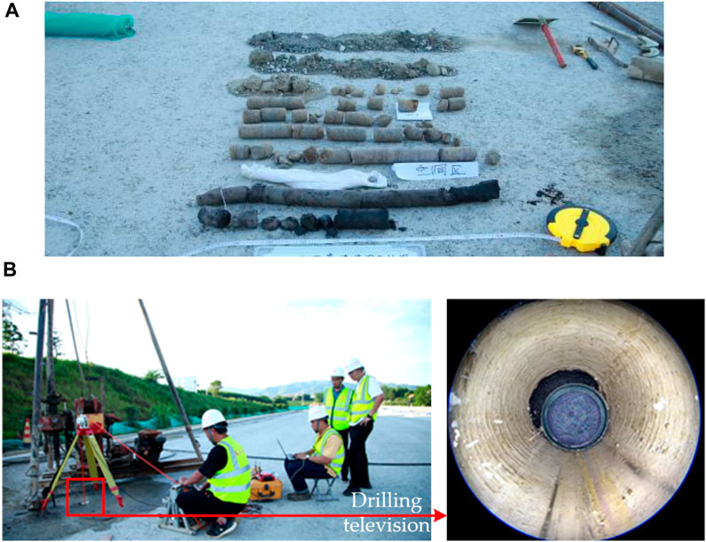
FIGURE 9. The on-site drilling situation using the geological drilling rig and drilling television: (A) Drill core; (B) In-hole situation.
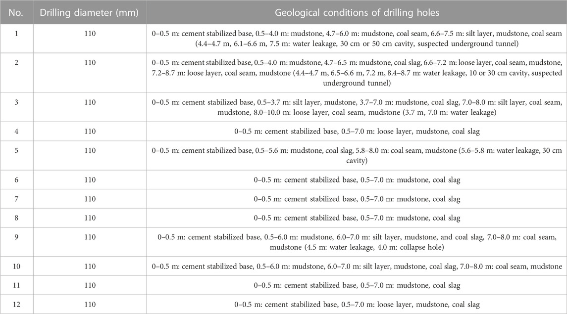
TABLE 3. The detailed analysis of the goaf drilling situation.
This study used ordinary Portland cement, bentonite, and geopolymer as grouting materials in the management and treatment of goaf, and filled the mixture of crushed stone and sand during grouting. Two types of raw material pastes were used for grouting: one was a paste composed of cement, bentonite, and water, the other was a paste composed of geopolymer and water. According to the performance results in Section 3.1, for the geopolymer grouting material, the water-solid ratio using geopolymer and water as the base material for the paste was 0.35. For the clay-cement composite grouting material, the paste was made up of cement, bentonite, and water, with a ratio of water to solid of 0.6 for paste as well as a bentonite content of 20% by weight of cement. For ordinary Portland cement, the cement with a grade of ordinary Portland cement (P.O 42.5) was used, and the quality of the cement should meet the prescribed quality standards. To maintain the freshness of the cement used for grouting, dampened, caked, or expired 3-month factory period cement should not be used. As an admixture, prepared bentonite powder should be added, along with 10–20 mm crushed stone and medium sand. The water used for grouting must meet standard requirements, and the mixing water temperature should not exceed 40°C. The infusion flow rate of the infill material in the goaf is 5,000 kg/h, with an infusion pressure of 1.0 MPa. Geopolymer grouting material was infused into drill holes No. 1, 3, 5, 7, 9, and 11, while clay-cement composite grouting material was infused into drill holes No. 2, 4, 6, 8, 10, and 12. The raw materials were then mixed and stirred into a paste using a mixer, and large particles and impurities were removed through filtration screens and precipitation. All indicators must be controlled according to the design requirements, and the paste volume during the grouting process should be measured and recorded once per hour. If there are changes in the paste, adjustments must be made promptly. The specific process for grouting treatment of goaf is shown in Figure 10 and described as follows:
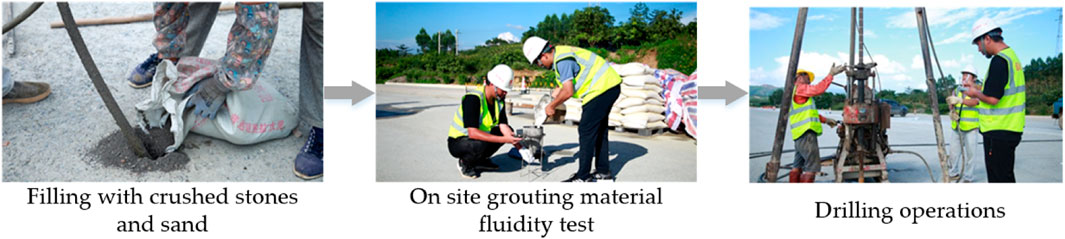
FIGURE 10. The specific process for grouting treatment of goaf.
Step 1. Inject geopolymer grouting material into drill holes 1, 3, 5, 7, 9, and 11 sequentially, and use clay-cement composite grouting material for drill holes 2, 4, 6, 8, 10, and 12. Adjust slurry volume and grouting pressure based on site conditions. If hole pressure drops and negative pressure appears in grouting pipe, increase slurry viscosity immediately.
Step 2. When grouting reaches the endpoint, immediately close the return pipe valve and the inlet pipe valve, so that the injected slurry remains under pressure for a certain period of time. Generally, the closure time is 2–3 h. After setting, open the valve and check if there is still water flowing out. If there is no water flow phenomenon, consider it qualified.
Step 3. Fill the underground tunnel with crushed stones and machine-made sand according to the natural rest angle of the sand and gravel aggregate and the length of the underground tunnel to be filled. When filling the borehole, first fill it with crushed stones, then fill it with machine-made sand.
Step 4. Comprehensively control the grouting volume, grouting pressure, lateral horizontal displacement, and crack opening width throughout the grouting process. The sealing grouting is carried out according to the principle of less grouting and more repetition.
Step 5. Generally, when the injection rate of the grouting segment is not greater than 1 L/min under the maximum design pressure, close the return pipe valve and the inlet pipe valve so that the injected slurry remains under pressure for a certain period of time. After completing the grouting hole, use the whole-hole grouting method for hole sealing.
Based on GPR technology, this study conducted inspections on the effectiveness of backfill grouting in goaf areas. Before grouting, according to the exploration results, the radar image at the measuring line is displayed in Figure 11. The radar signal is stronger at a depth of about 4 m along the measuring line, with obvious multiple reflections, which is consistent with the characteristics of the cavity radar waveform diagram. Through borehole verification, it was confirmed that there is a cavity zone at that location.
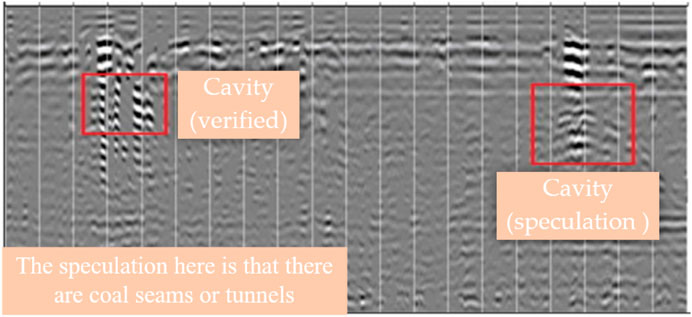
FIGURE 11. The radar image at the measuring line before grouting.
After grouting for 14 days, geological radar was used to detect the filling effect of the grout injection. The specific results of the radar detection around different drill holes in left lane, right lane and side road can be seen in Figure 12. According to the radar images of drill holes 1 and 6 on the left lane in Figure 12A, near drill hole 1, the radar reflection signals at a depth of 2–5 m are mainly uniform low to mid frequencies, with continuous in-phase axes and strong amplitudes. Near drill hole 6, at a depth of 2–4 m, the radar reflection signals are mainly uniform low to mid frequencies, with continuous in-phase axes and strong amplitudes, and multiple oscillations. In addition, at a depth of 4–6 m, the radar reflection signals are strong and oscillate multiple times. According to the radar images of drill holes 7 and 10 on the right lane in Figure 12B, near drill hole 7, the radar reflection signals at a depth of 3–6 m are mainly uniform low to mid frequencies, with continuous in-phase axes and strong amplitudes. Near drill hole 10, at a depth of 3–6 m, the radar reflection signals are mainly uniform low to mid frequencies, with continuous in-phase axes and strong amplitudes. According to the radar images of drill holes 11 and 12 in Figure 12C, near drill hole 11, the radar reflection signals at a depth of 2–5 m are mainly uniform low to mid frequencies, with continuous in-phase axes and strong amplitudes, and multiple oscillations. Near drill hole 12, at a depth of 2–5 m, the radar reflection signals are mainly uniform low to mid frequencies, with continuous in-phase axes and strong amplitudes. The red-marked areas in the above radar images are inferred to be partially insufficiently filled with grout. According to the re-examination results of the geological radar, the radar images of comparison between Figures 10, 11 infer the area as a cavity. Compared with before grouting, different grouting materials were used for grouting in the mined-out area, and the grouting has been filled to the mined-out area below, achieving the desired grouting effect. In addition, the radar image in Figure 12D shows that the radar reflection signals are relatively uniform, and the grouting effect at drill holes 2 and 9 is ideal. It is speculated that the reason for the different treatment effects at different drill holes is due to slightly different ratios of water to solid of the grouting materials in the actual grouting process. Therefore, adjusting the ratio of water to solid of grouting material can improve the treatment effect in actual grouting process in mined-out areas.
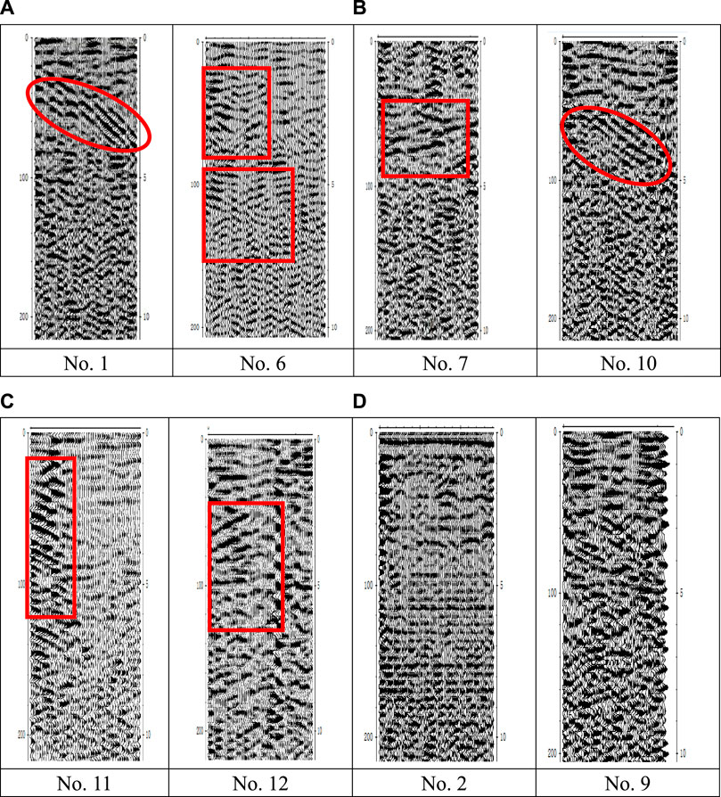
FIGURE 12. The radar detection after grouting; (A) Left lane; (B) Right lane; (C) Side road; (D) Left and right lanes.
This study focuses on a comparative analysis of various grouting pastes and evaluate their application on the grouting effect of goaf treatment based on the grouting backfilling method. The study begins with a discussion about the properties of different grouting pastes, including clay-cement composite grouting material and geopolymer grouting material. The study also examines the factors that affect the performance of grouting pastes, such as water-solid ratio and curing time. Besides, based on the detailed information about the boreholes by drilling television, a reasonable treatment plan could be formulated for goaf treatment. Finally, this study presents an evaluation of the grouting effect of different grouting pastes based on their application in actual goaf treatment projects. The following conclusions are mainly drawn:
(1) There is a direct relationship between the flowability and setting time of clay-cement composite grouting material and geopolymer grouting material and the water-solid ratio, as the water-solid ratio increases, the rate of increase in flowability increases at first and then decreases, the final setting time also increases.
(2) Under the same curing age conditions, there is an inverse relationship between the compressive strength of grouting materials and the water-solid ratio. As the water-solid ratio increases, the compressive strength of grouting materials also decreases.
(3) Drilling data show that the goaf structure is complex, there are some goaf defects such as water leakage, collapse and cavity, even underground tunnel, which indicating that geological risks may exist in shallow areas.
(4) A treatment plan is formulated based on the geological conditions of goafs by drilling television. The water-solid ratio for geopolymer grouting material was 0.35. Clay-cement composite grouting material was made up with a water-solid ratio of 0.6 and bentonite content of 20%.
(5) Using GPR technology, the effectiveness of backfill grouting in goaf areas is inspected, and the GPR results showed that the grouting treatment effect has achieved good effect. This study found that adjusting the water-solid ratio of the grouting material can improve treatment effects.
There are still many issues and topics about goaf treatment based on grouting backfilling method, including grouting materials and treatment evaluation. As a continuation of this paper, the novel sustainable grouting materials will be investigated in the future studies. Meanwhile, the intelligent detection and evaluation of goaf should be deeply investigated.
The original contributions presented in the study are included in the article/Supplementary material, further inquiries can be directed to the corresponding authors.
ZQ: Conceptualization, Investigation, Methodology, Writing–original draft. QS: Formal Analysis, Investigation, Validation, Writing–review and editing. DQ: Formal Analysis, Investigation, Writing–review and editing. HW: Investigation, Validation, Writing–original draft. YL: Formal Analysis, Validation, Writing–review and editing. WW: Conceptualization, Formal Analysis, Funding acquisition, Methodology, Project administration, Writing–review and editing.
The author(s) declare financial support was received for the research, authorship, and/or publication of this article. This research was funded by the Guangxi Science and Technology Base and Talent Project (grant number: AD23026015), Scientific Research Project of the Department of Education of Jilin Province (grant number: JJKH20241300KJ), the Fundamental Research Funds for the Central Universities, Postdoctoral Researcher Selection Funding Project of Jilin Province.
The authors are grateful for the support.
Authors ZQ, QS, and DQ were employed by Guangxi Baining Expressway Co., Ltd.
Author HW was employed by Guangxi Transportation Science and Technology Group Co., Ltd.
Author YL was employed by Hualan Design and Consulting Group Company Ltd.
The remaining author declares that the research was conducted in the absence of any commercial or financial relationships that could be construed as a potential conflict of interest.
All claims expressed in this article are solely those of the authors and do not necessarily represent those of their affiliated organizations, or those of the publisher, the editors and the reviewers. Any product that may be evaluated in this article, or claim that may be made by its manufacturer, is not guaranteed or endorsed by the publisher.
Allouzi, R., Almasaeid, H., Alkloub, A., Ayadi, O., Allouzi, R., and Alajarmeh, R. (2023). Lightweight foamed concrete for houses in Jordan. Case Stud. Constr. Mat. 18, e01924. doi:10.1016/j.cscm.2023.e01924
Cao, B., Wang, J., Du, H., Tao, Y. B., and Liu, G. W. (2022). Research on comprehensive detection and visualize of hidden cavity goaf. Sci. Rep-Uk 12 (1), 22309. doi:10.1038/s41598-022-26680-3
China Water Power Press (2014). Technical specification for cement grouting of hydraulic structures (SL62-2014). Beijing: China Water Power Press.
Duan, D. D., Wu, H. B., Wei, F., Song, H. P., Chen, Z., Cheng, F. Q., et al. (2023). Preparation, characterization, and rheological analysis of eco-friendly geopolymer grouting cementitious materials based on industrial solid wastes. J. Build. Eng. 78, 107451. doi:10.1016/j.jobe.2023.107451
Dun, Z. L., Wang, M. Q., Zou, Y. F., and Ren, L. W. (2022). Laboratory tests on performance of waste-clay-brick-powder cement grouting materials for ground improvement in mine goaf. Adv. Eng. Mater 24 (8). doi:10.1002/adem.202101575
Feng, X., Xia, C., Zhang, S. F., Li, C. G., Zhao, H. K., Wu, J. F., et al. (2022). Properties and engineering applications of a new goaf grouting filling material. Geofluids 2022, 1–14. doi:10.1155/2022/6778076
Guo, Q. B., Li, Y. M., Meng, X. R., Guo, G. L., and Lv, X. (2019). Instability risk assessment of expressway construction site above an abandoned goaf: a case study in China. Environ. Earth Sci. 78 (20), 588. doi:10.1007/s12665-019-8599-z
Guo, Q. B., Meng, X. R., Li, Y. M., Lv, X., and Liu, C. (2021). A prediction model for the surface residual subsidence in an abandoned goaf for sustainable development of resource-exhausted cities. J. Clean. Prod. 279, 123803. doi:10.1016/j.jclepro.2020.123803
Han, C. P., Zu, F. J., Du, C., and Shi, L. (2022). Analysis of excavation stability and reinforcement treatment of the cutting slope under the influence of old goaf. Appl. Sci-Basel 12 (17), 8698. doi:10.3390/app12178698
Hebblewhite, B. K., and Lu, T. (2004). Geomechanical behaviour of laminated, weak coal mine roof strata and the implications for a ground reinforcement strategy. Int. J. Rock Mech. Min. 41 (1), 147–157. doi:10.1016/j.ijrmms.2003.08.003
Huang, S. J., Zhao, G. M., Meng, X. R., Cheng, X., Gu, Q. H., Liu, G., et al. (2022). Development of cement-based grouting material for reinforcing narrow coal pillars and engineering applications. Processes 10 (11), 2292. doi:10.3390/pr10112292
Kadela, M., Kukielka, A., and Malek, M. (2020). Characteristics of lightweight concrete based on a synthetic polymer foaming agent. Materials 13 (21), 4979. doi:10.3390/ma13214979
Li, L. S., Qian, D. Y., Yang, X. G., and Jiao, H. X. (2022). Pressure relief and bolt grouting reinforcement and width optimization of narrow coal pillar for goaf-side entry driving in deep thick coal seam: a case study. Minerals-Basel 12 (10), 1292. doi:10.3390/min12101292
Li, X. L., Wei, S. J., and Wang, J. (2022). Study on mine pressure behavior law of mining roadway passing concentrated coal pillar and goaf. Sustainability-Basel 14 (20), 13175. doi:10.3390/su142013175
Lim, S. K., Tan, C. S., Lim, O. Y., and Lee, Y. L. (2013). Fresh and hardened properties of lightweight foamed concrete with palm oil fuel ash as filler. Constr. Build. Mater. 46, 39–47. doi:10.1016/j.conbuildmat.2013.04.015
Liu, Z. J., Deng, D. Q., Feng, J. F., Wang, R. Z., Fan, J. K., and Ma, Y. F. (2022). Study on natural settlement index characteristics of iron-bearing tailings applied to goaf filling treatment. Sustainability-Basel 14 (17), 10739. doi:10.3390/su141710739
Marian, D. P., Onica, I., Marian, R. R., and Floarea, D. A. (2020). Finite element analysis of the state of stresses on the structures of buildings influenced by underground mining of hard coal seams in the jiu valley basin (Romania). Sustainability-Basel 12 (4), 1598. doi:10.3390/su12041598
Shaheen, Y. B., Eltaly, B. A., Yousef, S. G., and Fayed, S. (2023). Structural performance of ferrocement beams incorporating longitudinal hole filled with lightweight concrete. Int. J. Concr. Struct. M. 17 (1), 21. doi:10.1186/s40069-023-00579-3
Shi, X. N., Huang, J. J., and Su, Q. (2020). Experimental and numerical analyses of lightweight foamed concrete as filler for widening embankment. Constr. Build. Mater. 250, 118897. doi:10.1016/j.conbuildmat.2020.118897
Shrestha, R., Redmond, L., and Thompson, J. J. (2022). Diagonal tensile strength and lap splice behavior of concrete masonry assemblies with lightweight grout. Constr. Build. Mater. 344, 128141. doi:10.1016/j.conbuildmat.2022.128141
Song, H. Q., Xu, J. J., Fang, J., Cao, Z. G., Yang, L. Z., and Li, T. X. (2020). Potential for mine water disposal in coal seam goaf: investigation of storage coefficients in the Shendong mining area. J. Clean. Prod. 244, 118646. doi:10.1016/j.jclepro.2019.118646
Song, Y., and Lange, D. (2021). Influence of fine inclusions on the morphology and mechanical performance of lightweight foam concrete. Cem. Concr. Comp. 124, 104264. doi:10.1016/j.cemconcomp.2021.104264
Standards Press of China (2011). Test methods for water requirement of normal consistency, setting time and soundness of the portland cement (GB/T 1346-2011). Beijing: Standards Press of China.
Wang, C. X., Lu, Y., Qin, C. R., Li, Y. Y., Sun, Q. C., and Wang, D. J. (2019). Ground disturbance of different building locations in old goaf area: a case study in China. Geotech. Geol. Eng. 37 (5), 4311–4325. doi:10.1007/s10706-019-00909-x
Wang, H., Li, Y., Dun, Z. Y., Cheng, J. H., Dun, Z. L., and Wu, C. X. (2022). Seepage grouting mechanism for foundations in goaf sites considering diffusion paths. Geofluids 2022, 1–14. doi:10.1155/2022/8394811
Wang, X., Zhang, J., Li, M., Huo, B., and Jin, L. (2023). Experimental study on performance optimization of grouting backfill material based on mechanically ground coal gangue utilizing urea and quicklime. Mater. (Basel) 16 (3), 1097. doi:10.3390/ma16031097
Xu, C. Y., Han, L. J., Tian, M. L., Wang, Y. J., and Jin, Y. H. (2020). Study on foamed concrete used as gas isolation material in the coal mine goaf. Energies 13 (17), 4377. doi:10.3390/en13174377
Yang, Y. M., Chen, Z., Feng, W. H., Nong, Y. M., Yao, M. H., and Tang, Y. C. (2021). Shrinkage compensation design and mechanism of geopolymer pastes. Constr. Build. Mater. 299, 123916. doi:10.1016/j.conbuildmat.2021.123916
Yang, Y. M., Fang, S., Feng, W. H., Wan, S., Li, L. J., and Tang, Y. C. (2023). Flexural and compressive performance of BFRP-reinforced geopolymer sea-sand concrete beams and columns: experimental and analytical investigation. Compos Struct. 318, 117089. doi:10.1016/j.compstruct.2023.117089
Yang, Y. M., Feng, W. H., Qiu, J. J., Guan, S. H., and Tang, Y. C. (2022). Study of shrinkage compensation and feasibility of engineering applications of geopolymer concrete. J. Mater. Civ. Eng. 34 (5). doi:10.1061/(asce)mt.1943-5533.0004177
Yu, Y., Bai, J. B., Wang, X. Y., and Zhang, L. Y. (2020). Control of the surrounding rock of a goaf-side entry driving heading mining face. Sustainability-Basel 12 (7), 2623. doi:10.3390/su12072623
Yuan, L. X., Zhang, C., Wang, C. X., Wei, N., Wan, J., Zhu, C. H., et al. (2022). Effect of the crosslinking degree on the microstructure and thermomechanical properties of a polymer grouting material. Polymer 259, 125342. doi:10.1016/j.polymer.2022.125342
Zhang, C. R., Yang, X. C., Ren, G. F., Ke, B., and Song, Z. L. (2019). Instability of gypsum mining goaf under the influence of typical faults. Ieee Access 7, 88635–88642. doi:10.1109/access.2019.2925810
Zhang, S. K., Jiang, P., Lu, L., Wang, S., and Wang, H. H. (2022). Evaluation of compressive geophysical prospecting method for the identification of the abandoned goaf at the tengzhou section of China's Mu Shi expressway. Sustainability-Basel 14 (21), 13785. doi:10.3390/su142113785
Zhang, Z. Y., and Shimada, H. (2018). Numerical study on the effectiveness of grouting reinforcement on the large heaving floor of the deep retained goaf-side gateroad: a case study in China. Energies 11 (4), 1001. doi:10.3390/en11041001
Zhou, S. Q., Yang, Z. N., Zhang, R. R., and Li, F. (2021). Preparation, characterization and rheological analysis of eco-friendly road geopolymer grouting materials based on volcanic ash and metakaolin. J. Clean. Prod. 312, 127822. doi:10.1016/j.jclepro.2021.127822
Keywords: goaf treatment, grouting backfilling method, geopolymer grouting paste, claycement grouting paste, grouting fillers from solid waste
Citation: Qin Z, Shi Q, Qin D, Wang H, Luo Y and Wang W (2023) Performance comparison of geopolymer and clay-cement grouting pastes and goaf effect evaluation of grouting backfilling method. Front. Mater. 10:1301504. doi: 10.3389/fmats.2023.1301504
Received: 27 September 2023; Accepted: 27 November 2023;
Published: 06 December 2023.
Edited by:
Yunchao Tang, Guangxi University, ChinaReviewed by:
Jue Li, Chongqing Jiaotong University, ChinaCopyright © 2023 Qin, Shi, Qin, Wang, Luo and Wang. This is an open-access article distributed under the terms of the Creative Commons Attribution License (CC BY). The use, distribution or reproduction in other forums is permitted, provided the original author(s) and the copyright owner(s) are credited and that the original publication in this journal is cited, in accordance with accepted academic practice. No use, distribution or reproduction is permitted which does not comply with these terms.
*Correspondence: Haihua Wang, d2FuZ2hhaWh1YTIwMDBAb3V0bG9vay5jb20=; Wensheng Wang, d2FuZ3dzQGpsdS5lZHUuY24=
Disclaimer: All claims expressed in this article are solely those of the authors and do not necessarily represent those of their affiliated organizations, or those of the publisher, the editors and the reviewers. Any product that may be evaluated in this article or claim that may be made by its manufacturer is not guaranteed or endorsed by the publisher.
Research integrity at Frontiers
Learn more about the work of our research integrity team to safeguard the quality of each article we publish.