 Peibo You1
 Li Li
Li Li- 1Department of Civil and Transportation Engineering, Henan University of Urban Construction, Pingdingshan, Henan, China
- 2College of Water Resources and Architectural Engineering, Northwest A&F University, Yangling, China
- 3Department of Architectural Engineering, Jiyuan Vocational and Technical College, Jiyuan, Henan, China
In the paper, an innovative shear wall, which is referred to as steel fiber reinforced concrete (SFRC) shear wall with concrete filled steel tube (CFST) columns, is introduced, based on the high bearing capacity and large stiffness of concrete filled steel tube column (CFSTC) and good cracking resistance and strong toughness of steel fiber reinforced concrete. The loading mechanism of steel fiber reinforced concrete shear wall (SFRCSW) with concrete filled steel tube columns is analyzed, and shear bearing capacity calculation method. A simplified model of the steel fiber reinforced concrete shear wall web softening tension bar is proposed, concrete and distributed web reinforcement to the shear bearing capacity of steel fiber reinforced concrete shear wall web is identified. Furthermore, a new algorithm to obtain the shear bearing capacity of steel fiber reinforced concrete shear wall with concrete filled steel tube columns is established, and then it is validated by using the test results of steel fiber reinforced concrete shear wall with concrete filled steel tube columns under low-cycle repeated loading. The results showed that all tested shear wall specimens exhibited obvious shear failure characteristics and a typical diagonal cracking pattern after test. The steel fibers obviously improved the crack forms of the steel fiber reinforced concrete shear wall web and the seismic behavior of steel fiber reinforced concrete shear wall with concrete filled steel tube columns. In addition, the proposed calculation method is scientific and accurate to analyze and predict the shear bearing capacity of low-rise steel fiber reinforced concrete shear wall with concrete filled steel tube columns.
1 Introduction
Reinforced concrete (RC) shear wall is a common anti-lateral force component in high-rise building that has been widely used in high-frequent earthquake prone area. The observation from recent earthquake reconnaissance indicated that the main reason why the RC shear wall was seriously damaged and even collapsed was its inadequate ductility and energy dissipation (Coull and Puri, 1967; Brunesi et al., 2018; Brunesi et al., 2019; Demirel et al., 2023; Ju et al., 2023; Xu et al., 2023). There are many problems that need to be solved urgently in the existing ordinary reinforced concrete shear walls located in high-intensity earthquake areas. In the current design code, the axial compression ratio of RC shear walls at the bottom of high-rise buildings needs to be strictly limited to meet the ductility requirements and avoid brittle failure. Therefore, the designed wall web is often very thick, which not only reduces the useable area and space of building, but also increases the self-weight of structure and construction cost. On the other hand, the restrained edge members of ordinary RC shear walls must be equipped with a large number of stirrups to effectively restrain concrete and prevent longitudinal reinforcement from buckling under compression. But intensive reinforcement of RC shear wall not only increases construction cost, but also affects construction quality.
The research shows that there are two main reasons for the insufficient ductility and energy dissipation performance of ordinary RC shear walls. First, the longitudinal reinforcements in the restrained edge members of RC shear wall yield prematurely, which leads to rapid degradation of the flexural capacity of RC shear wall. Second, the shear bearing capacity of the wall degrades rapidly after the concrete at the bottom of RC shear wall is crushed and peeled off, which reduces the energy dissipation capacity of RC shear wall. In order to improve the ductility and energy dissipation performance of ordinary RC shear walls, some new improvement measures have been put forward one after another, such as improving the reinforcement ratio and increasing the numbers of wall reinforcement, shear wall with vertical joint, shear wall with horizontal joint, shear wall with concealed bracing and steel reinforced concrete shear wall. However, the improvement of ductility and energy dissipation capacity of RC shear walls cannot simply rely on increasing the distribution reinforcement ratio, which will increase the construction difficulty, the joints in the wall web easily weaken the shear wall section, the addition of concealed bracing in the wall web easily lead complexity of wall reinforcement mode. In particular, along with the widespread application of high strength concrete (HSC), the cross-section size of shear wall can be decreased, but the brittleness of reinforced high strength concrete (RHSC) shear wall increases inexorably. Correspondingly, the seismic behavior of RHSC shear wall needs to be improved to meet the higher requirement (Athanasopoulou, 2010; Beyer et al., 2011; Li et al., 2023a; Li et al., 2023b). Nowadays, the research work focuses on the following two aspects to get better seismic performance of RHSC shear wall.
Firstly, the structural form innovation is adopted to improve the seismic performance of RHSC shear wall. Among the above measures used, it is feasible to set concrete filled steel tube (CFST) columns on both sides of the RC shear wall to form RC shear wall with CFSTCs, which can give full play to the advantages of the performance of steel tube and concrete (Han et al., 2009; Wu et al., 2018; Todea et al., 2021; Li et al., 2022; Yin et al., 2022; Yang et al., 2023), and greatly improve the bearing capacity of the RC shear wall (Shirali, 2002; Vetr et al., 2016). The test and theoretical study show that the CFST column (CFSTC) can effectively restrain the middle RC wall web, improve the crack shape of RC wall web, and still bear part of the load after the RC wall web gradually degenerates, indicating that the existence of the CFSTCs can make the RC shear wall form a dual channel seismic defense line and have good seismic behavior. Therefore, RC shear wall with CFSTCs is becoming more and more popular around the engineering practice in recent years.
Secondly, the latest research results of scholars at home and abroad show that adding steel fiber into concrete can effectively improve the seismic performance of RC members, including the RHSC shear wall (Bekő et al., 2015; Peng et al., 2015; Li et al., 2016; Li et al., 2023c). The seismic behavior of steel fiber reinforced concrete (SFRC) shear walls subjected to reversed cyclic loading have been tested by several scholars (Zhou et al., 2018; Lou et al., 2021; Zadeh et al., 2021; Zhang et al., 2022). Just as anticipated, because the randomly distributed steel fibers can effectively improve anti-cracking property, tensile strength, shearing property, toughness, durability and seismic performance of matrix concrete, they can greatly improve the seismic performance of SFRCSW (SFRCSW), reduce the degree of reinforcement aggregation, and increase construction efficiency (Li et al., 2023d; Li et al., 2023e; Gu et al., 2023). With the increase of the volume ratio of steel fiber, the bearing capacity, ductility and energy dissipation capacity of SFRCSW increase.
In this paper, a new kind of double composite shear wall referred to as SFRCSW with CFSTCs is introduced, which includes SFRCSW web and CFST boundary elements. In this new composite shear wall, the addition of steel fiber is helpful to improve the fracture properties of HSC, and using a steel tube as confinement can significantly improve the ductility and compressive strength of core concrete. SFRC web can improve its ductility and energy dissipation capacities, CFST boundary elements can enhance its load bearing capacity and rigidity. This kind of composite shear wall can adequately make use of the advantages of SFRC shear web and CFSTCs. Up to now, the project team has made rich research achievements in the early experimental study on the new composite shear wall, but the research results on mechanical mechanism and calculating method for shear bearing capacity of SFRCSW with CFSTCs are relatively few since the mechanical mechanism of the new composite shear wall subjected to the combined action of bending, compression and shear is very complicated. Moreover, determining the respective roles of steel tubes and steel fibers in concrete poses a complex challenge. Additionally, the calculating methods for shear bearing capacity of SFRCSW proposed in the existing literature are almost universally half-empirical equation based on test results, and there is no scientific and reasonable theoretical model (Liu et al., 2022). And ultimately, the calculation results for shear bearing capacity of SFRCSW with CFSTCs are not accurate enough.
The simplified softened strut-and-tie model for calculating the shear bearing capacity of RC elements damaged by inclined compression bar was established by Hwang and Lee (1999), Hwang and Lee (2002), which derived from the concept of strut and tie of RC elements, introducing a softening coefficient of concrete. And the equations satisfying the equilibrium, coordination and constitutive relation of cracked reinforced concrete were put forward. The shear bearing capacity prediction of different types of RC concrete members has been calculated by used the SSTM, and the calculation accuracy has been verified by comparing calculated shear bearing capacity with test results reported in previous literatures (Cardenas et al., 1973; Su and Wong, 2007; Jalali and Dashti, 2010).
In this paper, the loading mechanism of SFRCSW with CFSTCs is analyzed, and the shear bearing capacity of the SFRCSW with CFSTCs can be calculated by the superposition of the shear capacity of the CFSTCs and the SFRCSW web. The simplified softened strut-and-tie model of SFRCSW web composed of diagonal strut, horizontal and vertical resistant members is proposed, in which the contributions of steel fiber, concrete and distributed web reinforcement to the shear bearing capacity of SFRCSW web is identified. The randomly distributed steel fibers in SFRCSW web can be equivalent to horizontal and vertical finely distributed steel bars in the shear bearing capacity analysis of SFRCSW web. Furthermore, a new algorithm to obtain the shear bearing capacity of SFRCSW with CFSTCs is established, and then it is validated by using the test results of 11 low-rise SFRCSW with CFSTCs under low-cycle repeated loading. The results show that the calculated values are in good agreement with the experimental values for the 11 low-rise shear walls, and the proposed algorithm can be used to calculate the shear bearing capacity of SFRCSW with CFSTCs.
2 Loading mechanism of SFRCSW with CFSTCs
The previous test research showed that all low-rise SFRCSW with CFSTCs specimens exhibited obvious shear failure characteristics and a typical diagonal cracking pattern after test (Hwang and Lee, 1999; Zhao and Astaneh-Asl, 2004; Yang et al., 2011). The shear force transmission process of shear wall specimens can be roughly divided into two stages. In the early loading stage, the bending moment acting on the SFRCSW with CFSTCs specimens was borne by the CFSTCs, the horizontal shear was borne by the SFRCSW web, and the axial force was shared by the CFSTCs and the SFRCSW web. In the middle and late loading stage, the concrete cracks continued to develop, the stiffness of SFRCSW web gradually decreased, and the shear force transferred from shear wall web to CFSTCs. Therefore, the shear bearing capacity of shear wall with CFSTCs specimen is composed of two parts: CFSTCs and SFRCSW web.
And the SFRCSW web under the action of compression, bending and shearing formed intersecting oblique pressure and tension flow along the diagonal direction, as represented in Figure 1 above. The oblique pressure was borne by wall web concrete, forming a diagonal compression bar mechanism. And the oblique tension was mainly borne by the horizontal tie rod composed of horizontally distributed reinforcements and randomly distributed steel fibers and the vertical tie rod composed of vertically distributed reinforcements and randomly distributed steel fibers. Thus, a strut and tie action of SFRCSW web had been produced.
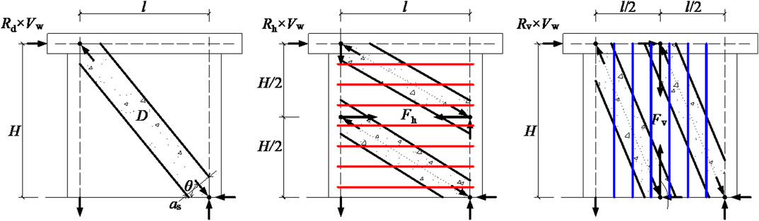
FIGURE 1. Shear resisting mechanisms of SFRCSW web.
3 Calculation method for shear bearing capacity of SFRCSW with CFSTCs
3.1 Shear bearing capacity of CFSTCs
The shear bearing capacity of the SFRCSW with CFSTCs Vj can be calculated by the superposition of the shear capacity of the CFSTCs and the SFRCSW web according to the above analysis, shown as Eq. (1):
where Vw is the shear bearing capacity of SFRCSW web; Vcol is the shear bearing capacity of CFSTCs.
The shear bearing capacity of CFSTCs Vcol can be defined as Peng et al. (2015) (Eq. 2):
where αv is the shear coefficient of CFSTCs, αv = 0.97 + 0.2In(ξ), ξ is the steel tube confinement factor, ξ = αafya/fc, fya is the steel yield strength, fc is the axial compressive strength of concrete, αa is the steel ratio of CFSTC, αa = Aa/Aco, Aa and Aco are the cross-sectional areas of steel tube and core concrete in pipe, respectively; Asc is the total cross-sectional area of CFSTC; τscy is the shear yield strength, τscy = (0.422 + 0.313αa2.33) ξ0.134 (1.14 + 1.02ξ) fc.
3.2 Shear bearing capacity of SFRCSW web
The preliminary test results indicate that the steel fibers have not changed the loading mechanism of the shear wall, the loading mechanism of SFRCSW is similar to that of RC shear wall. According to the stress characteristics of the SFRCSW web, the randomly distributed steel fibers in shear wall web can be equivalent to horizontal and vertical finely distributed steel bars based on the simplified softened strut and tie model. Thus, the simplified softened strut and tie model of SFRCSW is composed of diagonal resistance mechanism, horizontal resistance mechanism and vertical resistance mechanism, as shown in Figure 1 above.
The inclination of diagonal compression bar mechanism for SFRC θ can be determined by Eq. (3):
where H is the SFRCSW web height; l is internal force arm of vertical couple of SFRCSW web, l = 0.9h, h is the section height of SFRCSW web.
The cross-sectional area of the diagonal compression bar, Astr, can be defined as Eq. (4):
where αstr is the section height of diagonal compression bar; bstr is the section width of diagonal compression bar, which is consistent with the wall section width b.
The section height of diagonal compression bar αstr can be roughly defined as Eq. (5):
where N ′ is the axial compressive force borne by the SFRCSW web; fc' is the compressive strength of a standard concrete cylinder (MPa).
The axial compressive force borne by the SFRCSW web N′ can be determined by Eq. (6):
where N is the axial compressive force borne by the SFRCSW with CFSTCs specimen; Ec is the elastic modulus for SFRCSW web concrete; Ea is the elastic modulus of steel tube; Eco is the elastic modulus of core concrete.
In Figure 1B, one horizontal tie rod and two flat struts form the horizontal force mechanism. And the horizontal tie rod value Fh can be defined as Eq. (7):
where Fh is the horizontal tie rod value; Fs, h is the horizontally distributed reinforcement tie rod tension force value, many test results showed that the horizontally distributed reinforcements in the wall web did not fully yield when the shear wall specimen failed, so the effective coefficient, η1, is suggested in the background, thus Fs, h = η1×As, h×fs, h, η1 is the effective shear resistance coefficient of horizontally distributed reinforcement, which can be approximately designated as 0.75 according to the study in the literature (Jalali and Dashti, 2010); and As, h is the cross sectional area of horizontally distributed reinforcements tie rod, fs, h is the tension strength of horizontally distributed reinforcement; Fsf, h is the horizontally distributed steel fibers tie rod tension force value, Fsf, h = Asf, h×fsf, Asf, h is the cross sectional area of horizontally distributed steel fibers tie rod, fsf is the tension strength of horizontally distributed steel fiber.
In order to reduce the cost of computation, the randomly distributed steel fibers in the three dimensions of the SFRCSW web can be equivalent to horizontally and vertically finely distributed steel bars in the shear bearing capacity analysis of SFRCSW, as shown in Figure 2. So the cross sectional area of horizontally distributed steel fibers tie rod, Asf, h, can be determined by Eq. (8):
where Asf is the cross-sectional area of a single steel fiber; nsf is the number of equivalent horizontal steel fibers, which can be determined by Eq. (9):
where ρf is the volume ratio of steel fiber; η2 is the equivalent reduction coefficient, which can be approximately taken as 0.41 based on the analysis for the experimental results in the literature (Gonzales and López-Almansa, 2012).
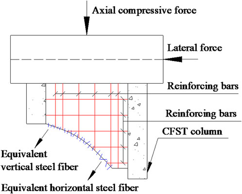
FIGURE 2. Steel fiber ties.
The cross-sectional area of horizontally distributed steel fibers tie rod, Asf, h, can be calculated by Eq. (10):
In Figure 1C, one vertical tie rod and two steep struts form the vertical force mechanism. And the vertical tie rod value Fv and can be defined as the following Eq. (11):
where Fv is the vertical tie rod value; Fs, v is the vertically distributed reinforcement tie rod tension force value, many existing test results showed that the vertically distributed reinforcements in the wall web did not fully yield when the shear wall specimen failed, so the effective coefficient, η3, is suggested in the background, thus Fs, v = η3×As, v×fs, v, η3 is the effective shear resistance coefficient of vertically distributed reinforcement, which can be approximately designated as 0.80 according to the study in the literature (Jalali and Dashti, 2010); and As, v is the cross sectional area of vertically distributed reinforcements tie rod, fs, v is the tension strength of vertically distributed reinforcement; Fsf, v is the vertically distributed steel fibers tie rod tension force value, Fsf, v = Asf, v×fsf, Asf, v is the cross sectional area of vertically distributed steel fibers tie rod, and Asf, v = 0.41ρfbh/cosθ according to the above analysis, fsf is the tension strength of vertically distributed steel fiber.
The horizontal shear resistance capacity value of SFRCSW web Vw is distributed to the three resistance mechanisms in a certain proportion (Jalali and Dashti, 2010), shown as Eq. (12):
where D is the pressure value of SFRC diagonal compression bar; Rd, Rh, and Rv are the horizontal shear resistance capacity ratios borne by diagonal, horizontal and vertical resistance mechanisms, respectively, which can be calculated by Jalali and Dashti (2010)(Eq. 13):
where γh is the ratio of horizontal shear resistance capacity value borne by the horizontal tie rod when the vertical resistance mechanism does not participate in shear resistance capacity distribution; γv is the ratio of vertical shear resistance capacity value borne by the vertical tie rod when the horizontal resistance mechanism does not participate in shear resistance capacity distribution. The values of γh and γv can be calculated by Mullapudi et al. (2013) (Eq. 14):
The failure criterion of simplified strut and tie model for the SFRCSW web is that the resultant force of diagonal compression strut, flat compression strut and steep compression strut at the joint region reaches the concrete compression strength as shown in Figure 1. In order to judge whether the SFRCSW web was damaged, the resultant force at the joint region must be checked. The maximum compressive stress σd, max generated by the three compression struts at the joint region can be defined as Eq. (15):
The stress-strain relationship of the distributed reinforcement in the SFRCSW web can be expressed as Eq. (16):
where Es is the elastic modulus of the distributed reinforcements; fy and εy are the yield strength and yield strain of the distributed reinforcements respectively; fs and εs are the actual stress and actual strain of the distributed reinforcements respectively; the only caveat here is that when the above calculation Equation 16 is applied to the horizontally distributed reinforcements and the vertically distributed reinforcements respectively, fs is taken as fs, h or fs, v, Es is taken as Es, h or Es, v, εs is taken as εs, h or εs, v, and fy is taken as fy, h or fy, v.
The stress-strain relationship of the randomly distributed steel fibers in the three dimensions of the SFRCSW web can be described as Eq. (17):
where Esf and εsf are the elastic modulus and actual strain of the randomly distributed steel fibers in the three dimensions of the SFRCSW web, respectively.
The existing test results have indicated that most of the randomly distributed steel fibers in the wall web are pulled out from the matrix concrete rather than damaged as a result of their good mechanical properties. Therefore, the tension strength of the randomly distributed steel fibers in the wall web, fsf, generally depends on the bonding strength between steel fiber and matrix concrete. And the following functional Eq. (18) relationship needs to be satisfied :
where λsf is the effective coefficient of steel fiber type, and the values of λsf for long straight, wave-shaped, and hooked steel fibers are 0.5, 0.75, and 1.0, respectively; τsf, max is the maximum bonding strength between steel fiber and matrix concrete, and according to the existing research results in literature (Hidalgo et al., 2002), τsf, max can be considered equal to 2.5fct here, fct is the matrix tension strength of SFRC; Aspf is the surface area of steel fiber, Aspf = πdflsfo, df and lsfo are the equivalent diameter and the effective bounding length of steel fiber respectively, and lsfo = 0.25 lf, lf is the length of steel fiber.
Thus, the tension strength of the randomly distributed steel fibers in the wall web fsf can be described as the following according to the Eq. (19):
In summary, the relationship between tension force values and strains of tie rod can be expressed as Eqs (20–22):
where εs,h and εsf,h are the strains of the horizontally distributed reinforcements and steel fibers, respectively; εs,v and εsf,v are the strains of the vertically distributed reinforcements and steel fibers, respectively; εh and εv are the average horizontal strain and the average vertical strain of the SFRC wall web, respectively; Fyh and Fyv are the yield force values of the horizontal and vertical tie rods, respectively.
The research shows that the wall web will only rely on the concrete diagonal compression bar to transmit pressure and bear the shear force when there are no horizontal and vertical reinforcements in the wall, as shown in Figure 3B. If the wall web is equipped with horizontally and vertically distributed reinforcement, the tie rod formed by the two together can support the generation of concrete secondary compression bar, causing more concrete to participate in compression, as shown in Figures 3C, D, thus improving the shear bearing capacity of the wall web. The randomly distributed steel fibers in the wall web can be equivalent to horizontal and vertical finely distributed steel bars, which can further increase the pressure transmission path and improve the shear bearing capacity of the wall web. The contribution of horizontal and vertical reinforcements to the shear value Vw can be reflected by the tension and compression bar index K, shown as Eq. (23).
where Cd is the diagonal compressive strength of shear wall web concrete.
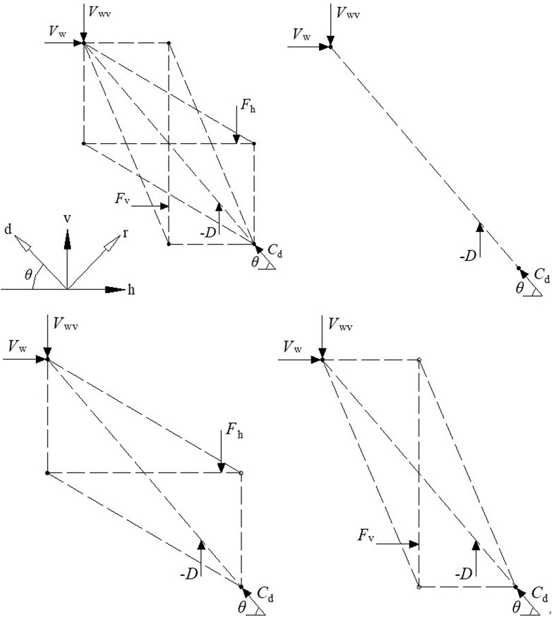
FIGURE 3. Simplified strut and tie model of the SFRC wall web.
Considering the softening effect of concrete, the shear value Vw can be expressed as Eq. (24):
where ζ is the concrete softening coefficient.
The value ζ can be determined by the following (Quiroz et al., 2013) (Eq. 25):
where εr is the average principal tensile strain corresponding to the average principal tensile stress of steel fiber reinforced concrete in the r-direction σr.
According to the principle of strain coordination, the relationship between the critical strains can be expressed by the following (Hung and Lu, 2015) (Eq. 26):
where εd is the average principal compressive strain corresponding to the average principal compressive stress of steel fiber reinforced concrete in the d-direction σd.
And εh = 0.002, εv = 0.002 (Vecchio and Collins, 1993), εd = −0.001 (Hwang et al., 2000), it can be obtained that εr = 0.005.
Thus, the value ζ can be expressed by the following according to the Eq. 27:
3.2.1 Determination of the K value
The simplified softening tension rod model has three resistance mechanisms and four combinations, as shown in Figure 3. The value of K varies depending on the combination method used. In the case where no reinforcing bar is employed in the concrete wall, the tension rod index, Kd, can be determined by utilizing Equation 23. It can be obtained that the index of Kd, the tension rod at this time is shown as Eq. (28):
When considering only the horizontal distribution of reinforcement in the wall, as depicted in Figure 3C, the resistance mechanism of the wall combines both oblique and horizontal forces. If the pressure rod is broken and the horizontal tie rod can still maintain elasticity, the index of the elastic horizontal tie rod
The above equation can be simplified to Eq. (30):
The balance tensile value of the horizontal tie rod
When the horizontal tie rod reinforcement is insufficient, the tensile force provided by it will be less than
In this equation: Fyh should consider the role of steel fiber, and refer to the Equation 20 for calculation:
Similarly, as shown in Figure 3D, the elastic vertical tension bar index
The above equation can be simplified to Eq. (34):
The balance tensile value
When the vertical tie rod reinforcement is insufficient, the vertical tie rod indicator Kv is shown as Eq. (36):
In this equation: Fyh should consider the role of steel fiber, and refer to the Equation 21 for calculation.
When both horizontal and vertical reinforcement bars are configured in the wall, and the pressure rod is broken, and the horizontal and vertical steel bars are not yielded, the index
To simplify the calculation, it can be approximated
Similarly, when the pull rod reinforcement is insufficient, it can be approximated
3.2.2 The solve steps
a)Use Eq. 3 to calculate inclination angle of the diagonal bar
4 Test verification
Table 3 lists the 10 shear wall specimens in this paper and 18 shear wall specimens in related literature (Xingrong et al., 1993; Liao, 2007; Liao et al., 2009; Zhao et al., 2009; Yang et al., 2011), It covers different frame types, geometric dimensions, axial compression ratios, steel pipe shapes, steel fiber volume ratios, concrete strength and reinforcement ratios, The conversion relationship of concrete strength index is calculated according to the literature (Xiaoyan et al., 2014).
The 10 shear wall test pieces designed in this paper, In the specimen number, “RC” represents reinforced concrete shear wall, and “CFST” represents steel tube concrete frame shear wall, the steel pipe section size is hf × hf = 120 × 120 mm, the wall thickness is t = 3 mm. The first number after it indicates the shear span ratio; The second number indicates the steel fiber volume ratio, the brackets following the second number indicate the height of the steel fiber admixture and H is the height of the wall; The third number indicates the concrete design strength grade. In the design strength of concrete, those starting with “C” represent ordinary concrete, while those starting with “CF” represent steel fiber reinforced concrete, 0.1 in parentheses at the end of the number indicates an axial compression ratio of 0.1, 5D stands for steel fiber type as 5D. The meaning of the symbol before the parentheses is the same as described above. There are no other specimens specifically indicated in parentheses at the end of the specimen number, indicating that the axial compression ratio is 0.2, the steel fiber type is 3D, and the loading method is cyclic loading. The type and physical and mechanical properties of steel fiber are shown in Table 1. The steel bars are all made of HRB400 grade, and the steel is made of Q235B. The measured mechanical properties of steel are shown in Table 2. Other design parameters of the shear wall specimen, such as size and reinforcement, are shown in Table 3.
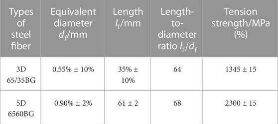
TABLE 1. Physical and mechanical properties of steel fibres.
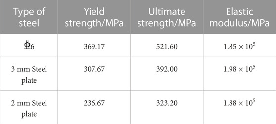
TABLE 2. Mechanical properties of reinforcement and steel.
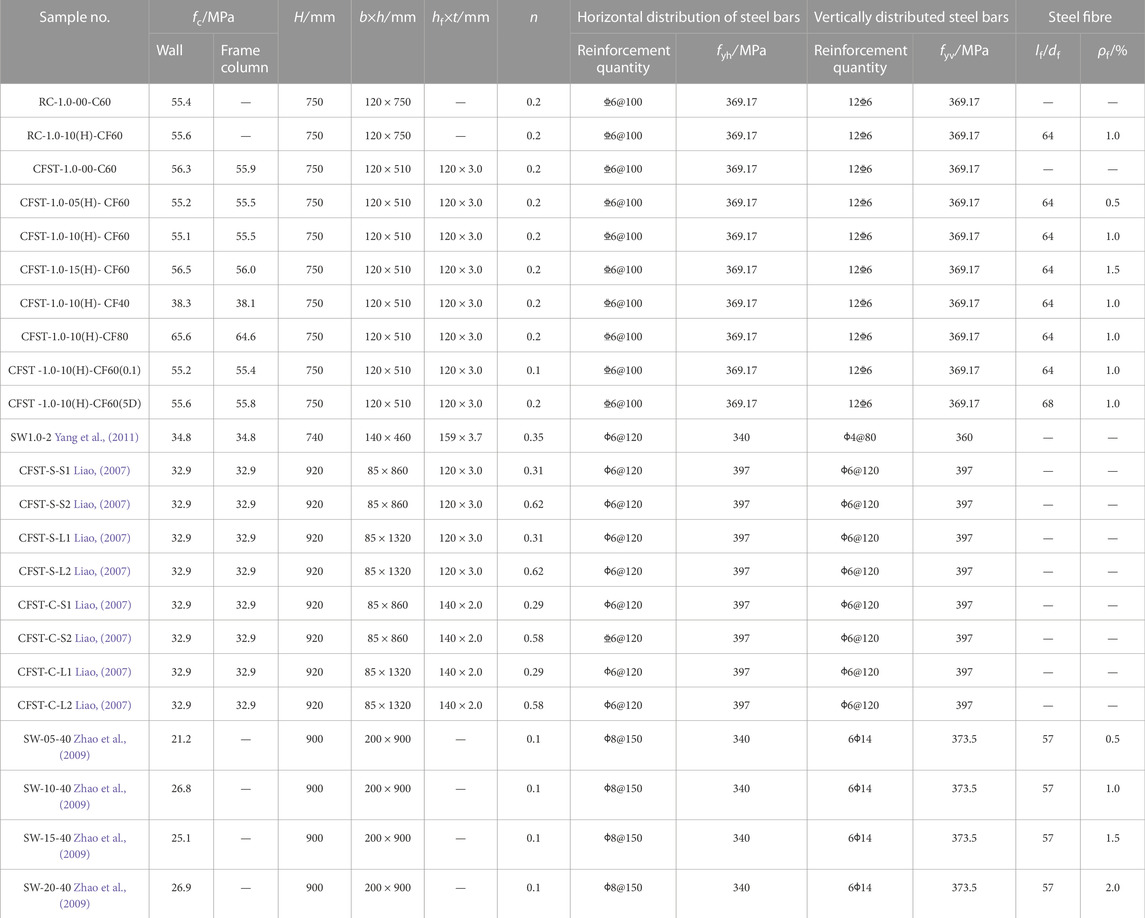
TABLE 3. Shear wall specimen basic information sheet.
After loading, the 10 shear wall specimens mainly showed shear failure (Hidalgo et al., 2002; Hung et al., 2017; Paulay et al., 2022), the crack distributions of them are shown in Figure 4. It can be seen from Figure 4 that the crack development pattern of the shear wall specimen is mainly shear oblique crack. First, one or two oblique cracks appear on the side of the wall under tensile force, which has an angle of about 45° to the horizontal direction, and develops diagonally downward along the diagonal of the wall. As the loading continues, several crossed diagonal downward cracks appear one after another, and the crack width continues to increase. By the late loading stage, most of the oblique cracks of the wall have developed to the root of the wall after they are fully developed, and at the same time, a group or groups of cross-diagonal diagonal cracks with a large width of X shape are gradually formed, and the wall is divided into multiple oblique pressure columns by the oblique cracks, resulting in a failure mechanism similar to the oblique pressure rod. After the shear wall specimen reaches the peak load, the horizontal steel bar basically yields, and the oblique compression column reaches its ultimate compressive strength under the repeated load of tension and compression and is crushed, resulting in the wall concrete constantly crushing and peeling, and the shear wall specimen quickly enters the failure state, and the failure shows the characteristics of brittle failure. Although the frame type (steel tube concrete and reinforced concrete), steel fiber volume ratio, steel fiber type, concrete strength and axial compression ratio and other experimental design parameters of the shear wall specimen are different, However, the specimens of reinforced steel fiber concrete shear wall, steel tube concrete frame, ordinary concrete shear wall and steel tube concrete frame steel fiber high-strength concrete shear wall can be divided into four failure stages in the whole loading process: initial crack, through crack, peak load and limit, The addition of steel pipe and steel fiber did not change the shear failure mode of the shear wall specimen, but only differed in the degree of bending failure of the frame column, the crack morphology of the wall concrete and the overall failure speed of the specimen (Xingrong et al., 1993; Liao et al., 2009; Zhao et al., 2009; Yang et al., 2011).
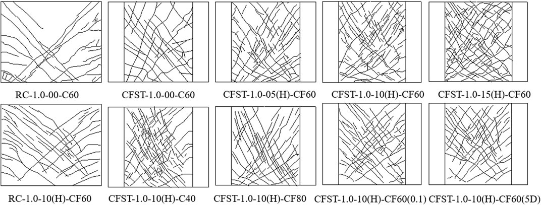
FIGURE 4. Comparison of concrete crack distribution in walls of low-shear wall specimens.
In Figure 5, the shear wall specimen RC-1.0-00-C60 and CFST-1.0-00-C60, the shear wall specimen RC-1.0-10(H)-CF60 and CFST-1.0-10(H)-CF60, the results of the comparative test of the two groups of specimens were all indicate as following. Due to the strong shear resistance of the steel pipe concrete frame, the shear failure surface of the steel pipe concrete frame shear wall is limited to the middle wall, and develops along the diagonal direction of the wall, and finally the wall concrete oblique compression column gradually reaches its ultimate compressive strength and breaks and peels. The steel pipe frame columns on both sides of the back are gradually destroyed under the action of bending and shearing, resulting in the failure of the specimen, and the final failure is that there are more cracks in the wall and a wide distribution area; however, after the diagonal crack of the reinforced concrete shear wall appears, a shear failure surface that penetrates the entire shear wall obliquely is quickly formed, and finally the shear wall slips along the shear failure surface under horizontal load and rapidly fails. The above analysis fully illustrates the strengthening and restraining effect of steel pipe on intermediate wall concrete (Liao, 2007).
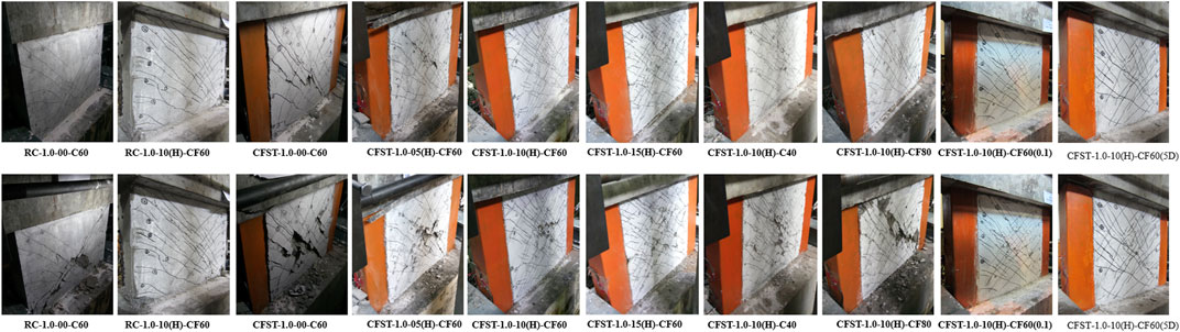
FIGURE 5. The first behavior is the shear wall crack pattern at peak load; the second behavior is the shear wall crack pattern at the end of the test.
Figure 5 also shows that after the incorporation of steel fibers, the development pattern of oblique cracks of concrete walls with or without steel fibers is basically the same. However, due to the reinforcement of steel fiber, with the increase of steel fiber volume rate, the cracks of the shear wall gradually become thinner and denser during peak load. For example, CFST-1.0-00-C60 specimens with steel tubular concrete frame shear wall without steel fiber have a maximum crack width of 2.0 mm at peak load, while steel tube concrete frame shear wall specimens with steel fiber volume ratios of 0.5%, 1.0% and 1.5% CFST-1.0-05(H)-CF60, CFST-1.0-10(H)-CF60 and CFST-1.0-15(H)- The maximum crack width of the CF60 at peak loading is only 1.6 mm, 1.2 mm, and 1.0 mm, respectively; the maximum crack width of RC-1.0-00-C60 RC-1.0-00-C60 without steel fiber reached 2.4 mm under peak load, while the maximum crack width of RC-1.0-10(H)-CF60 with steel fiber volume ratio of 1.0% was only 1.6 mm at peak load. Steel fibers significantly improved the distribution morphology of cracks (The presence of steel fiber reduces the crack spacing and maximum crack width of the wall; when there is no steel fiber, the average spacing of wall cracks is large, the maximum crack width is large, and the wall cracks show the characteristics of few and wide distributions. With the increase of the volume rate of steel fiber, the average spacing and maximum crack width of wall cracks continue to decrease, and wall cracks show fine and dense distribution characteristics. Therefore, the steel fiber can continue to transfer stress across the crack, and its existence can significantly improve the crack morphology.). It limits the width of the main crack, alleviates the crushing and spalling of concrete, and reduces the degree of damage of the shear wall.
Figure 5 also shows that after the incorporation of steel fibers, the development pattern of oblique cracks of concrete walls with or without steel fibers is basically the same. However, due to the reinforcement of steel fiber, with the increase of steel fiber volume rate, the cracks of the shear wall gradually become thinner and denser during peak load. For example, CFST-1.0-00-C60 specimens with steel tubular concrete frame shear wall without steel fiber have a maximum crack width of 2.0 mm at peak load, while steel tube concrete frame shear wall specimens with steel fiber volume ratios of 0.5%, 1.0% and 1.5% CFST-1.0-05(H)-CF60, CFST-1.0-10(H)-CF60 and CFST-1.0-15(H). The maximum crack width of the CF60 at peak loading is only 1.6 mm, 1.2 mm, and 1.0 mm, respectively; the maximum crack width of RC-1.0-00-C60, RC-1.0-00-C60 without steel fiber reached 2.4 mm under peak load, while the maximum crack width of RC-1.0-10(H)-CF60 with steel fiber volume ratio of 1.0% was only 1.6 mm at peak load. Steel fibers significantly improved the distribution morphology of cracks (The presence of steel fiber reduces the crack spacing and maximum crack width of the wall; when there is no steel fiber, the average spacing of wall cracks is large, the maximum crack width is large, and the wall cracks show the characteristics of few and wide distributions. With the increase of the volume rate of steel fiber, the average spacing and maximum crack width of wall cracks continue to decrease, and wall cracks show fine and dense distribution characteristics. Therefore, the steel fiber can continue to transfer stress across the crack, and its existence can significantly improve the crack morphology.). It limits the width of the main crack, alleviates the crushing and spalling of concrete, and reduces the degree of damage of the shear wall.
The Eqs 2, 24 are substituted into the Eq. 1 to obtain the calculation equation of the shear bearing capacity of the shear wall:
According to Eq. 40, the shear bearing capacity of the 28 shear wall specimens in Table 3 was calculated, and the comparison results between the calculated value and the test value are shown in Table 4. The average value of the test value of the shear bearing capacity of the 28 shear wall specimens and the calculated value of Eq. 40 was 1.038, the mean square deviation was 0.144, and the coefficient of variation was 0.139, and the calculated results were in good agreement with the test values.
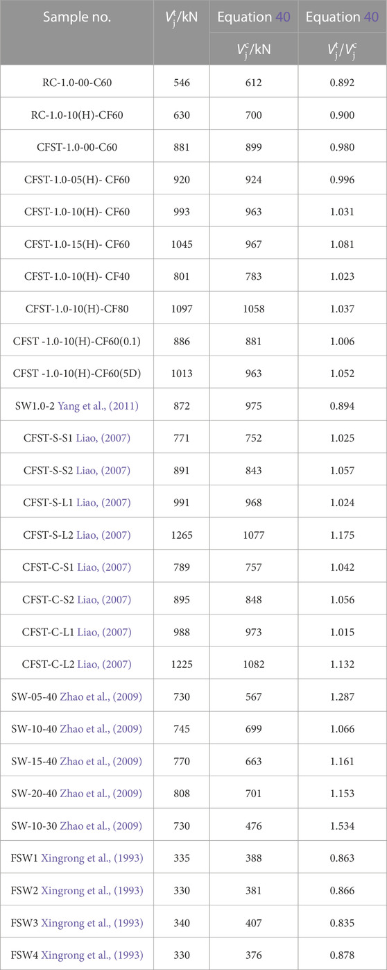
TABLE 4. Comparison of calculated and test results for shear bearing capacity of shear wall specimens.
5 Conclusion
In this paper, a new type of SFRCSW with CFSTC is proposed. The shear wall combines the advantages of steel tube concrete column and reinforced steel fiber high-strength concrete shear wall, which effectively improves the seismic performance of the shear wall such as bearing capacity, ductility and energy dissipation. The following conclusions can be drawn:
(1) The failure mode of low-rise SFRCSW with CFSTC is shear failure. The cracks in of the concrete wall are mainly typical oblique cracks, steel fiber can effectively limit the crack width of the wall concrete, improve the crack morphology, with the increase of the volume rate of steel fiber, the cracks of the shear wall are significantly thinned and dense, the crack distribution area is significantly increased, and the amount of crushing and spalling of the concrete wall is significantly reduced.
(2) The calculation model of the shear bearing capacity of SFRCSW with CFSTC can be calculated by using the superposition of the shear bearing capacity of CFSTC and the shear bearing capacity of SFRCSW. The shear mechanism of the wall plays the comprehensive role of the oblique compression rod-truss mechanism. The randomly distributed steel fibers in concrete can be compared to the reinforcement provided by horizontally and vertically distributed steel bars. To analyze the shear bearing capacity of Steel Fiber Reinforced Concrete with Steel Wires (SFRCSW), a calculation model is developed based on the simplified softening tension rod model. Based on this, the calculation method of shear bearing capacity of SFRCSW with CFSTC was established.
(3) Using the test results of 28 existing shear wall specimens under repeated low cycle repeated loading, the new algorithm based on the simplified softening tension rod model is verified to obtain the shear bearing capacity of low-rise SFRCSW with CFSTC, and the results show that the proposed calculation method is scientific and accurate, and the shear bearing capacity of low-rise SFRCSW with CFSTC under shear failure can be analyzed and predicted.
Data availability statement
The original contributions presented in the study are included in the article/supplementary material, further inquiries can be directed to the corresponding author.
Author contributions
PY: Conceptualization, Writing–original draft, Writing–review and editing. LL: Data curation, Writing–original draft, Writing–review and editing. YQ: Validation, Writing–original draft, Writing–review and editing. YW: Investigation, Writing–original draft, Writing–review and editing. QY: Supervision, Writing–original draft, Writing–review and editing. JZ: Project administration, Writing–original draft, Writing–review and editing.
Funding
The author(s) declare financial support was received for the research, authorship, and/or publication of this article. This work was supported by China National Natural Science Foundation Youth Fund Project (52108207) (52109168), Training Plan for Young Backbone Teachers in Colleges and Universities of Henan Province, China (2023GGJS138), Young backbone teachers project of Henan University of Urban Construction (YCJQNGGJS202002), Academic and technical leaders project of Henan University of Urban Construction (YCJXSJSDTR202201), Innovation and Entrepreneurship Training Program for University Student (202211765031), 2023 Key scientific Research Project of Henan Province (23B560021), and 2023 Henan Province Key Research and Development and promotion Special project (science and technology) (232102320089).
Conflict of interest
The authors declare that the research was conducted in the absence of any commercial or financial relationships that could be construed as a potential conflict of interest.
Publisher’s note
All claims expressed in this article are solely those of the authors and do not necessarily represent those of their affiliated organizations, or those of the publisher, the editors and the reviewers. Any product that may be evaluated in this article, or claim that may be made by its manufacturer, is not guaranteed or endorsed by the publisher.
References
Athanasopoulou, A. (2010). Shear strength and drift capacity of reinforced concrete and high-performance fiber reinforced concrete low-rise walls subjected to displacement reversals. Univ. Mich.
Bekő, A., Rosko, P., Wenzel, H., Pegon, P., Markovic, D., and Molina, F. J. (2015). RC shear walls: full-scale cyclic test, insights and derived analytical model. Eng. Struct. 102, 120–131. doi:10.1016/j.engstruct.2015.07.053
Beyer, K., Dazio, A., and Priestley, N. (2011). Shear deformations of slender reinforced concrete walls under seismic loading. ACI Struct. J. 108, 167–177.
Brunesi, E., Peloso, S., Pinho, R., and Nascimbene, R. (2018). Cyclic testing and analysis of a full-scale cast-in-place reinforced concrete wall-slab-wall structure. Bull. Earthq. Eng. 16, 4761–4796. doi:10.1007/s10518-018-0374-0
Brunesi, E., Peloso, S., Pinho, R., and Nascimbene, R. (2019). Shake-table testing of a full-scale two-story precast wall-slab-wall structure. Earthq. Spectra 35, 1583–1609. doi:10.1193/072518eqs184m
Cardenas, A. E., Hanson, J. M., Corley, W. G., and Hognestad, E. (1973). Design provisions for shear walls. ACI J. 70, 221–230.
Coull, A., and Puri, R. (1967). Analysis of coupled shear walls of variable thickness. Build. Sci. 2, 181–188. doi:10.1016/0007-3628(67)90018-7
Demirel, I. O., Binici, B., and Yakut, A. (2023). In-plane seismic performance of different infill wall systems in ductile reinforced concrete frames. Bull. Earthq. Eng. 21, 3433–3459. doi:10.1007/s10518-023-01663-5
Gonzales, H., and López-Almansa, F. (2012). Seismic performance of buildings with thin RC bearing walls. Eng. Struct. 34, 244–258. doi:10.1016/j.engstruct.2011.10.007
Gu, Z., Feng, H., Gao, D., Zhao, J., Wei, C., and Wu, C. (2023). Fatigue behavior and calculation methods of high strength steel fiber reinforced concrete beam.
Han, L.-H., Li, W., and Yang, Y.-F. (2009). Seismic behaviour of concrete-filled steel tubular frame to RC shear wall high-rise mixed structures. J. Constr. Steel Res. 65, 1249–1260. doi:10.1016/j.jcsr.2008.12.005
Hidalgo, P. A., Ledezma, C. A., and Jordan, R. M. (2002). Seismic behavior of squat reinforced concrete shear walls. Earthq. Spectra 18, 287–308. doi:10.1193/1.1490353
Hung, C.-C., Li, H., and Chen, H.-C. (2017). High-strength steel reinforced squat UHPFRC shear walls: cyclic behavior and design implications. Eng. Struct. 141, 59–74. doi:10.1016/j.engstruct.2017.02.068
Hung, C.-C., and Lu, W.-T. (2015). Towards achieving the desired seismic performance for hybrid coupled structural walls. Earthquakes Struct. 9, 1251–1272. doi:10.12989/eas.2015.9.6.1251
Hwang, S.-J., and Lee, H.-J. (1999). Analytical model for predicting shear strengths of exterior reinforced concrete beam-column joints for seismic resistance. ACI Struct. J. 96, 846–857. doi:10.14359/739
Hwang, S.-J., and Lee, H.-J. (2002). Strength prediction for discontinuity regions by softened strut-and-tie model. J. Struct. Eng. 128, 1519–1526. doi:10.1061/(asce)0733-9445(2002)128:12(1519)
Hwang, S.-J., Lu, W.-Y., and Lee, H.-J. (2000). Shear strength prediction for reinforced concrete corbels. Struct. J. 97, 543–552.
Jalali, A., and Dashti, F. (2010). Nonlinear behavior of reinforced concrete shear walls using macroscopic and microscopic models. Eng. Struct. 32, 2959–2968. doi:10.1016/j.engstruct.2010.05.015
Ju, B.-S., Kwag, S., and Lee, S. (2023). Performance-based drift prediction of reinforced concrete shear wall using bagging ensemble method. Nucl. Eng. Technol. 55, 2747–2756. doi:10.1016/j.net.2023.05.008
Li, B., Qian, K., and Wu, H. (2016). Flange effects on seismic performance of reinforced concrete squat walls with irregular or regular openings. Eng. Struct. 110, 127–144. doi:10.1016/j.engstruct.2015.11.051
Li, H., Li, L., Zhang, N., and Feng, Q. (2023b). Hybrid effect of polyethylene fibre and nano-calcium carbonate on the flowability and strength of a geopolymer composite. Mag. Concr. Res. 0, 1–13. doi:10.1680/jmacr.23.00090
Li, L., Ma, Z., and Ming, X. (2023e). Multiscale ab-initio modeling and experiment of nano-CaCO3 and fiber synergy on toughening low-carbon geopolymer composites. Mater. Des. 233, 112280. doi:10.1016/j.matdes.2023.112280
Li, L., Qin, Y., Cao, M., Guan, J., and Xie, C. (2023c). Bending performance and calculation of reinforced beam with hybrid fiber and CaCO3 whisker. Comput. Concr. 31, 197. doi:10.12989/cac.2023.31.3.197
Li, L., Yan, C., Zhang, N., Farooqi, M. U., Xu, S., and Deifalla, A. F. (2023a). Flexural fracture parameters of polypropylene fiber reinforced geopolymer. J. Mater. Res. Technol. 24, 1839–1855. doi:10.1016/j.jmrt.2023.03.035
Li, X., Zhang, J., Cao, W., and Zhu, Y. (2022). Seismic behavior of steel fiber reinforced high strength concrete shear walls with different embedded steel configurations. J. Build. Eng. 53, 104551. doi:10.1016/j.jobe.2022.104551
Li, Y.-Y., Nie, J.-G., Ding, R., and Fan, J.-S. (2023d). Seismic performance of squat UHPC shear walls subjected to high-compression shear combined cyclic load. Eng. Struct. 276, 115369. doi:10.1016/j.engstruct.2022.115369
Liao, F.-Y. (2007). Research on seismic behavior of reinforced concrete shear walls with concrete-filled steel tube side columns.
Liao, F.-Y., Han, L.-H., and Tao, Z. (2009). Seismic behaviour of circular CFST columns and RC shear wall mixed structures: experiments. J. Constr. Steel Res. 65, 1582–1596. doi:10.1016/j.jcsr.2009.04.023
Liu, Y., Li, A., Cao, J., Yu, D., and Zhang, J. (2022). Mechanical properties of timber-concrete connections with steel tube connectors. Sustain Struct. 2, 17. doi:10.54113/j.sust.2022.000017
Lou, H., Gao, B., Jin, F., Wan, Y., and Wang, Y. (2021). Shear wall layout optimization strategy for high-rise buildings based on conceptual design and data-driven tabu search. Comput. Struct. 250, 106546. doi:10.1016/j.compstruc.2021.106546
Mullapudi, T., Charkhchi, P., and Ayoub, A. (2013). Behavior of shear-dominant thin-walled RC structures. Thin-Walled Struct. 63, 134–146. doi:10.1016/j.tws.2012.10.004
Paulay, T., Priestley, M., and Synge, A. (2022) Ductility in earthquake resisting squat shearwalls. J. Proceedings1982, 257–269. doi:10.14359/10903
Peng, Y., Wu, H., and Zhuge, Y. (2015). Strength and drift capacity of squat recycled concrete shear walls under cyclic loading. Eng. Struct. 100, 356–368. doi:10.1016/j.engstruct.2015.06.025
Quiroz, L. G., Maruyama, Y., and Zavala, C. (2013). Cyclic behavior of thin RC Peruvian shear walls: full-scale experimental investigation and numerical simulation. Eng. Struct. 52, 153–167. doi:10.1016/j.engstruct.2013.02.033
Su, R., and Wong, S. (2007). Seismic behaviour of slender reinforced concrete shear walls under high axial load ratio. Eng. Struct. 29, 1957–1965. doi:10.1016/j.engstruct.2006.10.020
Todea, V., Dan, D., Florut, S., and Stoian, V. (2021). Experimental investigations on the seismic behavior of composite steel concrete coupled shear walls with central openings. Structures: Elsevier, 878–896.
Vecchio, F. J., and Collins, M. P. (1993). Compression response of cracked reinforced concrete. J. Struct. Eng. 119, 3590–3610. doi:10.1061/(asce)0733-9445(1993)119:12(3590)
Vetr, M.-G., Shirali, N. M., and Ghamari, A. (2016). Seismic resistance of hybrid shear wall (HSW) systems. J. Constr. Steel Res. 116, 247–270. doi:10.1016/j.jcsr.2015.09.011
Wu, L., Tian, Y., Su, Y., and Chen, H. (2018). Seismic performance of precast composite shear walls reinforced by concrete-filled steel tubes. Eng. Struct. 162, 72–83. doi:10.1016/j.engstruct.2018.01.069
Xiaoyan, W., Yisheng, S., and Liubin, Y. (2014). Experimental study on seismic behavior of steel reinforced high strength concrete short-pier shear walls with rectangular section. J. Build. Struct. 35, 46. doi:10.14006/j.jzjgxb.2014.02.008
Xingrong, T., Yongsheng, J., and Dajun, D. (1993). Application of the theory of softened truss to low-rise steel fiber high strength concrete shear walls. J. Build. Struct. 14, 2. doi:10.14006/j.jzjgxb.1993.02.001
Xu, W., Guo, S., and Yao, S. (2023). Structural stiffness evaluation of suspension bridge based on monitoring data. J. Intelligent Constr. 1, 9180013. doi:10.26599/jic.2023.9180013
Yang, Y., Zhang, J., Cao, W., and Dong, H. (2011). Study on seismic performance of shear wall with concrete filled round steel tube columns. World Earthq. Eng. 27, 78–82.
Yang, Z.-M., Chen, J., Wang, F., and Wang, J. (2023). Seismic performance of circular concrete-filled steel tube columns reinforced with inner latticed steel angles. J. Constr. Steel Res. 205, 107908. doi:10.1016/j.jcsr.2023.107908
Yin, F., Cao, W.-L., Wang, R.-W., Weng, H.-F., and Liu, Y.-B. (2022). Seismic behavior of prefabricated concrete filled steel tube-bordered monolayer reinforced shear wall. J. Constr. Steel Res. 194, 107328. doi:10.1016/j.jcsr.2022.107328
Zadeh, H. B., Mahjoub, R., Raftari, M., and Sepahvand, M. F. (2021). Theory of plastic mechanism control for seismic design of steel plate shear walls. Eng. Struct. 235, 112104. doi:10.1016/j.engstruct.2021.112104
Zhang, Z., Xu, W., Ge, W., Abbas, E. M., Jiang, H., Wang, Y., et al. (2022). Seismic performance of grid tubular-double steel plate concrete composite shear wall. J. Constr. Steel Res. 189, 107077. doi:10.1016/j.jcsr.2021.107077
Zhao, J., Gao, D., and Du, X. (2009). Seismic behavior of steel fiber reinforced concrete low-rise shear wall. J. Earthq. Eng. Eng. Vib. 29, 103–108. doi:10.13197/j.eeev.2009.04.022
Zhao, Q., and Astaneh-Asl, A. (2004). Cyclic behavior of traditional and innovative composite shear walls. J. Struct. Eng. 130, 271–284. doi:10.1061/(asce)0733-9445(2004)130:2(271)
Keywords: steel fiber reinforced high strength concrete, shear wall, concrete filled steel tube columns, shear bearing capacity, simplified softened strut and tie model
Citation: You P, Li L, Qin Y, Wang Y, Yang Q and Zhang J (2024) Shear bearing capacity calculation of low-rise SFRC shear wall with CFST columns based on simplified softened strut and tie model. Front. Mater. 10:1298812. doi: 10.3389/fmats.2023.1298812
Received: 22 September 2023; Accepted: 13 December 2023;
Published: 09 January 2024.
Edited by:
Antonio Caggiano, University of Genoa, ItalyReviewed by:
Roberto Nascimbene, IUSS–Scuola Universitaria Superiore Pavia, ItalyShan Gao, Harbin Institute of Technology, China
Copyright © 2024 You, Li, Qin, Wang, Yang and Zhang. This is an open-access article distributed under the terms of the Creative Commons Attribution License (CC BY). The use, distribution or reproduction in other forums is permitted, provided the original author(s) and the copyright owner(s) are credited and that the original publication in this journal is cited, in accordance with accepted academic practice. No use, distribution or reproduction is permitted which does not comply with these terms.
*Correspondence: Li Li, ZHJsaWxpQG53YWZ1LmVkdS5jbg==