 Chenyang Du
 Chang Liu
 Xiaowei Li
94% of researchers rate our articles as excellent or good
Learn more about the work of our research integrity team to safeguard the quality of each article we publish.
Find out more
ORIGINAL RESEARCH article
Front. Mater., 22 November 2023
Sec. Environmental Degradation of Materials
Volume 10 - 2023 | https://doi.org/10.3389/fmats.2023.1298138
This research paper presents a failure analysis conducted on the guide valve located at the bottom of the primary outlet buffer tank in the reciprocating machine of the diesel hydrogenation unit during its operation. Various methods, including in situ observation, macroscopic fracture analysis, metallographic analysis, microscopic fracture observation, material composition analysis, and hardness testing, were employed to investigate the cause of the failure. The findings indicate that the failure resulted from insufficient fusion between the valve body and the flange of the guide shower valve during the manufacturing and welding process. This lack of fusion led to fatigue failure of the weld during operation, ultimately resulting in valve cracking and detachment. The presence of fatigue failure is widespread and poses a significant threat in petrochemical plants and their surrounding environments, given the equipment’s exposure to alternating working conditions and vibrations. This failure analysis serves as a valuable reference for future quality inspections of petrochemical equipment parts. Additionally, it assists enterprises in mitigating risks throughout the design, installation, and maintenance processes, thereby reducing the likelihood of similar accidents occurring.
In engineering, fatigue is responsible for more than 80% of fracture failures (Murakami et al., 2003), making it one of the most prevalent failure modes. The concept of “fatigue” was first introduced by Braithwaite (Braithwaite, 1854) in 1854, and research in this area has spanned over a century. By studying the fatigue behavior of mechanical structures and developing relevant technologies, the field has progressed from empirical design to safety design. This has enhanced the fatigue reliability of equipment and reduced the likelihood of accidents in engineering applications.
Fatigue failures typically arise from the initiation and propagation of cracks in mechanical components subjected to cyclic loading. When these cracks reach a critical size where the remaining cross-sectional area can no longer support the load, materials fracture. Fatigue cracks typically form at welded joints, with defects (geometric discontinuities) at the weld serving as common sources for such cracks. Weld-related fatigue defects encompass nonmetallic inclusions, porosity, material defects, geometric imperfections (e.g., surface roughness and secondary notches resulting from manufacturing processes), as well as surface damage induced by mechanical impact, contact fatigue, or other factors (Nishida, 1992; Zerbst et al., 2019a; Zerbst et al., 2019b; Zerbst et al., 2019c).
Fatigue is also prevalent in petrochemical plants, where fatigue fractures constitute a significant form of equipment and pipeline failures (Chen et al., 2001; Jiang, 2011; Lv et al., 2013). Equipment and pipelines connected to pumps and compressors, as well as those operating under alternating conditions (e.g., adsorption towers and coke towers), are particularly susceptible to fatigue (Wang Y. et al., 2021; Ge et al., 2021; Yang et al., 2021; Lu et al., 2022; Wei and Zhong, 2023). Consequently, these areas and equipment are considered high-risk zones for fatigue failure. Fatigue damage typically occurs in three stages: micro-crack initiation, macro-crack propagation, and instantaneous fracture. Although the initiation stage is usually the longest, it is challenging to detect. In contrast, the propagation of macro-cracks leading to instantaneous fracture occurs relatively quickly. As a result, fatigue failure often goes undetected until severe consequences such as economic losses and casualties are experienced by enterprises. Therefore, analyzing the failure of components prone to fatigue is of utmost importance. Identifying failure causes through failure analysis and mitigating fatigue damage from the early stages of design, manufacturing, and installation are the most effective means of preventing fatigue failure.
In January 2023, a petrochemical company experienced the sudden detachment of the guide valve located at the bottom of the primary outlet buffer tank (Figure 1) of reciprocating compressor C101B in the diesel hydrogenation unit. This incident resulted in hydrogen leakage from the tank. The outlet buffer tank, positioned at the exhaust end of the compressor, is a type of pressure vessel that primarily dampens pipeline pressure fluctuations arising from compressor operation. Due to its proximity to the compressor and exposure to its vibrations, the outlet buffer tank is subject to fatigue operating conditions. Figure 1 illustrates the layout of the outlet surge tank, and the failed guide valve is indicated by the red circle in the image.

FIGURE 1. Leak location site conditions.
The guide valve is the lower vent stop valve of the export buffer tank, and its material is SA-105. The whole valve is cast and assembled with flanges at both ends by manual arc welding. The covered electrode is a PP.J507 low-carbon steel covered electrode with low sodium hydrogen coating. Valve model: J41H/DN25 300LB/RF/A105, it was manufactured in February 2012 and debugged with the compressor unit in October 2013. During this period, it was shut down for maintenance in October 2016 October 2018 and October 2021, respectively. The downtime was 45 days, and it failed and fractured until January 2023. During this period, it ran for a total of 106.5 months. The operating parameters of the connected outlet buffer tank are 2.0 MPa operating pressure, 110°C operating temperature and hydrogen as internal medium. Due to the vibration fatigue of the guide valve, we also checked the relevant parameters of the connected compressor. The working frequency of the compressor is 10 Hz, and the mechanical vibration of the machine body is 2.8 mm/s.
The overall macro image of the guide valve that has failed is given in Figure 2. The fracture of the shower valve is visible, located at the welding seam between the left valve and the flange. The internal medium flows from the left side to the right side of the shower valve, as indicated by the blue arrow in the figure. Consequently, the fracture occurred at the upstream position. To determine the cause of the guide valve fracture, the failed components were subjected to macro-fracture observation, micro-fracture analysis, metallographic examination, hardness testing, and material analysis. The test results were carefully analyzed, and conclusions were drawn. This failure analysis aims to identify the cause of the failure and provide appropriate suggestions and measures to prevent similar accidents in the future, thereby reducing operational risks associated with the equipment.

FIGURE 2. Segmentation of a failed sample.
For macroscopic observation and experimentation, the failed guide valve has been divided and numbered, as shown in Figure 2. The upstream flange is designated as number 1, the upstream fracture as number 2, the downstream fracture as number 3, the valve body as number 4, the downstream weld as number 5, and the downstream flange as number 6. Fracture positions 2 and 3 are of particular importance as key observation points, where macro-fracture observation, micro-fracture observation, fracture analysis, and metallographic analysis will be conducted. Positions 1, 4, and 6 will undergo material chemical composition analysis to determine compliance with the required specifications. Position 5 corresponds to the weld on the opposite side of the valve, and a comparative study will be carried out using metallographic analysis and hardness analysis.
A low-magnification stereomicroscope (Stemi 508, ZEISS, Germany) was used for macroscopic observation and visual inspection. Scanning electron microscopy (EVO 10/AZteLiveOne30, ZEISS, Germany) was employed for microscopic observation. Metallographic analysis was performed using the AXIO Imager A2 m metallographic microscope (ZEISS, Germany). Chemical composition analysis was conducted using the SPECTROMAXx photoelectric direct reading spectrometer (Spike Analytical Instrument Co., Germany). Finally, hardness analysis was conducted using the FALCON 600 Vickers hardness tester (INNOVATEST Co., Netherlands).
Upon sectioning the sample containing the fracture, additional macroscopic observation was conducted, and the surface morphology of the fracture is depicted in Figure 3. The surface morphology of the fracture reveals that the entire fracture occurred within the weld, with the crack tending toward the valve body within the weld region. The fracture surface exhibits a smooth and even crack without any branching. The presence of the weld seam is evident on the surface, while the valve body side and flange side appear smooth, devoid of any corrosion pits.
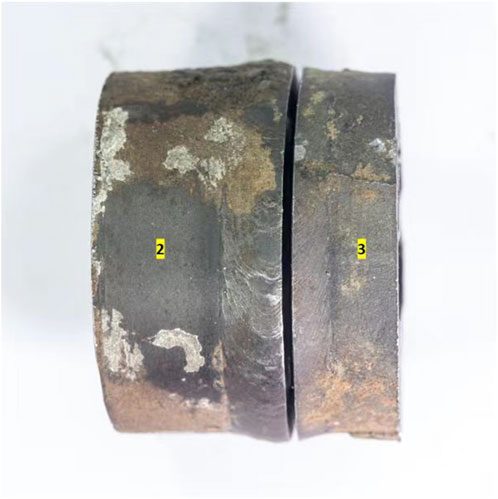
FIGURE 3. Macroscopic appearance of the surface at the failure location.
The fracture surfaces of samples No. 2 and No. 3 were observed on the same plane. To facilitate description, the fracture surface and the valve operating rod were designated as 0 o’clock, as depicted in Figure 4. The fracture was examined using a low-magnification stereomicroscope (Stemi 508, ZEISS, Germany). Fracture at 0 o’clock reveals a smooth and flat fracture surface at this location, exhibiting characteristics consistent with fatigue crack propagation. The fracture morphology at 6 o’clock shows many fatigue steps and radial stripes diverging from the inside of the fracture surface to the outside. These features primarily arise from the stress changes that occur as the fatigue crack extends to this point, leading to the expansion of the fatigue crack and the formation of multiple fatigue steps, visually represented as multiple radial stripes. This macroscopic appearance corresponds to the typical features of a fatigue crack source area.
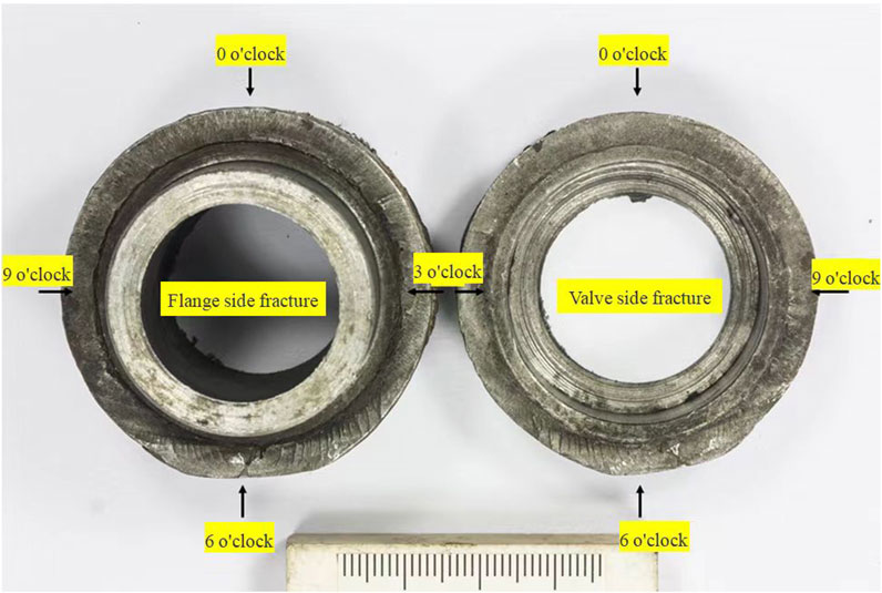
FIGURE 4. Macroscopic appearance of the fracture.
As can be seen from the fracture on the left side of Figure 4, the divergent radial stripes are mainly concentrated in the directions from 4 o’clock to 7 o’clock and from 11 o’clock to 2 o’clock on the figure, and it can be inferred that the fracture originated from multi-source fatigue cracking at these two places, and then extended to the whole valve fracture. The diameter of the valve is 50mm, so it can be calculated that the crack length from 4 o’clock to 7 o’clock is about 39.27mm, and the crack length from 11 o’clock to 2 o’clock is about 39.27 mm.
Based on the overall macro-morphology of the fracture, the suspected point of fracture initiation appears to be approximately at the 2 o’clock position. A closer examination of this area is presented in Figure 5. The image reveals machining tool marks on the surface of the valve body, indicating the presence of these marks from when the welding groove was machined. Furthermore, it is evident from the figure that the welding groove at this particular position did not fuse properly. Additionally, numerous fatigue steps were identified on the fracture surface, suggesting that the fatigue crack originated from the inner wall and propagated toward the outer wall. The depth of the unfused defect in the weld measures approximately 3.7 mm.
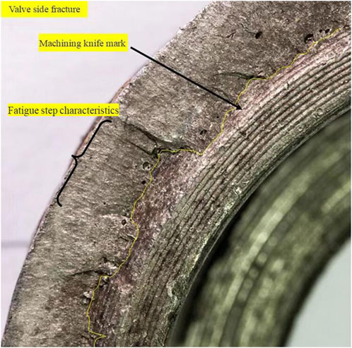
FIGURE 5. Macroscopic view of cracking location.
The crack initiation position depicted in Figure 5 was examined using a scanning electron microscope (EVO 10/AZteLiveOne30, ZEISS, Germany). The observations from this examination are presented in Figure 6. Figure 6 displays a micro-fracture where fatigue steps are visible, extending from right to left. Additionally, at the lower right position, multiple parallel stripe features are evident, which correspond to the machining tool marks left during sample processing. In the figure, the enlarged fracture surface appears smooth, without the presence of any other cracks.
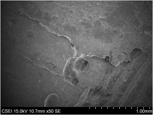
FIGURE 6. Microscopic fracture morphology of the cracking position.
A closer examination of the crack propagation position is illustrated in Figure 7. In the figures, it is apparent that the surface morphology of the fracture surface at the crack propagation position is smooth and devoid of any discernible grain characteristics. In Figure 7, the local fracture surface exhibits signs of contact with other objects.
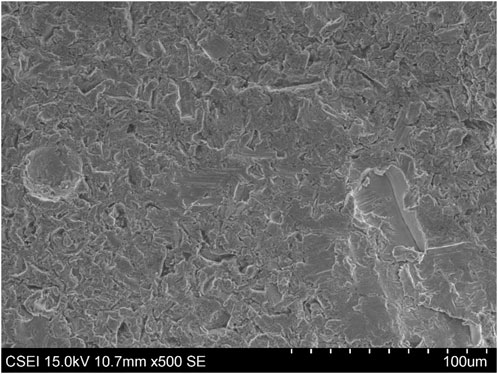
FIGURE 7. Fracture morphology at the location of stable crack extension.
Metallographic analysis was conducted on the weld sample from the non-cracked side of the valve body. The observation and analysis were performed using the AXIO Imager A2 m metallographic microscope (ZEISS, Germany). Figure 8 illustrates the location of the metallographic examination on sample No.5. Two key positions, namely, position 1 (at 0 o’clock) and position 2 (at 6 o’clock), were selected for observation. The metallographic photograph of position 1 is presented in Figure 9. It is evident from the figure that this position corresponds to a weld, specifically the weld joining the flange and the valve body. However, the root of this weld does not form a complete connection between the flange and the valve body, indicating a lack of penetration in the weld. The fusion line between the valve body and the weld was further magnified, revealing unfused defects along the fusion line between the weld and the valve body, consistent with the morphology shown in Figure 5 of the macro photograph of the fracture. It can be observed that there are also unfused defects on the flange side, although the length of these defects is smaller compared to those on the valve body side.
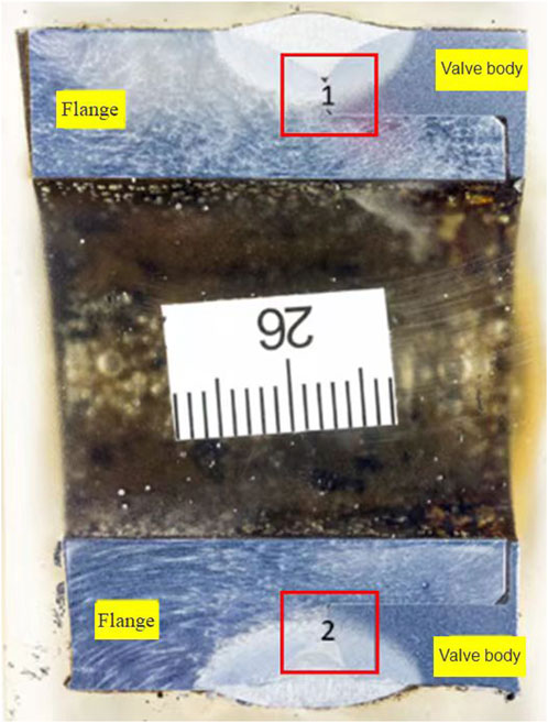
FIGURE 8. Metallographic test of specimen No. 5.
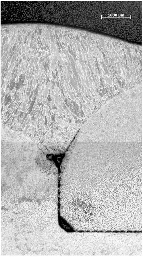
FIGURE 9. No. 5 specimen 0 o’clock position metallographic.
Figure 10 displays the metallographic image of position 2. From the macroscopic morphology, it is evident that this position corresponds to the welding arc-closing and arc-starting point. Consequently, multiple welding features are visible, along with unfused interlayer characteristics within the weld. By zooming in on the region between the valve body and the flange, it becomes apparent that a lack of penetration defect is present. Moreover, this lack of penetration defect exhibits the characteristic of extending toward the weld position.
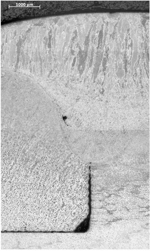
FIGURE 10. No. 5 specimen 6 o’clock metallographic image.
The cracked fracture was reassembled, and a metallographic examination of the cross-section was conducted. Figure 11 presents the metallographic specimen of the section at the crack initiation point. Key area 3 was selected for magnified observation, as shown in Figure 12. The figure reveals the presence of an unfused groove defect on the flange side within this area. The crack propagates from the unfused groove defect toward the outer wall, following a straight path without any bifurcation. Cross-section metallography was performed at the 0 o’clock and 6 o’clock positions of the failed weld. Figure 13 illustrates the sampling positions. A partial enlargement at the 0 o’clock position is depicted in Figure 14. It can be observed that only one weld is utilized in this area, exhibiting an incomplete penetration defect on the inner side of the weld. The crack, overall, is flat, straight, and devoid of any bifurcation or secondary cracks. From the figure, it is apparent that a lack of penetration defect is also present in the weld. Furthermore, there is a lack of fusion defect in the groove on the valve body side. The characteristics of the crack align with the fatigue characteristics of multi-point initiation from the inner wall position.
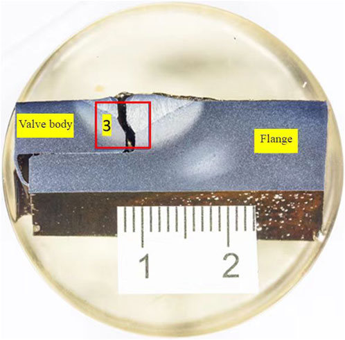
FIGURE 11. Cross-sectional metallography of the cracking point.
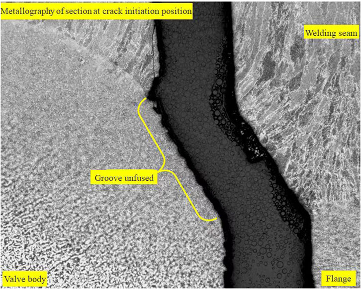
FIGURE 12. Local enlargement of cross-sectional metallography at the cracking point.

FIGURE 13. Failure weld 0 o’clock position and 6 o’clock position cross-sectional metallography.
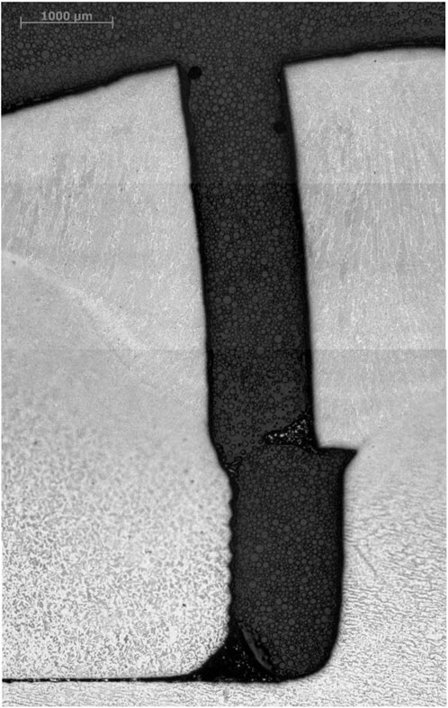
FIGURE 14. Failure weld 0 o’clock location cross-sectional metallographic image.
A Vickers hardness tester (FALCON 600, INNOVATEST Co., Netherlands) was used to assess the Vickers hardness of sample No.5. The test outcomes are presented in Table 1. The results indicate that the average hardness of the weld is 203, with no abnormalities observed. The valve body exhibits a hardness of 150, while the flange has a hardness of 172. These hardness test results fall within the normal range.
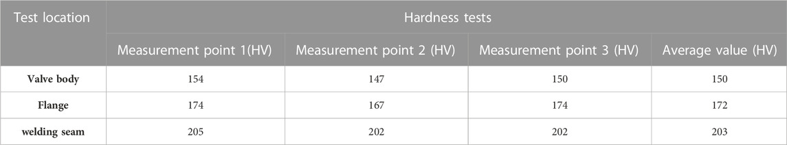
TABLE 1. Results of hardness measurement.
The chemical composition analysis of the valve body was conducted using the SPECTROMAXx photoelectric direct reading spectrometer (Spike Analytical Instruments Co., Germany). The test results are shown in Table 2. The test results demonstrate that the chemical composition of the valve body aligns with the composition requirements of ASME SA105/SA105M-2014.
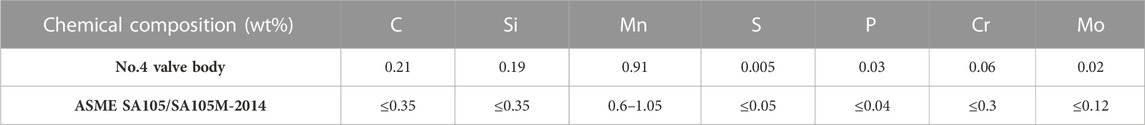
TABLE 2. Chemical composition of valve body.
Based on the fracture morphology, it is evident that the crack originated from a stress concentration site resulting from incomplete fusion and penetration during welding. Subsequently, the crack propagated along the weld toward the outer wall until leakage and detachment occurred. The position of crack initiation is biased toward the valve body side of the weld, which is associated with the defect of incomplete fusion in the valve body groove. Both macroscopic and microscopic examination of the fracture surface reveals a flush, non-bifurcated morphology without secondary cracks. These fracture surface characteristics do not align with the features of hydrogen embrittlement (Louthan, 2008; Djukic et al., 2015; Djukic et al., 2016). Furthermore, the weld hardness is normal, which preliminarily excludes weld damage caused by hydrogen embrittlement. Additionally, clear fatigue steps and radial stripes are visible through macroscopic and microscopic observation, indicating fatigue cracking. These findings align with the surface characteristics of fatigue cracking.
During compressor operation, the reciprocating motion induces vibration in the buffer tank and causes internal pressure fluctuations, creating a fatigue working condition. At the root of the weld joint between the shower valve connected to the buffer tank and the flange, a complete circle of incomplete penetration defects is present. Furthermore, a groove with an incomplete fusion defect is found in a local position of the valve body, indicating a significant welding defect. These incomplete penetration and incomplete fusion defects have sharp geometric shapes, leading to severe stress concentration at these geometric discontinuities. Consequently, under cyclic external loads, the guide valve becomes a source of fatigue cracks (Alencar et al., 2019; Shao et al., 2019; Wang DQQ. et al., 2021). Metallographic observation reveals that the incomplete penetration defect propagates into the weld under fatigue conditions. Additionally, the weld seam between the valve body and the flanges on both sides is a single-pass weld, greatly reducing the fatigue life of the entire component.
In general, for the fatigue life of a structure, the time required for the crack initiation stage accounts for more than 90% of the total fatigue crack life. Therefore, in fatigue analysis, the focus lies on crack initiation, and in the case of valve fatigue failure, the initiation position lies within the welding defect area, such as incomplete penetration and incomplete fusion in the weld, indicating a multi-source fatigue crack. The presence of welding defects results in premature fatigue failure of the structure.
Through macroscopic observation, it can be seen that there are obvious fatigue steps and radioactive stripes on the fracture surface, and at the same time, it can be observed that the tool marks left by the valve body welding beveling machine and obvious unfused defects. Through measurement, the height of unfused defects is 3.7 mm, and combined with the metallographic examination results, it can be seen that there are unfused defects in both welding joints connecting the valve and the flange. Based on the test results, the cause of failure for the weld between the valve body and the upstream flange is fatigue failure, with the fatigue crack initiating from the unfused defect near the inner wall. The sources of load that contribute to the fatigue failure of the weld are the vibrations resulting from the compressor operation and the pressure fluctuations of the medium on one side of the valve.
The substandard welding quality of the valve weld is a significant factor leading to premature fatigue failure. Both welds between the valve body and the flanges on both sides are single-pass welds, commonly exhibiting defects such as incomplete penetration and incomplete fusion. These defects possess sharp geometric shapes, leading to evident stress concentration and significant damage.
It is recommended to conduct periodic inspections of all welds and geometric discontinuities around the compressor, promptly addressing any cracks discovered. Additionally, a thorough investigation of valve welds from the same manufacturer using ultrasonic and X-ray testing confirmed the absence of severe welding defects.
For equipment in petrochemical plants and their peripheral components subject to alternating working conditions and vibration fatigue, it is advisable to clearly define relevant design requirements for fatigue working conditions in the design documentation. During manufacturing and installation, it is crucial to enhance inspection and testing protocols for equipment and parts exposed to fatigue conditions, thereby preventing the occurrence of associated welding defects. During plant shutdown inspections, an appropriate increase in surface inspections can be implemented for equipment experiencing fatigue conditions to reduce operational safety risks.
The original contributions presented in the study are included in the article/Supplementary material, further inquiries can be directed to the corresponding authors.
CD: Writing–original draft, Writing–review and editing. CL: Writing–review and editing. XL: Writing–original draft. JL: Writing–original draft. JY: Writing–review and editing. BL: Writing–review and editing.
The author(s) declare that no financial support was received for the research, authorship, and/or publication of this article.
The authors declare that the research was conducted in the absence of any commercial or financial relationships that could be construed as a potential conflict of interest.
All claims expressed in this article are solely those of the authors and do not necessarily represent those of their affiliated organizations, or those of the publisher, the editors and the reviewers. Any product that may be evaluated in this article, or claim that may be made by its manufacturer, is not guaranteed or endorsed by the publisher.
Alencar, G., de Jesus, A., da Silva, J. G. S., and Calcada, R. (2019). Fatigue cracking of welded railway bridges: a review. Eng. Fail Anal. 104, 154–176. doi:10.1016/j.engfailanal.2019.05.037
Braithwaite, F. (1854). On the fatigue and consequent fracture of metals. Minutes Proc. Inst. Civ. Eng. 13 (1854), 463–467. doi:10.1680/imotp.1854.23960
Chen, X., Wang, B., Guan, W., and Hu, M. (2001). Analysis of the current situation and defects in the use of pressure vessels and pipelines in petrochemical enterprises in China and countermeasures for failure prevention. Press Vessels 18 (5), 43–53. doi:10.3969/j.issn.1001-4837.2001.05.013
Djukic, M. B., Bakic, G. M., Zeravcic, V. S., Sedmak, A., and Rajicic, B. (2016). Hydrogen embrittlement of industrial components: prediction, prevention, and models. Corrosion 72 (7), 943–961. doi:10.5006/1958
Djukic, M. B., Zeravcic, V. S., Bakic, G. M., Sedmak, A., and Rajicic, B. (2015). Hydrogen damage of steels: a case study and hydrogen embrittlement model. Eng. Fail Anal. 58, 485–498. doi:10.1016/j.engfailanal.2015.05.017
Ge, Z., Lei, C., Wei, L., and Chai, D. (2021). “Fatigue life analysis of the pump head of silent reciprocating piston air compressor,” in 2021 3rd Asia Energy and Electrical Engineering Symposium (AEEES), Chengdu, China, 26-29 March 2021.
Jiang, Y. (2011). Research on damping technology and fatigue life analysis of the piping system of petrochemical equipment. Beijing: Beijing University of Chemical Technology.
Louthan, M. R. (2008). Hydrogen embrittlement of metals: a primer for the failure analyst. J. Fail Anal. Prev. 8, 289–307. doi:10.1007/s11668-008-9133-x
Lu, Y., Wei, Y., Wei, A., Liu, B., Gan, L., and Wang, Y. (2022). Analysis of failure causes of coke towers and research progress of life extension technology. J. Chang. Univ. Nat. Sci. Ed. 34 (2), 1–7. doi:10.3969/j.issn.2095-0411.2022.02.001
Lv, Y., Chen, X., Gao, J., Fan, Z., and Yang, Q. (2013). Research on the failure situation of large process compressors and failure prevention countermeasures in China. Fluid Mach. 41 (1), 14–20. doi:10.3969/j.issn.1005-0329.2013.01.004
Murakami, Y. (2003). “High and ultrahigh cycle fatigue,” in Comprehensive structural integrity. Editors I. Milne, R. O. Ritchie, and B. Karihaloo (Oxford: Pergamon), 41–76.
Nishida, S.-I. (1992). Failure analysis in engineering applications. Oxford, UK: Butterworth Heinemann.
Shao, C., Cui, H., Lu, F., and Li, Z. (2019). Quantitative relationship between weld defect characteristic and fatigue crack initiation life for high-cycle fatigue property. Int. J. Fatigue 123, 238–247. doi:10.1016/j.ijfatigue.2019.02.028
Wang, D. Q. Q., Yao, D. D., Gao, Z. B., Wang, Q., Zhang, Z. F., and Li, X. W. (2021b). Fatigue mechanism of medium-carbon steel welded joint: competitive impacts of various defects. Int. J. Fatigue 151, 106363. doi:10.1016/j.ijfatigue.2021.106363
Wang, Y., Tian, J., Yan, Z., Shu, X., He, Y., and Wang, L. (2021a). Analysis of the cracking failure of the new hydrogen compressor buffer tank outlet short joint in the hydrogen production plant. Liaoning Chem. Ind. 50 (3), 343–345. doi:10.3969/j.issn.1004-0935.2021.03.020
Wei, W., and Zhong, X. (2023). Leakage analysis and treatment of dry gas compressor inlet buffer tank receiver weld. Liaoning Chem. Ind. 52 (1), 51–55. doi:10.3969/j.issn.1004-0935.2023.01.013
Yang, W., Tian, F., Zhang, L., and Li, G. (2021). Analysis and treatment of cracks in hydrogen adsorption towers for variable pressure adsorption. Fine Spec. Chem. 29 (2), 33–36. doi:10.19482/j.cn11-3237.2021.02.08
Zerbst, U., Madia, M., Klinger, C., Bettge, D., and Murakami, Y. (2019a). Defects as a root cause of fatigue failure of metallic components. I: basic aspects. Eng. Fail Anal. 97, 777–792. doi:10.1016/j.engfailanal.2019.01.055
Zerbst, U., Madia, M., Klinger, C., Bettge, D., and Murakami, Y. (2019b). Defects as a root cause of fatigue failure of metallic components. II: non-metallic inclusions. Eng. Fail Anal. 98, 228–239. doi:10.1016/j.engfailanal.2019.01.054
Keywords: diesel hydrogenation unit, buffer tank, guide shower valve, fatigue cracking, welding defects, nondestructive examination
Citation: Du C, Liu C, Li X, Lu J, Yuan J and Liu B (2023) Fatigue fracture failure analysis of guide valve based on welding defects. Front. Mater. 10:1298138. doi: 10.3389/fmats.2023.1298138
Received: 21 September 2023; Accepted: 13 November 2023;
Published: 22 November 2023.
Edited by:
Tadeusz Hryniewicz, Koszalin University of Technology, PolandReviewed by:
Michał Böhm, Opole University of Technology, PolandCopyright © 2023 Du, Liu, Li, Lu, Yuan and Liu. This is an open-access article distributed under the terms of the Creative Commons Attribution License (CC BY). The use, distribution or reproduction in other forums is permitted, provided the original author(s) and the copyright owner(s) are credited and that the original publication in this journal is cited, in accordance with accepted academic practice. No use, distribution or reproduction is permitted which does not comply with these terms.
*Correspondence: Chenyang Du, Y2hlbnlhbmdkdUAxMjYuY29t; Xiaowei Li, bGl4aWFvd2VpY2dAMTYzLmNvbQ==
Disclaimer: All claims expressed in this article are solely those of the authors and do not necessarily represent those of their affiliated organizations, or those of the publisher, the editors and the reviewers. Any product that may be evaluated in this article or claim that may be made by its manufacturer is not guaranteed or endorsed by the publisher.
Research integrity at Frontiers
Learn more about the work of our research integrity team to safeguard the quality of each article we publish.