 Zhengxin Cao
 Renming Yang*
- School of Information Science and Electrical Engineering, Shandong Jiaotong University, Jinan, China
Vibration energy, as a sustainable energy source, has been widely studied. However, due to the low-frequency and randomness of vibration energy, it is difficult to collect vibration energy. Therefore, how to efficiently collect vibration energy is a very challenging task. In order to expand the working bandwidth of vibration energy collection under low frequency vibration excitation, improve the energy collection efficiency with random vibration excitation, this paper studies a piezoelectric-magnetic liquid composite energy collector problem by constructing a multi-frequency cantilever structure. First, we give some theoretical analysis for the designed novel composite energy collection, and then, by several experiment results, the paper further shows the validity and advantage of the collection. Different from existing literature on the issue, combining the advantages of piezoelectric materials (piezoelectric film) and magnetic liquid, the method of the present paper not only greatly expands the working bandwidth of the vibration energy collection, but also significantly improves the energy collection efficiency. The experimental results show that the device possesses the capability of resonant energy collection in the low-frequency range (5Hz–25 Hz), and can also operate effectively across the entire frequency band. Within the frequency sweep range of 5Hz–25Hz, the highest open-circuit voltage of the energy collection device can reach 21.7V, the highest instantaneous power can reach 171.61
1 Introduction
Vibration, as a recyclable energy that exists widely in nature, has attracted the attention of scholars in recent years. These vibration energy sources are endless and collected in many scenarios, such as road traffic (Wang et al., 2018a; Sun et al., 2018; Gholikhani et al., 2019; Gholikhani et al., 2020), water flow (Fang et al., 2017; Xu et al., 2018; Sun et al., 2019a), wind (Lin et al., 2019; Wang et al., 2020a; Sun et al., 2020), ocean waves (Zhang et al., 2021; Shi et al., 2022; Xu et al., 2023), and people’s walking (Kuang et al., 2017; Wang et al., 2017; Qian et al., 2019), etc. In order to provide self-powered electrical energy to IoT (Internet of Things) devices (Yoon et al., 2018) (wireless sensor network nodes), environmental monitoring devices (Tian et al., 2020) (acceleration sensors, etc.), and medical devices implanted in the body (Hong et al., 2019; Lim et al., 2020; Chen et al., 2021) (insulin pumps, cardiac pacemakers, medical robots, etc.), scholars have proposed many different types of devices to collect these vibration energies.
At present, there are four main energy collection methods for vibration energy: electrostatic effect method (Wang and Hansen, 2014; Tao et al., 2015; Xu et al., 2016), frictional electricity (Wang et al., 2020b; Zhu et al., 2022) (friction nanogenerator), piezoelectric effect method (Sun et al., 2019b; Li et al., 2023; Yu et al., 2023) (Piezoelectric films, piezoelectric ceramics, etc.) and electromagnetic induction method (Tan et al., 2016; Wang et al., 2018b; Maharjan et al., 2019) (magnetic liquids, etc.). These energy collection methods are widely used to capture and convert vibration energy into useable electrical energy, so as to achieve the purpose of energy recovery and utilization. The electrostatic effect method utilizes the change of the distance between the electrostatic capacitance and the electrode during vibration motion to change the capacitance value, thereby generating the accumulation and flow of charges and achieving energy conversion. Using the electrostatic effect and the normalized power density method (Zhang et al., 2018), designed an electrostatic vibration energy collector. Its excellent comprehensive performance provides a broad application prospect for energy collection of random sources. Based on the uneven distribution of electrostatic charges brought by the frictional movement between materials, the triboelectrification vibration energy collection device forms a potential difference to realizes energy conversion. In (Xu et al., 2023), the authors studied an isotropic triboelectric-electromagnetic hybrid nanogenerator (iTEHG) based on guiding liquid to efficiently collect omnidirectional ocean wave energy. This design motivates the development of self-sufficient ocean sensors. Applying the characteristics of the piezoelectric material, the piezoelectric vibration energy collection device produces an unbalanced charge distribution when the material is vibrated, thereby generating voltage and realizing energy conversion. Based on the characteristics of piezoelectric materials (Deng et al., 2019), presented a multi-state vibration energy collection method. This method can achieve the maximum number of stable equilibrium states and provide a new design concept for nonlinear vibration energy collector. However, this energy collection method does not make full use of the structure characteristics, and only adds the permanent magnet at the end of the cantilever beam to make the device have the characteristics of synergistic multi-stable state. Therefore, the device has a low utilization rate of the space structure, low output and low conversion efficiency with a single energy conversion mechanism. The electromagnetic vibration energy collection device uses the magnetic field brought by the vibration movement to interact with the coil, thereby generating the induced electromotive force to realize energy conversion. By using the characteristics of electromagnetic induction (Yang et al., 2022), proposed a vibration energy collector to directly convert mechanical motion into electrical energy. However, since the device does not have multi-frequency synergy, its energy conversion efficiency and output power may vary greatly at different frequencies, which implies that it cannot adapt to multiple vibration environments at the same time. In addition, the less stable state of the device may also lead to poor energy conversion efficiency when the vibration energy is lower or higher, making it difficult to fully utilize the vibration energy in the environment.
In this paper, by improving the shortcomings and deficiencies of the multi-frequency cooperative multi-stable vibration method presented in (Deng et al., 2019) and the magnetic liquid device designed by (Yang et al., 2022), we propose a piezoelectric-magnetic liquid composite energy collector with a multi-frequency cantilever beam array structure. The energy collector can convert energy simultaneously by installing a magnetic liquid device at the end of the multi-frequency cantilever beam and the piezoelectric film at the root of the cantilever beam. The permanent magnets repel each other, so that the energy collection device realizes the comprehensive characteristics of multi-frequency coordination and multi-stable state. The main innovations of this paper are stated as follows: (1) Different from (Deng et al., 2019), this paper proposes an energy collector that replaces the permanent magnet by a magnetic liquid device. This design makes a cantilever beam not only generate electricity through piezoelectric films but also collect energy through the magnetic liquid device. (2) Unlike (Yang et al., 2022), the energy collector designed in this paper makes full use of a pair of permanent magnet structures of the magnetic liquid device. By utilizing the repulsion between the permanent magnets of the magnetic liquid devices, the vibration of each cantilever beam can influence several others. This not only widens the working bandwidth of energy collection but also enables the energy collector to have better performance of collecting energy at lower frequencies. (3) Based on the mechanism analysis for collection and conversion, and combing new rectifier and transform devices, we propose more effective collection structure and design method, which further expands the range and flexibility of energy collection.
2 Main results
This section mainly puts forward the design principle, experimental process and analysis of experimental results.
2.1 Design method and principle
Figure 1 shows the overall structure of the piezoelectric-magnetic liquid composite energy collector designed in this paper. The device is mainly divided into four parts: the first part is a plurality of cantilever beams with different frequencies, that is, 65 MN spring steels with different thicknesses are fixed on the main beam of vibration table. The cantilever beams with different thickness make the piezoelectric-magnetic liquid composite energy collector have multi-frequency characteristics. That is, the piezoelectric-magnetic liquid composite energy collector has multiple resonance frequencies in the low frequency range, which effectively broad the collection bandwidth. The second part is the connection device used to connect the cantilever beam and the magnetic liquid device. It guarantees the transmission efficiency of vibration and the integrity of magnetic field. The third part is the magnetic liquid device fixed at the end of the multi-frequency cantilever beams. The fourth part is to paste piezoelectric material (PVDF) on the root of the cantilever beam, its purpose is to use the vibration of the beam to drive the deformation of PVDF and generate electricity.
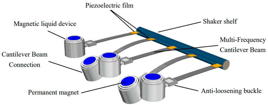
FIGURE 1. Overall structure of piezoelectric-magnetic liquid composite energy collector.
Remark 2.1. Materials of four components: 1) The cantilever beam material is 65mn spring steel. 2) The connection device material is resin material. 3) The main body of the magnetic liquid is resin material, and the surrounding area with a diameter of 0.4 mm insulation copper wire and the material of the upper and lower permanent magnets are made of iron and boron. 4) The voltage material is made of polytin fluoride.
The structure schematic diagram of a single cantilever beam unit is shown in Figure 2, including three parts of the cantilever beam connection device, the magnetic liquid device and the PVDF pasted on the cantilever beam. The connection device is a cylindrical hollow shape with the bottom extending 1 mm inwards for clamping the magnetic liquid device. While the magnetic liquid device has a cylindrical permanent magnet on the top and bottom respectively, which mainly provides an external magnetic field for the magnetic liquid device. In addition, the outer side of the inner cylinder of containing magnetic liquid is wrapped with 0.4 mm insulated copper wire, which is mainly to generate induced electromotive force in the coil when being vibrated. The lower part of the upper permanent magnet has the entrance for injecting the magnetic liquid. The magnetic liquid device is equipped with part of the liquid magnetic material. The main components of the liquid magnetic material are base carrier liquid (water), surfactant (oleic acid) and magnetic nanoparticles (ferric oxide, particle diameter of 10 nm). The thickness of the PVDF pasted on the cantilever beam is 52μm, and it is pasted on the root of the cantilever beam to achieve fast response speed, which can respond to the vibration of the cantilever beam in time.
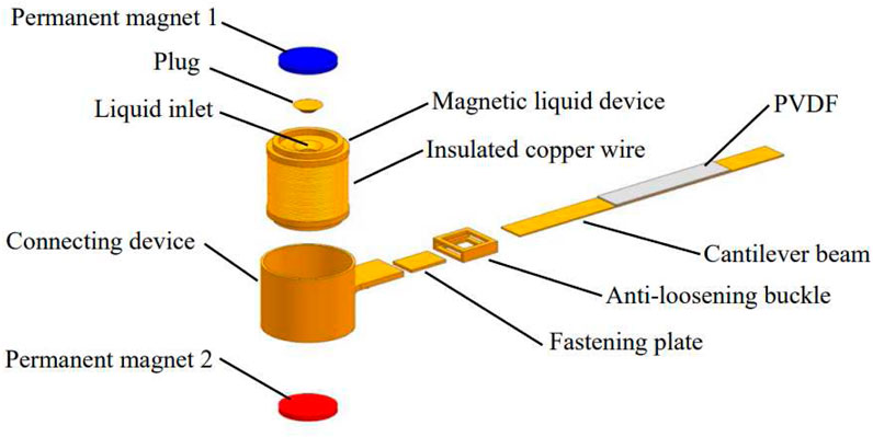
FIGURE 2. Structure schematic diagram of a single cantilever beam vibration unit.
Remark 2.2. Magnetic ore nano particles are purchased directly. In the Bisley New Materials (Suzhou) Co., Ltd., the diameter is 10 nm, and its purity is 99.95%.
The schematic diagram of the piezoelectric-magnetic liquid composite energy collector is shown in Figure 3, mainly composed of liquid magnetic material, connecting device, hollow cylindrical body with extensions at the top and bottom, insulated copper wire with a diameter of 0.4mm, two equally sized permanent magnets, cantilever beams with different thicknesses, and PVDF piezoelectric film. The working principle of the piezoelectric-magnetic liquid composite energy collector is to use the nonlinear coupling and cooperative multi-stable vibration between multiple different cantilever beam vibration units to realize broadband vibration energy collection. When the piezoelectric-magnetic liquid composite energy collector is excited by external vibration, the vibration excitation received by the cantilever beam with different thickness will first be transmitted to the PVDF pasted on the root of the cantilever beam, and the PVDF will generate electric energy after deformation. When the vibration excitation is transmitted to the magnetic liquid device, the sloshing liquid changes the magnetic flux in the magnetic liquid device, thereby generating an induced electromotive force in the insulated copper coil wound around the magnetic liquid device. When the vibration frequency reaches the natural frequency of the magnetic liquid, resonance occurs, and the induced electromotive force is maximized.
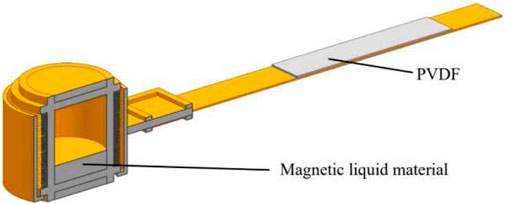
FIGURE 3. Composite energy collector schematic.
2.2 Properties of piezoelectric-magnetic fluid composite collecting
In the section, to the convenience of the experiment of the next section, we present some analysis on the piezoelectric-magnetic fluid composite cantilever and give specific data used in the paper.
2.2.1 Resonant characteristics of the same frequency
The design approach for same frequency resonance (Tien and DSouza, 2020) is based on deriving the inherent oscillation frequencies of each cantilever beam and the connected magnetic liquid. Once the external dimensions of the magnetic liquid device and the magnetic field strength of the permanent magnets 1 and 2 are determined, the inherent vibration frequency of the magnetic liquid can be modified by changing its density. This allows for achieving the phenomenon of same frequency resonance between the cantilever beams and the magnetic liquid in each vibrating unit. Since the piezoelectric thin film is adhered to the root of the cantilever beam, when the cantilever beam reaches resonance, the piezoelectric thin film also reaches resonance. The piezoelectric thin film and the magnetic liquid simultaneously achieve resonance, resulting in a greater amount of electrical energy generation at the same frequency. Finally, the rectified output of each vibrating unit’s PVDF (Polyvinylidene fluoride) is connected in series with the rectified output of the magnetic liquid device, and the outputs of the five vibrating units are connected in parallel to achieve the collection of vibrational energy. The specific analysis process is stated as follows:
The resonant frequency of each vibrating unit’s cantilever beam f1n, can be calculated via the following equation (Xiang and Mao, 2019):
Eq. 1 can be used to calculate the first resonant frequency f1n of each vibrating unit’s cantilever beam, where n = 3 represents the vibrating unit with a cantilever beam thickness of 0.3mm, n = 4 represents the vibrating unit with a cantilever beam thickness of 0.4mm, n = 5 represents the vibrating unit with a cantilever beam thickness of 0.5mm, and so on. Where, * is the product of two real numbers, E represents the elastic modulus of the cantilever beam, In is the moment of inertia of the cross-section for different vibrating units, and Meqn represents the equivalent mass for different vibrating units, L denotes the length of the cantilever beam.
Eq. 2 involves the width w and the thickness tn of the cantilever beam. In Eq. 3, ρ represents the material density of the 65Mn spring steel cantilever beam, and m is the weight of the magnetic liquid device.
Now, to facilitate analysis in the next section, we give specific parameter values to be used in the paper (See Table 1).
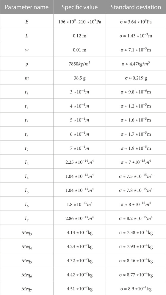
TABLE 1. Parameter values.
From the above and Eqs 1 and 2 3, one can obtain the first resonant frequencies of cantilever beams with different thicknesses 0.3mm, 0.4mm, 0.5mm, 0.6mm, 0.7 mm are approximately f13 = 1.83Hz, f14 = 2.78Hz, f15 = 3.85Hz, f16 = 5.01Hz, f17 = 6.24Hz, respectively.
Remark 2.3. These values are calculated based on the provided parameters and assumptions. However, since actual situations may be influenced by other factors such as the nonlinear properties of materials, the geometric shape of the cantilever beam, the method of fixation and the impact of the environment of the test bench, we only give several approximations in the section. Even so, the effectiveness of the results can be verified by a frequency sweep vibration experiment in Section 2.3.1 of the paper below.
Under the action of the external magnetic field of the permanent magnets 1 and 2, the inherent oscillation frequency of the magnetic liquid can be expressed as (Yang et al., 2022):
In Formula (4), the variables are defined as follows: g represents the gravity acceleration, χ is the magnetic susceptibility of the magnetic liquid, μ0 is the permeability of free space, ρn represents the density of the magnetic liquid in different vibrating units, ki is the wave number, h1 is the height of the magnetic liquid, B(z) is the magnetic induction intensity of the upper and lower permanent magnets in the normal direction,
Using Formula (1) and Formula (4), we can calculate the conditions for the same frequency resonance between the magnetic liquid and the cantilever beams in each vibrating unit. Specifically, calculating first resonant frequency based on Formula (1), letting f1n = wn, and using Formula (4), one can determine the density of the magnetic liquid that achieves simultaneous resonance with the cantilever beams of different vibrating units as follows:
Formula (5) allows us to calculate the resonant density that matches the cantilever beams of different vibrating units. According to the above data and Eq. 5, the specific density value of the magnetic liquid is given as the follows: ρ3 = 686.27 kg/m3, ρ4 = 691.93 kg/m3, ρ5 = 700.58 kg/m3, ρ6 = 713.68 kg/m3 and ρ7 = 732.35 kg/m3, respectively.
On this basis of studying the density of magnetic fluids, we also analysis the influence of an external magnetic field on the magnetic fluid. In a magnetic fluid, the applied magnetic field interacts with the magnetic particles or molecules, resulting in the generation of magnetic forces.
Formula F = VχH describes the magnetic force in the magnetic fluid, where F represents the magnetic force in the magnetic fluid, V represents the volume of the magnetic fluid, χ represents the magnetic susceptibility of the magnetic fluid, and H represents the magnetic field strength of the applied external magnetic field.
The external magnetic field intensity not only affects the magnetization strength of the magnetic fluid but also influences its viscosity. Therefore, changes in the external magnetic field intensity can have an impact on the oscillation behavior of the magnetic fluid. When the magnetic field intensity is high, it restricts the movement of the fluid inside the collector and the rotation of individual magnetic particles. Additionally, the increased viscosity of the magnetic fluid causes it to adhere to the inner wall of the collector, resulting in a decrease in the rate of magnetic flux change and subsequently reducing the electromotive force. As the magnetic field intensity gradually decreases, the amount of magnetic fluid adhering to the inner wall decreases, and the increased oscillation speed of the magnetic fluid leads to an increase in the rate of magnetic flux change. However, when the displacement distance exceeds a certain range, the weakening of the external magnetic field intensity reduces the magnetization strength of the magnetic fluid, resulting in a decrease in the electromotive force (Further details, please see Ref (Chen, 2022)).
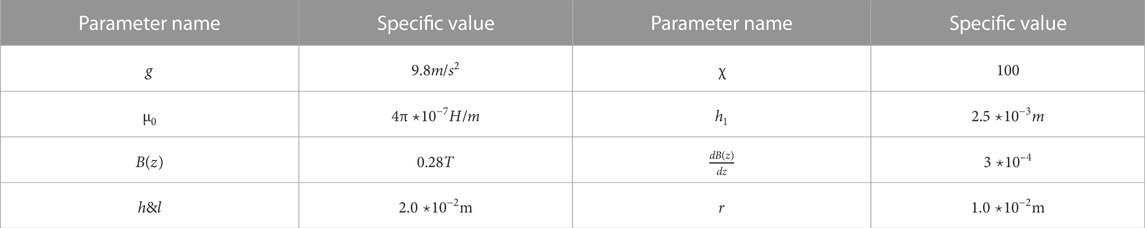
TABLE 2. Parameter values of Eq. 4.
2.2.2 Analysis of performance characteristics
The multi-frequency performance of the piezoelectric-magnetic liquid composite energy collector is reflected in the fact that the cantilever beam array is composed of cantilever beams with different thicknesses, so each cantilever beam will have a different resonant frequency. The theoretical analysis has been given in Subsection 2.2.1, and the experimental verification will also be carried out in Subsection 2.3.1.
The synergy is reflected in the fact that the end of each cantilever beam is equipped with a magnetic liquid device. The magnetic liquid device is equipped with a pair of permanent magnets. The permanent magnets repel each other, so that when one cantilever beam vibrates, several cantilever beams can be affected, thereby broadening the operating bandwidth of energy collection.
To analyze the magnetic interaction between the cantilever beams, we adopt the expression (Xiang and Mao, 2019) of vector differential method. As shown in Figure 4, magnetic dipoles α and β represent the permanent magnets on cantilever beams α and β, respectively (α, β ∈ {1, 2, ⋯, n}, α ≠ β). The magnetic moments of dipoles α and β are represented by
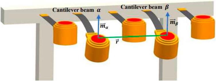
FIGURE 4. Magnetic interaction between different cantilever beams.
In Equation 6, μ0 represents the vacuum permeability (In the paper, μ0 = 4π*10−7H/m),
Through the analysis of magnetic interaction between cantilever beams using the vector differential method, it is determined that the magnetic field generated by dipole α at the position of dipole β is related to the gradient of the dipole moment
In terms of experimental validation, in Section 2.3.1, the 0.3 mm thick vibrating unit of the cantilever beam reaches second harmonic resonance between 20.5Hz and 24.5 Hz (See Figure 7A), and the open-circuit output voltage of the adjacent 0.4 mm thick vibrating unit at the same frequency range also increases (See Figure 7B). This validates the synergy of the system.
The multi-stability is reflected in that the energy collector uses the magnetic field force of the upper and lower permanent magnets in the magnetic liquid to make the motion of the vibration mechanism nonlinear. When the vibration system is subjected to the nonlinear force, the potential energy function will change, thus forming multiple potential energy wells. The vibration system produces multi-stable motion between these potential energy wells, which can significantly increase the response amplitude of the vibration mechanism, especially under non-resonant frequency excitation (Further details, please see (Deng et al., 2019)).
2.3 Frequency sweep vibration experiment
In order to verify the influence of the cooperative multi-stable state of the piezoelectric-magnetic liquid composite energy collector, the section designs a set of vibration sweep experiments.
In the following experiments, to simulate the low-frequency and low-intensity excitation of the real environment, the vibrating table is used to provide 5Hz–25 Hz sinusoidal sweep excitation for the experimental device, the sweep rate is 0.2 Hz/s, and the excitation amplitude is 2 mm. Under the vibration excitation, we measure the open-circuit output voltage, power and capacitive electric field energy of each cantilever vibration unit. The experimental setup consists of cantilever beams with identical PVDF piezoelectric films attached at their root, along with magnetic fluid devices of varying densities (density increases with cantilever thickness). The structural parameters of the experimental setup are provided in Table 3.
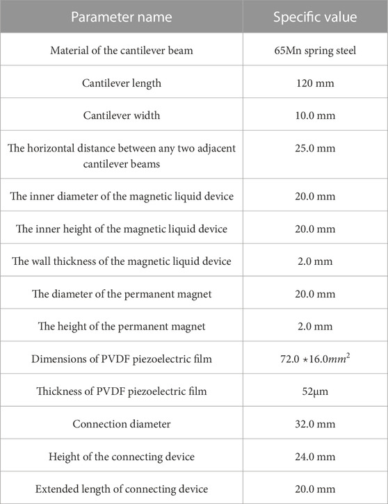
TABLE 3. Structural parameters of the experimental device.
The piezoelectric-magnetic liquid composite cantilever array is fixed on the top of the aluminum alloy frame. Use the DC-300-3 Su test shaker to provide vibration excitation for the experimental setup. Use a ZLG DMM6000 desktop multi-meter to record the output voltage of the device, and a 10MΩ load resistor as an external load. The experimental system is shown in Figure 5.
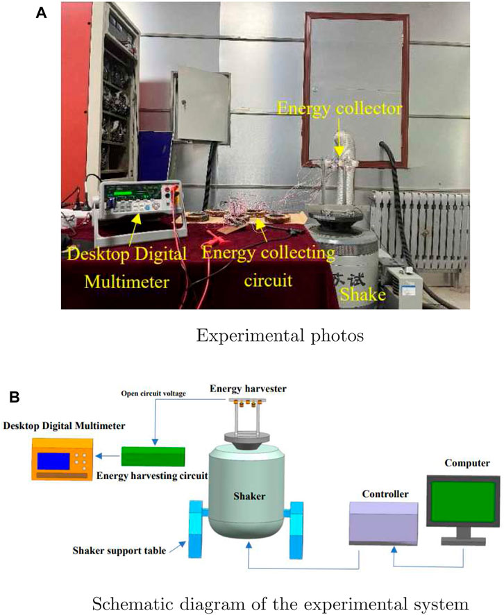
FIGURE 5. Vibration experiment system.
2.3.1 Open circuit voltage and broadband characteristics
In order to test the working frequency band and resonance of the piezoelectric-magnetic liquid composite energy collector, five cantilever beams with different thicknesses and natural frequencies are used to form an array in the following frequency sweep experiment, which ensure the relative displacement is constantly changing. With the unchanged excitation conditions of the frequency sweep experiment, the experimental setup is shown in Figure 6. The thicknesses of the five beams in the piezoelectric-magnetic liquid composite cantilever array are 0.3 mm, 0.4 mm, 0.5 mm, 0.6 mm, and 0.7 mm, respectively, and the cantilever beams in the array are arranged in order of thickness from thin to thick.
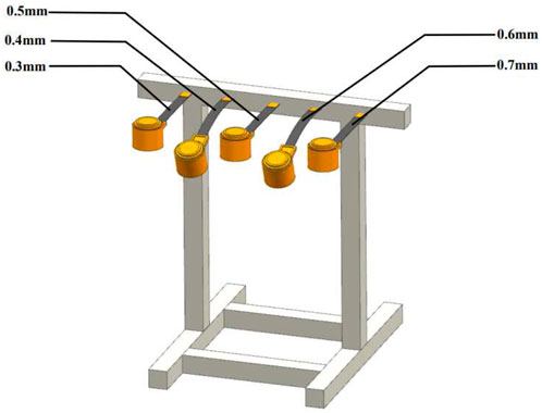
FIGURE 6. Piezoelectric-magnetic liquid composite cantilever array.
In order to study the widening effect of the vibration energy collector, the open-circuit output voltage of each cantilever vibration unit is measured using a desktop digital multi-meter under external frequency sweep excitation and is shown in Figure 7 respectively. The frequency band whose open circuit voltage is greater than 4 V is selected as the effective working frequency band (Note: The reason of choosing 4 V is that the general sensor equipment is powered by 3 V. Thus, to show the collection capacity more effectively and intuitively, the paper chooses 4 V as the effective working frequency band). Correspondingly, the effective working frequency band is marked as a beige area in Figure 7.
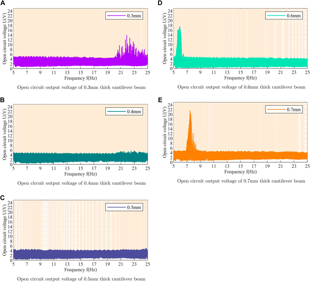
FIGURE 7. The open-circuit output voltage of each cantilever array.
From Figure 7A, it is easy to see that the area of collect energy almost across the entire frequency range with a voltage output of over 4 V. In other words, the effective working frequency band has been widened. The reason why the 0.3 mm-thick cantilever beam does not reach resonance in the low frequency state is that the minimum vibration frequency of the vibration platform is 5 Hz. Therefore, the resonant point between 0 and 5 Hz cannot be displayed, resulting in only the second harmonic frequency of the 0.3 mm-thick cantilever beam being shown in Figure 7A (Note: f13 ≈ 1.83Hz). Figure 7 (b) and (c) indicate that the effective working range is no longer limited to the resonance frequency of the cantilever beam. The reason why the 0.4mm and 0.5 mm thick cantilever beams does not reach resonance between 5 and 25 Hz is that their first resonant frequency is below 5 Hz. Due to the minimum vibration frequency of the vibration table being 5Hz, the resonant points between 0 and 5 Hz cannot be displayed in Figures 7B,C (Note: f14 ≈ 2.78Hz and f15 ≈ 3.85Hz). This proves the low-frequency characteristics of the piezoelectric-magnetic fluid composite cantilever beam array. As shown in Figure 7D, the maximum open circuit output voltage is only generated at 5.9Hz, reaching 17.6V, and the resonance occurs from 5.2 Hz to 6.2Hz, lasting for 5 seconds. Figure 7D shows that the effective working frequency band of the 0.6 mm thickness cantilever beam becomes increasingly unstable after 18.9Hz, validating the strong performance of the piezoelectric-magnetic liquid composite energy collector in the low frequency range. As shown in Figure 7E, the maximum open circuit output voltage is 21.7 V at 7.4Hz, and there are a total of five resonances during the sweep reaching the highest open circuit output voltage 21.7V, 12.2V, 8.51V, 7.47V and 5.6 V with 7.4Hz, 7.9Hz, 8.1Hz, 8.3 Hz and 8.4Hz, respectively. It is worth noting that all of these five resonant frequencies are within 10Hz, which demonstrates the efficiency of the piezoelectric-magnetic liquid composite energy collector in the low-frequency range. These experimental results show that the piezoelectric-magnetic liquid composite cantilever beam array has outstanding advantages in low-frequency vibration energy collecting.
Thanks to the synergistic multi-stable motion of the cantilever array and the low-frequency characteristics of the magnetic liquid device, the five cantilevers can be mutually driven during the vibration process. The experimental phenomena mentioned above further explain the reason why the output voltage of the five cantilevers increases under non-resonant frequency excitation. The synergistic multi-stable motion significantly enhances the response amplitude and output voltage of the multi-frequency structure under non-resonant frequency excitation, and endows the vibration energy collector with better broadband characteristics.
2.3.2 Output power
The broadening of the working frequency band of the energy collector is reflected in not only the open-circuit output voltage, but also the output power. In order to study the influence of the cooperative multi-stable motion on the output power, under the same experimental conditions, the piezoelectric-magnetic liquid composite cantilever array is subjected to sweep excitation experiments. Applying the formula
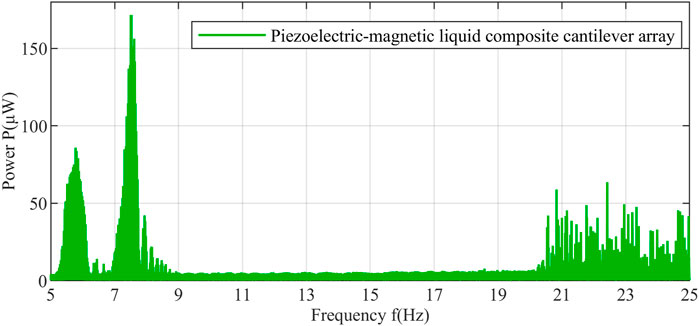
FIGURE 8. Output power of piezoelectric-magnetic liquid composite cantilever array.
It can be seen from Figure 8 that, when the excitation frequencies are 5.78 Hz, 6.44 Hz, 7.52 Hz, 7.93 Hz, 8.15 Hz and 8.34 Hz, the maximum instantaneous power reach 89.53μW, 14.06μW, 171.61μW, 42.12μW, 22μW and 14.44 μW respectively. At the same time, under vibration excitation, the five cantilever beam vibration units also reach resonance between 20.24 Hz and 25Hz, and the maximum instantaneous power reach 63.52 μW. The above experimental results show that the piezoelectric-magnetic liquid composite energy collector effectively improves the output power at low frequencies.
2.3.3 Capacitor charging experiment
In order to further study the energy collecting efficiency of the piezoelectric-magnetic liquid composite energy collector, a capacitive charging experiment is carried out. The experiment still adopts sinusoidal frequency sweep excitation, and the excitation conditions remain unchanged. In the piezoelectric-magnetic liquid composite cantilever beam array, the magnetic liquid device of each cantilever beam vibration unit is boosted (transformer), and the boosted magnetic liquid device is rectified, and the piezoelectric film is also rectified at the same time. The output of the magnetic liquid device and the piezoelectric film is rectified and then connected in series, and finally the output of the five cantilever beams is connected in parallel to both ends of a capacitor. The circuit diagram of a single vibration unit is shown in Figure 9. During the vibration process, the capacitor voltage U is recorded using a desktop digital multi-meter. The capacitor used in the experiment is a 470 μF electrolytic capacitor. The change curve of the electric field energy
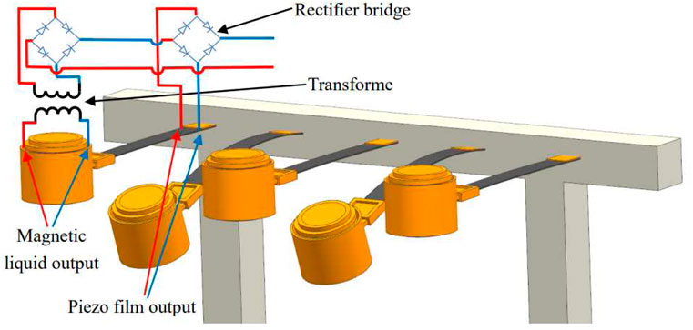
FIGURE 9. Circuit diagram of a single vibration unit.
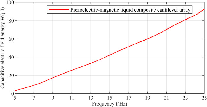
FIGURE 10. Electric field energy variation curve during capacitor charging.
During the whole frequency sweep process, the charging curve has a larger slope, so it has a faster charging rate and a higher output power. After being subjected to a 100-s vibration excitation with a sweeping frequency, the energy collected by the piezoelectric-magnetic liquid composite cantilever beam array reaches 92.39 μJ. It is mainly benefit from the cooperative multi-stable motion of piezoelectric-magnetic liquid composite cantilever arrays. Therefore, this piezoelectric-magnetic liquid composite cantilever array not only broadens the working frequency band of the vibration energy collector, but also improves the energy collection efficiency.
2.4 Vibration experiments in actual application scenarios
In order to further validate the energy collecting performance of the piezoelectric-magnetic fluid composite collector at low frequencies, a comparative vibration experiment is conducted using a set of cooperative multi-stable cantilever beams in contrast to the piezoelectric-magnetic fluid composite cantilever beams. The cooperative multi-stable cantilever beam array contains five beams, which have the same material, length, and width. The difference is that the free end of the cooperative multi-stable cantilever beams is connected to a permanent magnet, while the free end of the piezoelectric-magnetic fluid composite cantilever beams is attached to the magnetic fluid device of the equal mass. All the cantilever beams are attached with the same PVDF piezoelectric film at their roots. The structural parameters of the experimental setup are provided in Table 4.
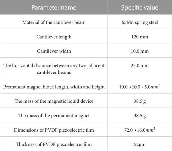
TABLE 4. Structural parameters of comparative experimental devices.
The cooperative multi-stable cantilever beam array and the piezoelectric-magnetic fluid composite cantilever beam array are both fixed on the top surface of an aluminum alloy frame. An MS90A treadmill is used to provide vibration excitation for the experimental setup. The open circuit voltage and output power and capacitor charging experiments are performed at an operating speed of 5 km/h, which corresponds to approximately 1.39 m/s. For each step taken during running, a stride length is 0.8 m, resulting in a step frequency of approximately 1.74 Hz. The output voltage of the devices is recorded using the ZLG DMM6000 desktop multi-meter, and a 10MΩ load resistor is used as the external load. The experimental setup is shown in Figure 11.
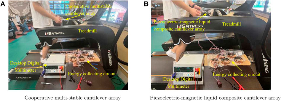
FIGURE 11. Treadmill vibration test system.
2.4.1 Comparison results of open circuit output voltage
In the subsequent comparative experiment, the excitation condition for the comparative experiment is a running machine with a speed of 5 km/h, and the experimental setup is depicted in Figure 12. The thicknesses of the five beams in the piezoelectric-magnetic fluid composite beam array are 0.3 mm, 0.4 mm, 0.5 mm, 0.6 mm, and 0.7 mm, respectively, which are the same as ones in the cooperative multi-stable cantilever beam array. The masses of the magnetic fluid device at the end of the piezoelectric-magnetic fluid composite beam array are equivalent to the ones of the permanent magnet block at the end of the cooperative multi-stable cantilever beam array. The thickness of cantilever beams are arranged from thin to thick.
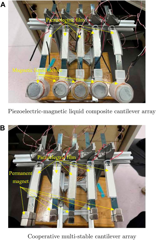
FIGURE 12. Comparative experimental.
In order to study the widening effect of the vibration energy collector in the real environment, we measure and record the open-circuit output voltage on a parallel combination of five cantilever beam vibration units. The results are plotted in Figure 13. The portions of the piezoelectric-magnetic fluid composite cantilever beam array’s open-circuit output voltage is greater than that of the cooperative multi-stable cantilever beam array are highlighted in a beige-colored region in Figure 13.
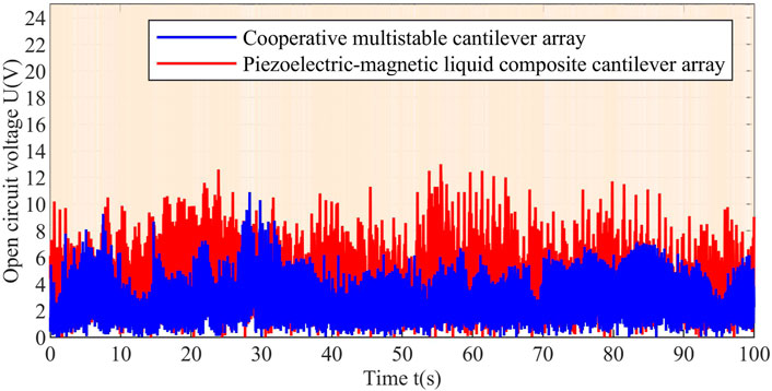
FIGURE 13. Comparative experiment of open circuit output voltage (low frequency vibration frequency: 1.74 Hz).
As shown in Figure 13, compared to that of the cooperative multi-stable cantilever beam array, the operating bandwidth of the piezoelectric-magnetic fluid composite cantilever beam array’s open-circuit output voltage is enhanced by 296.43%. Among the 50,000 collected data points, the open-circuit output voltage values of 39,920 data points in the present paper are higher than ones in (Deng et al., 2019). Additionally, from Figure 13, it can be observed that the open-circuit output voltage of the collecting device in the present paper is mostly concentrated between 3 V and 6V, while the open-circuit output voltage of designing energy collector in (Deng et al., 2019) is concentrated between 1V and 3 V. These experimental results demonstrate the advantages in low-frequency vibration energy collecting by applying the device of the present paper.
2.4.2 Experimental comparison of output power
The low-frequency characteristics of the energy collector is not only reflect in the open-circuit output voltage but also in the output power. To study the effect of cooperative multi-stable motion on the output power, a comparison is made between the cooperative multi-stable cantilever beam array and the piezoelectric-magnetic fluid composite cantilever beam array under the same external excitation. The experimental conditions remained unchanged. The power delivered by the energy collector to the external load is calculated by using the formula

FIGURE 14. Output power comparison experiment.
Among them, the frequency bands where the output power of the piezoelectric-magnetic fluid composite cantilever beam array exceeds that of the cooperative multi-stable cantilever beam array are marked as the light-yellow region. From Figure 14, it can be observed that, in the majority of the frequency range, the output power of the piezoelectric-magnetic fluid composite cantilever beam array is higher than that of the cooperative multi-stable cantilever beam array. For example, at vibration times of 37.0s, 61.5s, 75.7s, and 80.9s, the maximum instantaneous power outputs of piezo-magnetic liquid composite cantilever array achieve 3.49μW, 3.34μW, 3.86μW, and 4.42μW, respectively. In contrast, the co-oscillating multi-stable cantilever array only produces power outputs of 0.84μW, 0.33μW, 1.09μW, and 0.9 μW at the corresponding times. Compared to the cooperative multi-stable cantilever beam array, the output power of the piezoelectric-magnetic fluid composite cantilever beam array is increased by 415%, 1,012%, 354%, and 491%, respectively. Furthermore, the output power bandwidth of the piezo-magnetic liquid composite cantilever array is increased by 152.61% compared to the output power bandwidth of the synergistic multi-stable cantilever array. Among the 50,000 data points collected, 30,207 data points in this paper have higher output power values than the one in (Deng et al., 2019). These experimental results demonstrate the effective enhancement in the output power of the energy collector for low frequencies.
2.4.3 Capacitor charging experiment comparison
In order to further show the influence of vibration frequency and amplitude in real environments, under the same conditions, we also give a comparison result in terms of the charging rate of capacitors. During the vibration process, the voltage across the capacitor, denoted as U, is recorded using a desktop digital multi-meter. In the cooperative multi-stable cantilever beam array, the rectification process is applied to the piezoelectric films, and the rectified outputs of the five cantilever beams are also connected in parallel to the terminals of another capacitor. Two electrolytic capacitors with a capacitance of 47 μF are used in the experiment. The variation curves of the stored electrical energy in the two capacitors
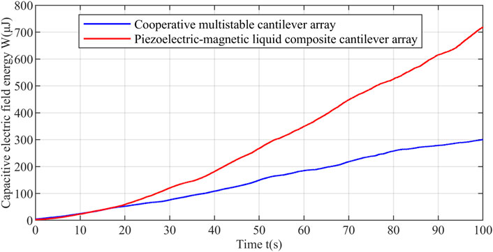
FIGURE 15. Comparison experiment of 47 μF electrolytic capacitor charging.
Throughout the experiment, the energy stored in the capacitance connected to the piezoelectric-magnetic liquid composite cantilever array is always higher than the one collected by the cooperative multi-stable cantilever array after 20s. Compared to the cooperative multi-stable cantilever beam array, the capacitor charging curve corresponding to the piezoelectric-magnetic fluid composite cantilever beam array exhibits a steeper slope, indicating a faster charging rate and higher output power. After 100 s of excitation, the energy collected by the piezoelectric-magnetic fluid composite cantilever beam array reaches 718.94μJ, while the energy collected by the cooperative multi-stable cantilever beam array is only 301.01 μJ. Thanks to the low-frequency nature of the piezo-magneto-rheological fluid composite cantilever array, the power generation of the energy collector has increased by 239% in the same time period. From the above analysis, this piezoelectric-magnetic fluid composite cantilever beam array of the present paper not only expand the operating frequency range of the vibration energy collector but also improve its energy collecting efficiency.
3 Fabrication of the proposed composite energy harvester
A. Material and size.
1) Shaker base: We use European standard TDT2020 aluminum, including 5 aluminum plates with a size of 250 * 20 * 20 (mm) and 2 aluminum plates with a size of 100 * 20 * 20 (mm). Panels are secured with 2020 corner code fasteners and bolts.
2) Cantilever beam: Made of 65 MN spring stiffness material, there are 5 cantilever beams, the sizes are 120 * 10 * 0.3 (mm), 120 * 10 * 0.4 (mm), 120 * 10 * 0.5 (mm), 120 * 10* 0.6 (mm), 120 * 10 * 0.7 (mm).
3) Piezoelectric film: We use polyvinylidene fluoride material. There are five piezoelectric films with a size of 72 * 16 (mm).
4) Magnetic fluid devices: These devices are manufactured through 3D printing of resin materials. The inner cylinder size is 20mm, height 20mm, wall thickness 2mm, extending up and down 2mm, and there is a liquid inlet with a diameter of 5 mm in the center of the upper part.
5) Insulated coil: We use copper wire coil with a diameter of 0.4 mm. Each magnetic fluid device is wound with 200 turns of insulating coils.
6) Magnetic liquid solution: This solution is a mixture of water, oleic acid and ferric oxide. Water is used as the base carrier fluid, oleic acid is used as the surfactant, and the purity is 90%. The diameter of the magnetic nanoparticles (ferro ferric oxide) is 10 nm. In the total fraction, the basic carrier liquid and surfactant account for more than 90%, and the volume of magnetic nanoparticles does not exceed 10% of the total volume of the magnetic liquid.
7) Permanent magnet: The permanent magnet is made of NdFeB, with dimensions of 20 mm in diameter and 2 mm in height.
8) Connection device: 3D printed with resin material, divided into three small parts, namely, a hollow cylinder used to hold the magnetic liquid device, with an inner diameter of 30mm, the bottom extending inward by 2.5mm, and a wall thickness of 1mm; Fastening buckles used to fix the cantilever beam and the hollow cylinder; Fastening washers used for fastening.
B. Connection method:
Cantilever beam installation: The root of the cantilever beam (20 mm) is fixed on the vibration base and fixed with corner code fasteners and bolts. The position 20mm–92 mm from the root is used for pasting the piezoelectric film. The 20 mm end of the cantilever beam is used to connect with the connecting device. The magnetic fluid device is placed in a hollow cylinder within the connecting device.
Insulating coil and magnetic liquid device: Insulating coils are wound on both sides of the magnetic liquid device, permanent magnets are pasted on the top and bottom, and the magnetic liquid solution is filled inside.
C. Circuit connection method:
The composite vibration energy harvester has a total of five vibration units. The circuit connection method of each vibration unit is as follows: first, the electrical signal generated by the piezoelectric film is rectified, and at the same time, the electrical signal generated by the magnetic liquid device is boosted and rectified. The two rectified DC signals are then processed in series to form two output terminals of each vibration unit. Finally, the outputs of the five vibration units are connected in parallel to obtain the total open circuit voltage.
4 Conclusion
This article presents a new energy collecting device, called as the piezo-magnetic liquid composite cantilever beam array, which uses a multi-frequency cantilever beam structure to collect energy with low-frequency vibrations. By combining piezoelectric and magnetic liquid technologies, the energy collector uses the nonlinear coupling between multiple cantilever beam units and their multi-frequency cooperative and stable vibrations to achieve wide-band energy collecting. This collector not only improves the spatial utilization of energy collectors but also enhances collection efficiency. From the frequency sweep experiments, it is evident that the piezo-magnetic liquid composite energy collector performs well in the low-frequency range. It achieves an effective operating bandwidth of approximately 80% of the entire frequency sweep range, the output open circuit voltage of a single cantilever vibration unit is 21.7 V. The instantaneous maximum power of the piezoelectric-magnetic liquid composite energy collector can reach 171.61 μW. Comparison results with the existing cooperative multi-stable energy collector in a practical vibration experiment show that the piezo-magnetic liquid composite energy collector improves the operating bandwidth by 296.43%, increases the power to 1,012%, and boosts the power generation by 239%, which implies that the piezo-magnetic liquid composite cantilever beam array of the paper not only collects multi-frequency vibration energy but also exhibits better power generation efficiency. This provides a new approach for the development of vibration energy collecting.
Data availability statement
The raw data supporting the conclusions of this article will be made available by the authors, without undue reservation.
Author contributions
ZC: Conceptualization, Data curation, Formal Analysis, Investigation, Methodology, Project administration, Validation, Writing–original draft, Writing–review and editing. RY: Funding acquisition, Methodology, Resources, Supervision, Visualization, Writing–review and editing. MH: Conceptualization, Data curation, Project administration, Resources, Visualization, Writing–review & editing. GL: Formal Analysis, Resources, Validation, Writing–review and editing.
Funding
The authors declare financial support was received for the research, authorship, and/or publication of this article. The research of this article was funded by the Shandong Provincial Natural Science Foundation (Grant No.: ZR2023MF019, ZR2020MG001) and Jinan Scientific Research Leaders Studio (Grant No.: 202228119).
Acknowledgments
We would like to thank the Shandong Provincial Natural Science Foundation Project (ZR2023MF019, ZR2020MG001) and the Jinan Research Leader Studio Project (202228119) for funding. I would also like to thank all the reviewers for their review comments and all the editorial staff.
Conflict of interest
The authors declare that the research was conducted in the absence of any commercial or financial relationships that could be construed as a potential conflict of interest.
Publisher’s note
All claims expressed in this article are solely those of the authors and do not necessarily represent those of their affiliated organizations, or those of the publisher, the editors and the reviewers. Any product that may be evaluated in this article, or claim that may be made by its manufacturer, is not guaranteed or endorsed by the publisher.
References
Chen, S., Qi, J., Fan, S., Qiao, Z., Yeo, J. C., and Lim, C. T. (2021). Flexible wearable sensors for cardiovascular health monitoring. Adv. Healthc. Mater. 10 (17), 2100116. doi:10.1002/adhm.202100116
Chen, Y. (2022). Research on electromagnetic vibration energy harvester based on magnetic fluids. Hebei: Hebei University of Technology. (In Chinese).
Deng, H., Du, Y., Wang, Z., Ye, J., Zhang, J., Ma, M., et al. (2019). Poly-stable energy harvesting based on synergetic multistable vibration. Commun. Phys. 2 (1), 21. doi:10.1038/s42005-019-0117-9
Fang, W., Huang, Q., Huang, S., Yang, J., Meng, E., and Li, Y. (2017). Optimal sizing of utility-scale photovoltaic power generation complementarily operating with hydropower: a case study of the worlds largest hydro-photovoltaic plant. Energy Convers. Manag. 136, 161–172. doi:10.1016/j.enconman.2017.01.012
Gholikhani, M., Roshani, H., Dessouky, S., and Papagiannakis, A. (2020). A critical review of roadway energy harvesting technologies. Appl. Energy 261, 114388. doi:10.1016/j.apenergy.2019.114388
Gholikhani, M., Tahami, S. A., Khalili, M., and Dessouky, S. (2019). Electromagnetic energy harvesting technology: key to sustainability in transportation systems. Sustainability 11 (18), 4906. doi:10.3390/su11184906
Hong, Y., Jeong, H., Cho, K., Lu, N., and Kim, D. (2019). Wearable and implantable devices for cardiovascular healthcare: from monitoring to therapy based on flexible and stretchable electronics. Adv. Funct. Mater. 29 (19), 1808247. doi:10.1002/adfm.201808247
Kuang, Y., Ruan, T., Chew, Z. J., and Zhu, M. (2017). Energy harvesting during human walking to power a wireless sensor node. Sensors Actuators A Phys. 254, 69–77. doi:10.1016/j.sna.2016.11.035
Li, J., Carlos, C., Zhou, H., Sui, J., Wang, Y., Silva-Pedraza, Z., et al. (2023). Stretchable piezoelectric biocrystal thin films. Nat. Commun. 14 (1), 6562. doi:10.1038/s41467-023-42184-8
Li, W., and Chen, T. (2009). An investigation on the relationship between impedance matching and maximum power transfer. Electr. Power Energy Conf., 1–6. doi:10.1109/EPEC.2009.5420898
Lim, H., Kim, H., Qazi, R., Kwon, Y., Jeong, J., and Yeo, W. (2020). Advanced soft materials, sensor integrations, and applications of wearable flexible hybrid electronics in healthcare, energy, and environment. Adv. Mater. 32 (15), 1901924. doi:10.1002/adma.201901924
Lin, H., He, M., Jing, Q., Yang, W., Wang, S., Liu, Y., et al. (2019). Angle-shaped triboelectric nanogenerator for harvesting environmental wind energy. Nano Energy 56, 269–276. doi:10.1016/j.nanoen.2018.11.037
Maharjan, P., Bhatta, T., Rasel, M., Salauddin, M., Toyabur Rahman, M., and Park, J. Y. (2019). High-performance cycloid inspired wearable electromagnetic energy harvester for scavenging human motion energy. Appl. Energy 256, 113987. doi:10.1016/j.apenergy.2019.113987
Qian, F., Xu, T. B., and Zuo, L. (2019). Piezoelectric energy harvesting from human walking using a two-stage amplification mechanism. Energy 189, 116140. doi:10.1016/j.energy.2019.116140
Shi, G., Tong, D., Xia, Y., Jia, S., Chang, J., Li, Q., et al. (2022). A piezoelectric vibration energy harvester for multi-directional and ultra-low frequency waves with magnetic coupling driven by rotating balls. Appl. Energy 310, 118511. doi:10.1016/j.apenergy.2021.118511
Sun, W., Ding, Z., Qin, Z., Chu, F., and Han, Q. (2020). Wind energy harvesting based on fluttering double-flag type triboelectric nanogenerators. Nano Energy 70, 104526. doi:10.1016/j.nanoen.2020.104526
Sun, W., Lu, G., Ye, C., Chen, S., Hou, Y., Wang, D., et al. (2018). The state of the art: application of green technology in sustainable pavement. Adv. Mater. Sci. Eng. ID 9760464, 1–19. doi:10.1155/2018/9760464
Sun, W., Zhao, D., Tan, T., Yan, Z., Guo, P., and Luo, X. (2019a). Low velocity water flow energy harvesting using vortex induced vibration and galloping. Appl. Energy 251, 113392. doi:10.1016/j.apenergy.2019.113392
Sun, Y., Chen, J., Li, X., Lu, Y., Zhang, S., and Cheng, Z. (2019b). Flexible piezoelectric energy harvester/sensor with high voltage output over wide temperature range. Nano Energy 61, 337–345. doi:10.1016/j.nanoen.2019.04.055
Tan, Y., Dong, Y., and Wang, X. (2016). Review of MEMS electromagnetic vibration energy harvester. J. Microelectromechanical Syst. 26 (1), 1–16. doi:10.1109/jmems.2016.2611677
Tao, K., Lye, S. W., Miao, J., Tang, L., and Hu, X. (2015). Out-of-plane electret-based MEMS energy harvester with the combined nonlinear effect from electrostatic force and a mechanical elastic stopper. J. Micromechanics Microengineering 25 (10), 104014. doi:10.1088/0960-1317/25/10/104014
Tian, J., Chen, X., and Wang, Z. L. (2020). Environmental energy harvesting based on triboelectric nanogenerators. Nanotechnology 31 (24), 242001. doi:10.1088/1361-6528/ab793e
Tien, M. H., and Dsouza, K. (2020). Method for controlling vibration by exploiting piecewise-linear nonlinearity in energy harvesters. Proc. R. Soc. A 476 (2233), 20190491. doi:10.1098/rspa.2019.0491
Wang, F., and Hansen, O. (2014). Electrostatic energy harvesting device with out-of-the-plane gap closing scheme. Sensors Actuators A Phys. 211, 131–137. doi:10.1016/j.sna.2014.02.027
Wang, H., Jasim, A., and Chen, X. (2018a). Energy harvesting technologies in roadway and bridge for different applications-A comprehensive review. Appl. Energy 212, 1083–1094. doi:10.1016/j.apenergy.2017.12.125
Wang, Q., Zou, H. X., Zhao, L. C., Li, M., Wei, K. X., Huang, L. P., et al. (2020b). A synergetic hybrid mechanism of piezoelectric and triboelectric for galloping wind energy harvesting. Appl. Phys. Lett. 117 (4). doi:10.1063/5.0014484
Wang, S., Liu, Y., Li, D., and Wang, H. (2018b). An electromagnetic energy harvester using ferrofluid as a lubricant. Mod. Phys. Lett. B 32, 1840084. doi:10.1142/s0217984918400845
Wang, W., Cao, J., Zhang, N., Lin, J., and Liao, W. H. (2017). Magnetic-spring based energy harvesting from human motions: design, modeling and experiments. Energy Convers. Manag. 132, 189–197. doi:10.1016/j.enconman.2016.11.026
Wang, Y., Yang, E., Chen, T., Wang, J., Hu, Z., Mi, J., et al. (2020a). A novel humidity resisting and wind direction adapting flag-type triboelectric nanogenerator for wind energy harvesting and speed sensing. Nano Energy 78, 105279. doi:10.1016/j.nanoen.2020.105279
Xiang, M., and Mao, H. (2019). Inherent frequency analysis of cantilever beams considering installation surface characteristic parameters. J. Guangxi Univ. Nat. Sci. Ed. 44 (6), 9. (In Chinese).
Xu, Q., Shang, C., Ma, H., Hong, Q., Li, C., Ding, S., et al. (2023). A guided-liquid-based hybrid triboelectric nanogenerator for omnidirectional and high-performance ocean wave energy harvesting. Nano Energy 109, 108240. doi:10.1016/j.nanoen.2023.108240
Xu, Y., Li, C., Wang, Z., Zhang, N., and Peng, B. (2018). Load frequency control of a novel renewable energy integrated micro-grid containing pumped hydropower energy storage. Ieee Access 6, 29067–29077. doi:10.1109/access.2018.2826015
Xu, Y., Luo, A., Zhang, A., Zhang, Y., Tang, B., Wang, K., et al. (2016). Spray coating of polymer electret with polystyrene nanoparticles for electrostatic energy harvesting. Micro Nano Lett. 11 (10), 640–644. doi:10.1049/mnl.2016.0336
Yang, W., Chen, Y., Yang, X., and Zhang, Y. (2022). Study on the output voltage characteristics of magnetic liquid vibration energy harvester. Instrum. Technol. Sensors (7), 100–105. (In Chinese).
Yoon, N., Ha-Van, N., and Seo, C. (2018). High-gain and wideband aperture coupled feed patch antenna using four split ring resonators. Microw. Opt. Technol. Lett. 60 (8), 1997–2001. doi:10.1002/mop.31284
Yu, Y., Luo, C., Chiba, H., Shi, Y., and Narita, F. (2023). Energy harvesting and wireless communication by carbon fiber-reinforced polymer-enhanced piezoelectric nanocomposites. Nano Energy 113, 108588. doi:10.1016/j.nanoen.2023.108588
Yung, K., Landecker, P., and Villani, D. (1998). An analytic solution for the force between two magnetic dipoles. Magn. Electr. Sep. 9 (1), 39–52. doi:10.1155/1998/79537
Zhang, C., Zhou, L., Cheng, P., Liu, D., Zhang, C., Li, X., et al. (2021). Bifilar-pendulum-assisted multilayer-structured triboelectric nanogenerators for wave energy harvesting. Adv. Energy Mater. 11 (12), 2003616. doi:10.1002/aenm.202003616
Zhang, Y., Wang, T., Luo, A., Hu, Y., Li, X., and Wang, F. (2018). Micro electrostatic energy harvester with both broad bandwidth and high normalized power density. Appl. Energy 212, 362–371. doi:10.1016/j.apenergy.2017.12.053
Keywords: piezoelectric-magnetic liquid composite collecting, low-frequency vibration, multi-frequency coordinated and multi-stable structure, vibration energy harvesting, energy harvester
Citation: Cao Z, Yang R, Hou M and Li G (2023) Research of cooperative multi-stability composite energy collection with multi-frequency and broadband oscillation. Front. Mater. 10:1290501. doi: 10.3389/fmats.2023.1290501
Received: 07 September 2023; Accepted: 13 November 2023;
Published: 24 November 2023.
Edited by:
Jose Rajan, Universiti Malaysia Pahang, MalaysiaReviewed by:
Soubantika Palchoudhury, University of Dayton, United StatesYanchao Mao, Zhengzhou University, China
Copyright © 2023 Cao, Yang, Hou and Li. This is an open-access article distributed under the terms of the Creative Commons Attribution License (CC BY). The use, distribution or reproduction in other forums is permitted, provided the original author(s) and the copyright owner(s) are credited and that the original publication in this journal is cited, in accordance with accepted academic practice. No use, distribution or reproduction is permitted which does not comply with these terms.
*Correspondence: Renming Yang, cmVubWluZ3lhbmcwMjIyQDE2My5jb20=