 Zhimei Jiang
 Jun Yang
 Hao Su1,2
95% of researchers rate our articles as excellent or good
Learn more about the work of our research integrity team to safeguard the quality of each article we publish.
Find out more
ORIGINAL RESEARCH article
Front. Mater. , 20 October 2023
Sec. Structural Materials
Volume 10 - 2023 | https://doi.org/10.3389/fmats.2023.1289225
This article is part of the Research Topic Recent Advances in Durability Improvement and Low-Carbon Strategy of Engineering Materials and Structures View all 17 articles
Rehabilitation and strengthening of existing masonry structures can improve their safety, prolong life and save economic costs. In this study, a total of eighteen masonry column specimens strengthened by ultra-high performance concrete (UHPC) were fabricated and tested in compression. The effects of strengthening method, strengthening thickness and loading eccentricity were investigated. The failure mode, bearing capacity, strain, ductility, and energy dissipation were discussed in before and after strengthening to evaluate the UHPC strengthening effectiveness. A three-dimensional numerical model established using finite element analysis (FEA) was validated with the experimental results. Results indicated that the brittle failure of masonry columns in compression could be significantly avoided using UHPC strengthening. Among three methods of strengthening, hoop strengthening was the most effective in increasing the ultimate load, ductility, and dissipated energy of masonry columns by 185.81%, 49.09%, and 297.12%, respectively. With the strengthening thickness increased from 0 to 20 and 30 mm, the ultimate bearing capacity of masonry columns was respectively increased by 29.17% and 117.26%, while the corresponding lateral displacement was decreased by 32.44% and 37.24%, respectively. The horizontal buckling of masonry columns can be relieved by UHPC, and the increase in eccentricity did not weaken the contribution of UHPC in strengthened masonry columns. The numerical results were in good agreement with the test results, with errors below 7.6%.
Brick and stone are the most commonly used building materials (Babaeidarabad et al., 2014). Statistically, more than 70% of buildings worldwide are masonry structures built of brick and stone (Marthys and Noland, 1989). Masonry structures are typical anisotropic materials. In the direction of horizontal and vertical mortar joints, its mechanical properties are clearly distinguished, with high compressive strength and poor tensile and shear strengths. Consequently, the extremely weak integrity and seismic performance of masonry structures were presented. Owing to functional changes of use, deterioration of materials, lack of maintenance and exceptional events such as earthquakes, masonry structures accounted for a relatively substantial proportion of the existing building stock that needed strengthening or rehabilitation (Krevaikas and Triantafillou, 2005). The research on the strengthening performance of masonry arches can be carried out using segmental modeling tests because of the uncertainties in the constitutive relationships and mechanical parameters of masonry structures (Zhang, 2014). The ability of both strengthening layer and original masonry in coordinated deflections and bearing loads is validated by segmental model tests of masonry arches, i.e., experimental study of compression of composite masonry column strengthened (Qiao, 2014). Different strengthening techniques have been developed in the past to improve the load-bearing and deformation capacity of masonry structures. In particular, the strengthening of masonry compression elements through the use of external confinement has become a common practice.
The available literature indicated that the commonly used external confinement for masonry structures were fiber reinforced polymer (FRP) jackets (Witzany et al., 2014; Youssf et al., 2017; Alotaibi and Galal, 2018; El-Sokkary and Galal, 2019; Zou et al., 2023a), textile reinforced concrete (TRC) jackets (Wang et al., 2020; Li et al., 2021a; Jing et al., 2021), high ductile concrete (HDC) jackets (Deng and Li, 2020; Li et al., 2021b; Li et al., 2022), fabric reinforced cementitious matrix (FRCM) jackets (Fossetti and Minafò, 2017; Murgo and Mazzotti, 2019; Angiolilli et al., 2020). These strengthening techniques have been demonstrated to be effective in the field of retrofitting or strengthening masonry structures. The FPR has become a hot study material for masonry structures due to its advantages, including high strength to weight ratio, corrosion resistance, easy construction and so on (Vincent and Ozbakkaloglu, 2013; Witzany et al., 2014; Fossetti and Minafò, 2016; Fossetti and Minafò, 2017; Youssf et al., 2017). The most typical external confinement used in masonry structures is also the FRP jacket (Witzany et al., 2014; Youssf et al., 2017; Alotaibi and Galal, 2018; El-Sokkary and Galal, 2019). However, some drawbacks and limitations have been exposed in the application of FRP-strengthened masonry structures. The strict external environment was demanded by epoxy adhesives in order to avoid or mitigate their being subjected to oxidation and ageing (Fossetti and Minafò, 2016; Murgo and Mazzotti, 2019; Li et al., 2021a). Otherwise, there was negatively influence on the effectiveness of the strengthening, i.e., the durability of masonry structures is weakened (Kouris and Triantafillou, 2018; Wang et al., 2020). Meanwhile, brittle failure behavior was exhibited by the structure strengthened using FRP jacket, due to the low compatibility of FRP with masonry substrate (Khan et al., 2018). Replacing FRP by ultra-high performance concrete (UHPC) in FRP jacket may compensate these problems.
An advanced cement-based composite material, UHPC had been designed based on the principle of densified particle packing (Shi et al., 2015; Zhang et al., 2023; Zou et al., 2023b). The raw material of UHPC was composed of cement, silica fume, quartz sand, quartz powder, superplasticizer and steel fibers. The high compressive and tensile strengths of UHPC were exhibited (up to 150 and 8 MPa, respectively) (Yoo and Banthia, 2016; Zou et al., 2023c). Over the past few decades, the mechanical properties and engineering applications of UHPC have gained numerous studies by civil engineering scholars (Ragalwar et al., 2020; Zhu et al., 2020; Bajaber and Hakeem, 2021; Bahmani and Mostofinejad, 2022; Wang et al., 2022; Yang et al., 2023). Shao et al. (2021); Dadvar et al. (2020); Hung and Yen (2021); Zhang et al. (2022) used UHPC jacket for strengthening reinforced concrete (RC) columns to enhance the mechanical properties. Farzad et al. (2020) proposed a simplified calculation method for predicting the structural performance and durability of RC columns strengthened with UHPC. The calculations showed that using UHPC as the repair material of RC columns will extend the service life up to 5 to 10 times. Zhang et al. (2020) applied UHPC strengthening to the damaged RC beams and experimentally investigated the flexural performance of the UHPC-RC combination beams. It was found that the cracking of the RC beams was successfully restricted after the utilization of UHPC layer. Prem and Murthy (2016) experimentally investigated the influence of UHPC on the flexural performance of damaged RC beams. The results showed that the utilization of UHPC was able to restore the initial flexural load capacity of the damaged beam, meanwhile, no debonding was observed at the UHPC-RC interface under bending action. Yuan et al. (2022) tested 3 circular RC piers strengthened with UHPC jackets under quasi-static cyclic loading. The experimental results revealed that the strength and stiffness of the RC piers were enhanced after strengthening with UHPC. The authors pointed out that the post-earthquake serviceability of the strengthened RC piers could be significantly improved through the use of a 50 mm-thick UHPC jacket. Zhang et al. (2019) investigated the effectiveness of UHPC to strengthening damaged RC bridge deck slabs subjected to positive and negative bending moments. Their experimental results indicated that the crack propagation of RC slabs could be restrained and delayed with ultra-high ductility and strain hardening properties of UHPC.
To sum, the validity of UHPC in the strengthening of various structures has been demonstrated by extensive research. However, most of these studies have focused on RC columns, beams, piers and slabs. The research work on masonry structures strengthened with UHPC is relatively unavailable. To investigate the compression performance of masonry arches strengthened with UHPC, the compression performance tests under vertical static loads were carried out on 18 segmental models of masonry columns strengthened with UHPC in this paper. The effects of strengthening method, strengthening thickness and loading eccentricity were investigated to comprehend the compression performance of masonry columns. The failure mode, load-displacement response and load-strain of the specimens were further analyzed and discussed. Based on ABAQUS, a three-dimensional nonlinear numerical model was developed in order to simulate and calculate the segmental model bearing capacity of masonry arch bridges strengthened with UHPC, which was validated with experimental results. The numerical model was further used to evaluate the mechanical property of masonry columns strengthened with UHPC under vertical static loading conditions.
A total of eighteen masonry column specimens were fabricated in the compression test. Identical dimension of the specimens, i.e., a height of 870 mm and cross-sectional dimensions of 200 mm × 200 mm, was adopted. Each specimen was assembled from two stones per course, i.e., a total of sixteen stones were used. Cement-based mortar with an average thickness of 10 mm was used to connect the stones. The experimental parameters were strengthening method (one-sided, three-sided, hoop), strengthening thickness (0, 20, and 30 mm) and loading eccentricity (0, 30, and 60 mm). A number of 18 specimens and the associated parameter variables were designed as listed in Table 1. The experimental parameters were included in the specimen notation. Each column was provided with the notation B-FX-TY-EZ-G. The letter B indicated strengthening technique (US for unstrengthened, S for strengthened with UHPC). The symbol FX stood for strengthening method type (1 for one-sided strengthening, 3 for three-sided strengthening, 4 for hoop strengthening). The symbols TY and EZ stood for strengthening thickness and loading eccentricity, respectively. The letter G indicated the number of identical columns in one group. As an example, column S-F4-T20-E30-b was the second masonry column strengthened with a 20 mm UHPC layer on the hoop and tested a loading eccentricity of 30 mm.

TABLE 1. Details of test specimens.
After the 18 masonry columns were completely fabricated, they were placed at room temperature for 14 days. Then, four unstrengthened columns were retained and strengthening formworks were fabricated for the remaining 14 columns that required to be strengthened. For masonry columns that were subjected to eccentric loading, in order to achieve the eccentric compression effect, both ends of the specimens were designed with corbels and poured with UHPC. The masonry columns were cured for 7 days after the UHPC had been completely poured. The process of making the test column is given in Figure 1.

FIGURE 1. Process of making specimens.
The material properties test was carried out on 12 specimens [tested by 70 mm × 70 mm × 70 mm cubes as per the JTG E41-2005 Standard (JTG E41-2005, 2005)]. The compressive strength of stones was tested in two groups of six each. All stones used in this test were prepared from the same batch of quarried stone as the material properties test. Meanwhile, they were cut and processed in the same factory. The results of the two test groups are listed in Table 2. The average value of both test groups, 128.6 MPa, was used as the compressive strength of the stone to minimize the effect of errors.

TABLE 2. Results of the stone compressive test.
The mortar was prepared as per the standard strength grade of M7.5. Six cubic specimens of 70.7 mm × 70.7 mm × 70.7 mm were prepared and tested according to JTG D61-2005 code (JTG D61-2005, 2005) to evaluate the compressive strength of mortar. The test results are summarized in Table 3.
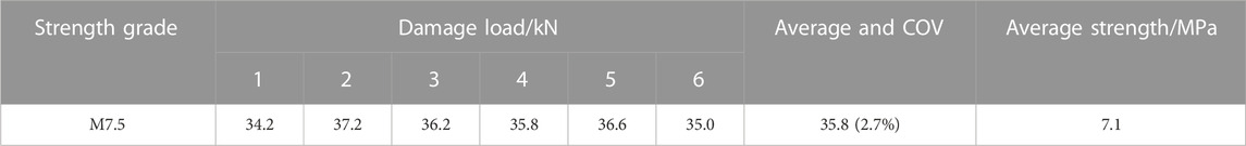
TABLE 3. Results of compressive strength of mortar specimen blocks.
The UHPC used in the experiment was independently researched and developed. The specific proportions of the raw materials are given in Table 4. Compared to conventional UHPC, this material has faster early growth in strength. It has excellent flowability which is convenient for pouring, and does not demand steam curing. The slump flow of UHPC can reach 850 mm, and the setting time of initial and final is 6 and 14 h, respectively.
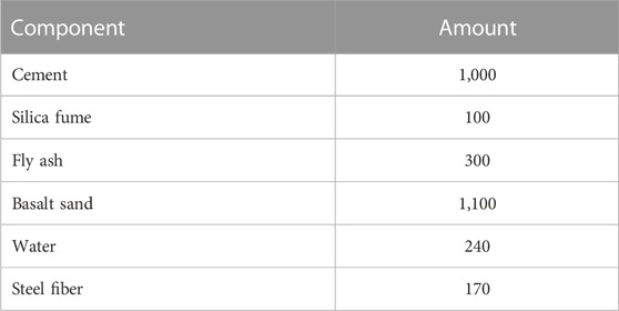
TABLE 4. Mix proportions of UHPC (unit: kg/m3).
The compressive strength of UHPC was determined through standard compression tests of 100 mm × 100 mm × 100 mm cubes with a testing procedure conforming to GB/T 31387-2015 (GB/T 31387-2015, 2015). For determining the tensile strength of UHPC, a direct tension test was performed on 3 dog-bone specimens as per T/CBMF 37-2018 (T/CBMF37-2018, 2018). According to GB/T 31387-2015 Standard (GB/T 31387-2015, 2015), the elastic modulus was obtained by three prismatic specimens with dimensions of 100 mm × 100 mm × 300 mm for UHPC. The tests set-up for the mechanical properties of UHPC are shown in Figure 2, and the test results are listed in Table 5.

FIGURE 2. Mechanical properties testing of UHPC (unit: mm).
TABLE 5. Material properties of UHPC at various ages.
In this study, the positive face of the load was used as the A face, followed by the B to the D face in a clockwise direction. In addition, the D face of specimens subjected to eccentric compression was the near eccentric face.
For axial compression columns, three vertical and one lateral strain gauges were assigned in the middle of the A and D faces. To measure the lateral displacement of the masonry column, one dial gauge was placed at 3/8H and another at 6/8H from the bottom of the B face. To measure the vertical displacement of the masonry columns, one of the dial gauges was placed in the middle of the C face. For eccentric compression columns, three vertical and one lateral strain gauges were arranged on the A face, meanwhile, three vertical strain gauges were arranged on the B and D faces. The dial gauge layout was the same as the axial compression column. Details of the layout are shown in Figure 3A.
FIGURE 3. Measuring point arrangement and test setup (unit: mm).
During the experiments, the columns were loaded by hydraulic jacks with a range of 2000 kN and the data was obtained from the pressure sensor below the jack, as shown in Figure 3B. The center line of the specimen was marked out in advance to establish the loading point, following which the loading point was aimed at the test set-up (before loading). The masonry columns were tested under displacement control at a rate of 0.1 mm/min. Before formal loading, the specimen was pre-loaded with 20 kN to determine the accuracy of the test set-up.
Brittle failure behavior was observed on unstrengthened columns in the compression test. The failure modes of unstrengthened columns are presented in Figure 4A. For the axial compression columns, no visible phenomena were observed in the early stage of loading. When the load was increased to 56%Pmax (Pmax is the peak load of masonry column), the initial crack was observed in the stones of the middle of specimen. After thet, different degrees of peeling appeared in the masonry joints, and the cracks gradually extended from the middle to the ends of the specimen. Finally, with the increase in loading, the cracks propagated through the mortar joints and local continuous cracks were formed, which resulted in the crushing of the specimen. For eccentric compression columns, the primary crack was discovered in the upper middle of the D face of the specimen (D is the near eccentric face). Then, the cracks rapidly extended in a downward direction along the masonry joints. As the load increased, the masonry joints were found to be detached on the D face. Masonry joints cracking and vertical tension cracks were observed on the B face, meanwhile, the primary crack extended towards the A and C faces. With the cracks being penetrated in the stone, the specimen lost its load-bearing capacity due to the crushing failure.
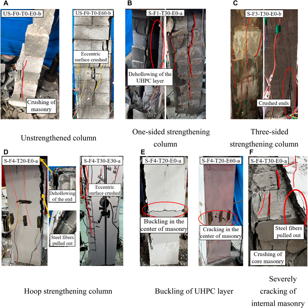
FIGURE 4. Failure modes (A) unstrengthened column; (B) one-sided strengthening column; (C) three-sided strengthening column; (D) hoop strengthening column; (E) buckling of UHPC layer; (F) severely cracking of internal masonry.
The failure of UHPC-masonry composite columns was masonry crush damage when one-sided strengthening was used. The masonry columns played a major role in the overall loading process. The UHPC layer completely detached from the masonry column substrate after the peak load. Under the axial compression, the detached UHPC layer was observed to be only slightly cracked on the surface. This was attributed that the surface of the masonry column was not fully wetted when the UHPC layer was poured. This resulted in the weak bonding performance that was exhibited between the UHPC layer and masonry columns. In this case, the compressive strength of the UHPC cannot be adequately utilized. These are illustrated in Figure 4B.
For masonry columns with three-sided strengthening, it was observed during loading that the cracks rapidly propagated from the upper to the lower end of the specimen as the load increased. When the load was increased to 42%Pmax, the sound of the steel fibers being pulled off could be heard. This indicated that the UHPC was participating in the common forces for the masonry columns during this time. With the load increased to 51%Pmax, the cracks appeared in the middle of the C face of the masonry column (C is the unstrengthened face). Subsequently, cracks were discovered in the UHPC at the bottom of the D face. In this area, the debonding was exhibited between the UHPC and masonry columns as loading increased, as given in Figure 4C. This demonstrated that the effectiveness of the UHPC layer on the end restraint of the masonry columns was not obvious with three-sided strengthening. Compared to one-sided strengthening, the UHPC was better bonded to the masonry column using three-sided strengthening. To a certain extent, this can prevent the early damage of specimens caused by poor construction techniques.
In comparison to the previous two strengthening methods, the strengthening efficiency of masonry columns was significantly enhanced through hoop strengthening. For the axial compression columns, the initial crack was discovered at the upper end of the specimen. The cracks extended towards the middle when the load was being further increased. In this case, the specimen had different degrees of damage at the ends and the UHPC appeared slightly debonded at the upper end. When loaded to peak load, a resounding sound occurred, this indicated that the strengthened columns were crushed. For the eccentric compression columns, the majority of cracks were initiated in the near eccentric face. Then, it extended to the adjacent face and formed the primary crack. With a further increase in the load, the cracks continually propagated towards the downside of the specimen. At later stage of loading, the upper end joints of the specimens were opened up. As the strengthened column was loaded to the peak load, the strengthened column was destroyed, as shown in Figure 4D.
For the strengthened columns, the final failure was caused by masonry crushing and the UHPC debonding at the mid-height of specimen. In other words, after cracks were formed in the stone and mortar, horizontal cracks appeared in the UHPC. As the load was increased, the swelling and slight buckling of the UHPC were observed in near the horizontal cracks, resulting in the UHPC layer being dehollowed, as illustrated in Figure 4E. This can be attributed to that the masonry columns did not provide lateral support to resist buckling and were allowed to swell, thus aggravating the buckling of the UHPC layer.
Additionally, the UHPC layer was chiselled away along the primary cracks of the masonry columns that were strengthened by the hoop, when the loadings were completely finished. It was noticed that the UHPC layer was tightly bonded to the masonry columns, meanwhile, the interior masonry was seriously damaged, as depicted in Figure 4F. This demonstrated that the bearing capacity of both the UHPC layer and the masonry column was maximized. Hence, the high-strength properties of UHPC can be fully exploited through hoop strengthening when masonry columns were strengthened with UHPC.
The load-displacement curves obtained from compression tests are shown in Figure 5. The force was obtained by the load cell on the steel plate. The lateral deformation was an average reading of two LVDTs (Linear Variable Displacement Transducer) on the B face and the vertical deformation was obtained from LVDT readings on the C face. It can be seen that the peak load and the stiffness of masonry columns strengthened with UHPC were improved. Overall, the loading process of the masonry columns can be divided into three stages: elastic stage, strengthening stage and descending stage.
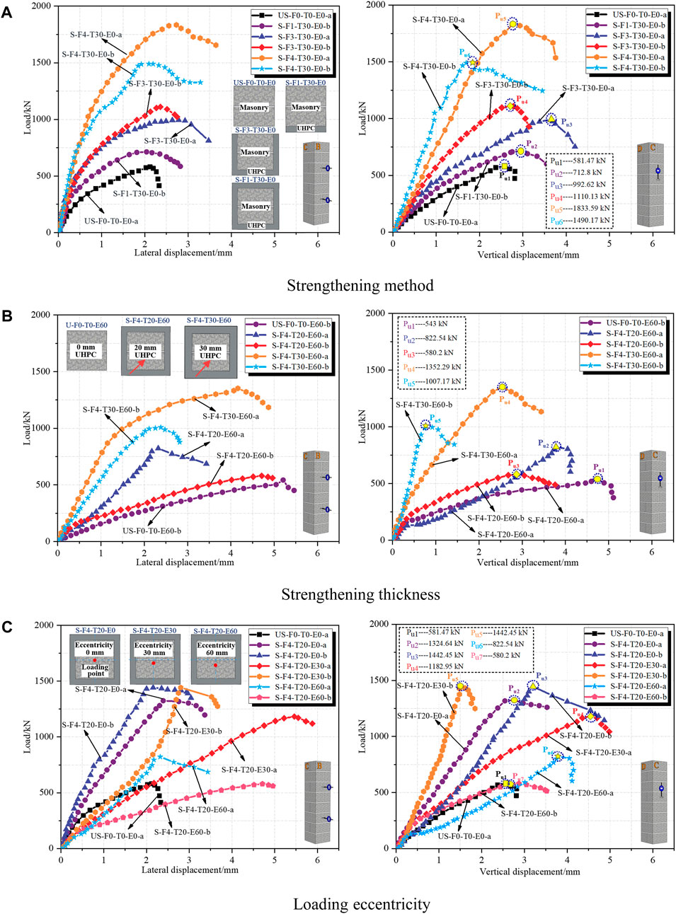
FIGURE 5. Load-displacement curves.
The elastic stage had high structural stiffness and the displacement varied relatively little with increasing load. This stage of the load-displacement curves exhibited a linear growth trend. The strengthening stage was characterized by displacements significantly greater with increasing load. Compared to the unstrengthened column, the masonry columns strengthened with UHPC exhibited a slower increase in displacement during this stage. Thus, this stage was a relatively high proportion of the whole loading process. This also clearly indicated the effectiveness of UHPC in improving the strength and ductility of masonry columns. The descending stage occurred following the peak load. In contrast to unstrengthened columns, the load on columns strengthened with UHPC did not immediately drop when the peak load was reached, instead fluctuating for a period of time. This was probably attributed to the “bridging” influence of the steel fibers in the UHPC.
The strengthening effectiveness of UHPC on masonry columns was further researched in terms of various performance parameters, such as the peak load (Pmax), displacement at peak [i.e., the displacement corresponding to the peak load, including the lateral displacement (DL) and vertical displacement (Dv)], ultimate displacement (Du), ductility (μ) and energy dissipation (E). The ductility of each group of specimens can be defined, with reference to (Wang et al., 2020), as the ratio of ultimate axial displacement (Du) to its peak axial displacement (Dv). Based on the American ACI 440.2R guideline (ACI Committee 440, 2008), the ultimate displacement was defined as the displacement corresponding to 0.85Pmax in the descending stage of axial load-displacement curves. The energy dissipation of each specimen was quantified as the area under the axial load-displacement curve to the ultimate state, i.e., the area of the shaded region in Figure 6.
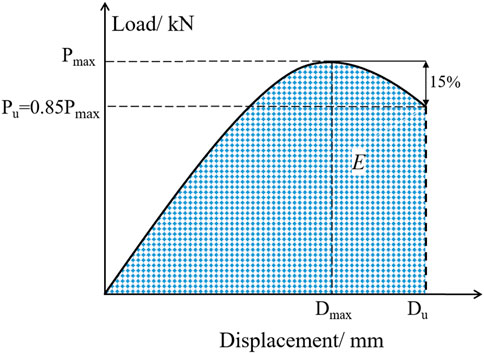
FIGURE 6. Analytical diagram of load-displacement curves.
Table 6 and Table 7 list the performance indices for the masonry columns with different parameters that were obtained from the tests. It is worth noting that the peak loads of the same groups of specimens exhibited a high degree of scatter. Based on the overall results, it was attributable to the construction quality differences and damage caused during handling.

TABLE 6. Comparison of peak load and displacement.
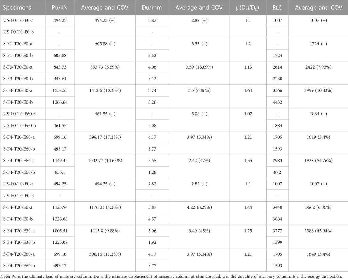
TABLE 7. Test results on characteristic parameters.
The statistical results of peak load of masonry columns are presented in the form of a histogram in Figure 7A. It is obviously noticeable that the considerable gain in peak load of the masonry columns was provided by the UHPC. Compared to unstrengthened columns, the three strengthening methods, namely, one-sided strengthening, three-sided strengthening and hoop strengthening, improved the ultimate load capacity by approximately 33.59%, 80.81%, and 185.81% respectively. Those enhancements in peak loads could be attributed to UHPC, which sustained some of the axial loads from direct contact with the masonry columns. When one-sided strengthening was utilized, the masonry columns were not adequately bonded to the UHPC, resulting in an earlier debonding of the UHPC layer from the masonry columns. Therefore, the improved bearing capacity of the masonry columns was not significant. It demonstrated that the more effective and beneficial strengthening method for masonry columns was hoop strengthening. Also, a similar rule of change could be observed between strengthening layer thickness and strengthening method. The peak load was increased by 29.17% and 117.26% with the thickness of strengthening layer from 0 to 20–30 mm. Compared to the unstrengthened columns, the peak loads were enhanced by 137.94%, 125.79% and 20.62%, respectively, with loading eccentricity from 0 to 30–60 mm. Observably, the growth rate of peak load of specimens decreased with the increase in eccentricity. The average peak load drops of groups S-F4-T20-E30 and S-F4-T20-E60 were 12.15% and 117.32%, respectively, in comparison to S-F4-T20-E0. An explanation for the fact that masonry columns failed with lower load carrying capacity under eccentric loading can be given as follows: 1) the loading eccentricity reduced the area of compression region of specimen cross-section, which directly caused the reduction of bearing capacity; 2) the lateral deformation was increased as a result of the eccentric compression. The lateral deformation would increase eccentricity of load, which further reduced the bearing capacity of specimen. It is interesting to mention that UHPC strengthening could significantly improve the peak loads of masonry columns under all eccentric loads. This improvement was especially apparent for specimens with eccentricity distances up to 30 mm (125.79%). With other eccentricity distances, the enhancement of peak loads was relatively weak.
FIGURE 7. Effect of strengthening method, strengthening thickness and eccentricity on peak load (A), lateral displacement (B), vertical displacement (C), ductility (D) and energy of destruction (E) of specimens.
The average peak displacements (including lateral and vertical displacements) of the masonry columns are shown in Figures 7B, C, respectively. It is noticeable that the deformation capacity at peak load of specimens decreased with increasing thickness of strengthening layer. This was probably caused that the UHPC layer confined the horizontal buckling deformation of masonry columns. On the other hand, the high elastic modulus of UHPC improved the bending stiffness for masonry columns. The bending stiffness was beneficial in restricting deformations. In particular, the average increases in peak lateral displacement were 7.08%, 94.81% and 66.04%, and the average increases in peak vertical displacement were 14.4%, 15.56%, and 29.57% for masonry columns strengthened with UHPC under loading eccentricities of 0mm, 30mm and 60 mm. It is worth noting that monotonic and consistent relationships were presented between deformation and loading eccentricity for control and strengthened specimens. However, the groups S-F4-T20-E30 exhibited relatively larger lateral and vertical displacements compared to the groups S-F4-T20-E60. This could be explained by the fact that, with little eccentricity, the ductility of the UHPC can provide a certain deformation capacity for masonry columns. However, masonry column substrates played a dominant role in the loading process as the eccentricity was further increased. The specimens had failed before the high ductility properties of UHPC were fully exploited, due to crushing of the masonry column substrate.
The ductility data of masonry columns with and without UHPC strengthening are shown in Figure 7D. It can be observed that the average increases in ductility were 13.08% and 44.86% when the strengthening layer thicknesses were varied from 0 to 20 and 30 mm. This can be explained in two aspects: 1) the lateral dilation of masonry core was inhibited by UHPC layer, which resulted in a significantly high axial deformation capacity. In particular, for the post-peak load, the confinement capacity could be greater owing to the rapid lateral dilation; 2) the high toughness characteristics were provided by the presence of steel fibers in the UHPC under compression. Hence, UHPC can consistently carry loads and absorb energy during the decline stage after peak loading. For masonry columns whose eccentricity was increased from 0mm to 30 mm and 60mm, the average increases in ductility were 30.91%, 13.64%, and 10%. However, the increasing trend of drop was exhibited in the average ductility. This could be influenced by the tensile effect of UHPC layers. In this case, the masonry columns were similar to concrete elements under compression subjected to a combination of axial and bending loads, presenting a weak ductility.
The energy of destruction is a crucial parameter to estimate the compressive performance of UHPC-confined masonry columns (Jing et al., 2021). The destructive energy data of each group of masonry columns are shown in Figure 7E. It can be observed that the energy absorption capacity of masonry columns strengthened with UHPC was significantly enhanced. In comparison to unstrengthened columns, when the strengthening method was changed from one-sided to three-sided and hoop, the average increases in energy of destruction were 71.2%, 140.52%, and 297.12%. The increase in energy was the lowest for group S-F2-T30-E0 (71.2%) due to the earlier dehollowing between masonry part and UHPC. The best energy dissipation was observed in group S-F4-T30-E0 (297.12%). This improvement of energy dissipation capacity was attributable to the considerable increase in masonry strength and ductility, which highlighted the superior confinement capacity of UHPC. In addition, the destruction energy of specimens increased with the increase of loading eccentricity. Compared to the control group, the average increases in destruction energy were 263.65%, 157%, and 63.75% for loading eccentricity of 0, 30, and 60 mm. Interestingly, the trend of monotonically decreasing average destruction energy was revealed, with increasing eccentricity. This indicated that the energy required to destroy masonry columns could be truly decreased by eccentricity, in spite of the additional confinement. In general, all the characteristic indices, i.e., peak load, peak displacement, ductility and energy of destruction, as well as the load-displacement curves, demonstrated that the mechanical properties of masonry columns could be significantly enhanced by UHPC.
The effect of the strengthening method, strengthening thickness and loading eccentricity on the load-strain relationship of the masonry column is depicted in Figure 8. The positive value indicated tensile strain while the negative value meant compressive strain. As shown in Figure 8, the UHPC was subject to compression in the vertical direction and tension in the lateral direction. Furthermore, the UHPC exhibited high compressive strains, of which the yield strains in the peak state were exceeded in most specimens (e.g., S-F1-T30-E0-b, S-F4-T30-E0-a, S-F4-T20-E30-b, and S-F4-T20-E60-a). This indicated that the UHPC could be well utilized in masonry column strengthening.
FIGURE 8. Load-strain curves.
It can be observed that the load-strain curves of the masonry column were approximately linear during the initial stage of the loading. The significant elastic behavior of the specimen was observed. With the increase in load, mortar joints spalling and stone internal cracking were observed under compression. The load-strain curves of the masonry column were displayed as the non-linear growth and the specimens entered the crack progression stage. With the further increase in load, the internal cracks of masonry columns continually progressed and formed local continuous cracks. This can be expressed by the load-strain curve which reached the peak and appeared to soften, i.e., the presence of a descending stage.
The load-strain relationship of the three strengthening methods is presented in Figure 8A. As expected, the strength of the masonry columns strengthened with UHPC exhibited different degrees of growth as the strengthening method was improved. For one-sided, three-sided and hoop strengthening, i.e., S-F1-T30-E0-b, S-F3-T30-E0-b. and S-F4-T30-E0-a, the strengths of the specimens were 712.8, 1110.13, and 1833.59 kN, and the ultimate tensile strains were 225.19, 1434.7, and 137.26 με, respectively in the A face, and the ultimate compressive strains were 932.27, 1694.33, and 1511.25 με, respectively in the A face, and the ultimate compressive strains were 563.02, 1309.19, and 2348.17 με, respectively in the D face. It is worth noting that the tensile strain growth of S-F4-T30-E0-a specimen (strengthened by the hoop) was relatively slow in the initial stage of loading. This can be explained that the lateral deformation of the masonry column substrate was not obvious. With the further increase in load, the lateral displacement of the masonry columns was increased, causing the tensile strain to increase rapidly. Additionally, the lower ultimate strain can be observed on the A face of the one-sided strengthened specimen, i.e., S-F1-T30-E0-b. This is mainly attributed to the earlier debonding of the UHPC-masonry interface, resulting that the strength of UHPC was not fully utilized under one-sided strengthening.
The essence of UHPC strengthened masonry columns is to work by confining the lateral deformation of the column. Hence, the lateral confining pressure exerted by UHPC on the masonry column was directly related to the strengthening effectiveness. Figure 8B shows the effect of strengthening thickness on the load-strain relationship. It can be seen that the ultimate strain of the masonry column was improved as the strengthening thickness increased. This is due to the increase in strengthening thickness, which enhanced the confinement effect of UHPC on the masonry columns. Correspondingly, the ultimate load capacity and strain of the masonry columns were raised. The results of these tests indicated that the confining effect created by the UHPC layer provided additional horizontal support to the masonry columns. In addition, it should be noted that the strain of specimens under the same load decreased with increasing strengthening thickness. Comparing specimens S-F4-T30-E60-a and S-F4-T20-E60-b, the compressive strains on the A face were 298.34 and 698.89 με respectively when the load was 300 kN. This is because, with increasing strengthening thickness, the stiffness of the masonry columns was enhanced. The confinement effect of the UHPC on masonry column increased, and the lateral deformation of masonry column strengthened with UHPC was decreased, resulting in the reduction of strains.
The effect of eccentricity on the load-strain relationship of masonry columns is shown in Figure 8C. It can be observed that the initial stiffness of the masonry columns showed great differences even in the same group of specimens. This may be caused by the complicated deformation of columns strengthened with UHPC. During the whole loading process, the ultimate strain of masonry columns decreased with the increase in eccentricity. This can be explained that the increase in eccentricity decreased the load-carrying capacity of the masonry column. Consequently, the ultimate strain of the masonry column was reduced. Besides, it can be seen that the strain growth rate of the specimen near the eccentric face (i.e., D face) was faster than that far from the eccentric face (i.e., B face). Taking specimen S-F4-T20-E30-b as an example, the strain on the B face was 221.75 με and the strain on the D face was 1,242.96 με under the same load of 500 kN. This is attributed that eccentric loading causing a strain gradient in the axial deformation of the masonry column. It exhibited a non-uniform distribution in strain and the strain growth was faster on the near eccentric face.
Presently, there are two main categories for masonry modeling, separated and monolithic (Pérez and Ortiz-Lozano, 2020). For the monolithic model, mortar and block, which are originally discrete medium aggregates, are treated as a unity of homogeneous and continuous materials. Then, the blocks and mortar are assigned the integral material properties of the masonry in ABAQUS. In this modeling approach, the bond slip and corresponding elastic compression of the block and mortar are ignored. This resulted that the mechanical mechanisms of the masonry cannot be adequately displayed after cracking. Cerrolaza et al. (1999) had shown that the monolithic model was more effective for the macro component size five times larger than the block. Separate modeling, in which the block and mortar are distinguished and given separate material properties. The difference in the constitutive relationship between block and mortar can be reflected by this model. In this paper, the separated modeling was used to model the masonry specimens. The stone and mortar units were modeled separately and were assigned separate material properties. Additionally, the analysis of the strengthening effect of UHPC on masonry columns was concentrated in the present paper, while the mechanical properties between stone and mortar were not investigated. Therefore, the contact properties of the stone and mortar can be referred to in literature (Guo, 2020), using the “Tie” function as simple bonding.
The extensive unit library is available in ABAQUS. In this numerical simulation, the eight-noded hexahedral linear reduction integration element (C3D8R) was utilized to simulate the UHPC, stone, mortar, and loaded end. The C3D8 element has the advantages of accurate displacement solution, excellent stability of element twist, suitable for contact analysis and no “shear self-locking” (Shi, 2006). In this study, the finite element (FE) model was a symmetrical structure and half of the structure was modeled to save computational resources. Taking specimen S-F4-T20-E60 as an example, the FE model and meshing of the UHPC-masonry column specimen are shown in Figure 9.
FIGURE 9. The FE model and meshing of UHPC-masonry column.
Hussein et al. (2017); Jang et al. (2018) applied a traction-separation model to simulate the behavior of the UHPC-HPC interface and the UHPC joint push-out tests, respectively. This approach was similarly applied in this paper to simulate the bonding behavior of the UHPC-masonry interface. The traction-separation model, which establishes the constitutive relationship between the interfacial stress and the separation. It consists of the linear elastic traction-separation, the damage initial criterion (DIC) and the damage evolution. The traction-separation response described in the ABAQUS analysis manual is given in Figure 10.
FIGURE 10. Typical traction-separation response with exponential damage evolution.
Where
There are four primary damage criteria in ABAQUS, namely, Maxs Damage, Maxe Damage, Quads Damage and Quade Damage. However, the failure strain is extremely difficult to measure, and Maxs Damage would lead to a conservative result. Therefore, Quads Damage was used in this paper, as shown in Eq. 1.
Where
The concrete damage plasticity (CDP) model is based on the uniaxial compressive and tensile stress-strain relationship of concrete materials. Its theory of tensile and compressive damage was used to characterize the inelastic behavior of concrete. In this paper, the CDP model was utilized to simulate the UHPC material. The UHPC constitutive model used for the numerical simulations was obtained from the literature (Yang, 2007; Zhang et al., 2015) and is shown in Figure 11. The calculated procedures for UHPC compressive and tensile stress-strain relationship are given in Eq. 2, 3. Where,
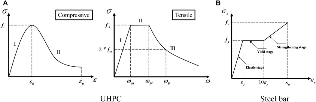
FIGURE 11. Constitutive law of UHPC and steel bar 4.1.4.3 Stone and mortar.
In order to accomplish the definition of the CDP model. Five main parameters [i.e., the dilation angle (
TABLE 8. Values of CDP model parameters of UHPC, stone and mortar.
The damage factor
where the subscripts k = c and t indicate axial compression and tension, respectively.
The trilinear constitutive model proposed by the code (GB 50010-2010, 2010) was used for the reinforcement, as shown in Figure 11.
Where
According to the relevant literature, the compressed constitution of stone and mortar in this study are shown in Eq. 5, 6, respectively.
Where
Considering the plastic damage of stone and mortar, the formula for calculating the damage factor (Eq. 7) and the values of CDP model parameters (Table 8) were given.
In this section, the damage evolution and failure modes of FE model of masonry columns were summarized. The extent of damage to the model is quantified depending on the compression damage variable (DAMAGEC), where 0 indicates no damage and 1 indicates that the model is total loss of strength (El Ezz and Galal, 2017). Meanwhile, the peak loads of the FE model were compared with the test results, as showed in Figure 12. In particular, the errors were between 0.7% and 7.6%, indicating a good agreement on the simulation and test results. The validity of the ABAQUS simulation results was confirmed. It is notable that the bearing capacities predicted by the numerical simulations were slightly higher than the results of the experimental investigation. This can be attributed to shortcomings during fabrication and testing of the specimen in the experiment.
FIGURE 12. The comparison of peak loads from teats and FE models.
The damage progression and failure modes predicted by the numerical model were compared with experimental results. Comparison of failure modes for masonry columns under strengthening methods is illustrated in Figure 13A, i.e., the specimens of US-F0-T0-E0, S-F1-T30-E0, S-F3-T30-E0, and S-F4-T30-E0. As the peak load was reached, it can be seen that all the mortar joints were slightly damaged and the upper stones were seriously damaged. With improved methods of strengthening, the damage factor of the UHPC was increased, meanwhile the damage to the masonry columns was effectively relieved. This confirmed the usability of UHPC in masonry strengthening applications. Comparing the compressive damage progression under the failure load, the failure mode was observed to be consistent with the test. For the one-sided strengthening model, the failure was caused by the masonry columns being completely crushed and no extensive damage was observed by the UHPC. The similar phenomenon was observed during the experiments due to the earlier debonding of the UHPC from the masonry columns. In contrast, the effectiveness of the masonry column strengthening with three-sided and hoop strengthening was significantly enhanced. This is attributed to the bond between the UHPC and masonry columns was significantly improved, which resulted in the UHPC being adequately utilized and the synergy between the UHPC and the masonry columns was achieved. The satisfactory agreement was found in the test and FE model, except for the S-F1-T30-E0 group. The main reason is that the specimens were damaged during the tests due to fabrication and handling, which resulted in the lower load capacity of the masonry columns. However, the error of ultimate load carrying capacity between the tested and simulated was 7.6%, which was within the acceptable range. It was observed that the ultimate load capacity of the masonry columns was most significantly increased by the hoop strengthening. Compared to S-F3-T30-E0, the UHPC was subject to heavier damage in S-F4-T30-E0. This means that the masonry columns were protected by the UHPC, which caused in less damage to the masonry columns.
FIGURE 13. Comparison of finite element analysis and experimental results under strengthening methods and eccentric distances.
Figure 13A, i.e., the specimens of S-F4-T20-E0, S-F4-T20-E30, and S-F4-T20-E60, shows the progression of compression damage of FE models under different eccentric distances. It can be seen that the trend was approximately the same for the compressive damage in the models as the crack propagation in the tests. The masonry interior of the axial model was crushed at the peak load, where the UHPC damage was also substantial. At an eccentricity of 30 and 60 mm, the models exhibited the similar form of damage. The damage initially appeared on the near eccentric face of the masonry column, and progressed along the adjacent face. Meanwhile, the damage of the UHPC layer was extended from this area towards the adjacent face. The damage of masonry columns and UHPC was drastically reduced with increasing eccentricity when the failure load was reached. Simultaneously, the compression damage to the dorsal eccentric face showed a decreasing trend. When the eccentricity was increased to 60 mm, the compression damage factor of the dorsal eccentric face became 0, and it probably presented tensile damage state.
The experimental load-displacement curves and FEM numerical curves of masonry columns under different strengthening methods and loading eccentricities are presented in Figure 13B. The predicted curves obtained by FEM specimens were in excellent agreement in terms of initial stiffness and peak load in comparison with the test results. However, the overestimates of FEM were observed in the post-peak behavior. This could be attributed to the fact that, in the FEM, a perfect bond between stone units and mortar was assumed. In conclusion, the overall trends of load-displacement curves obtained from FEM were satisfactory with test results. In comparison with test results, the peak load discrepancy of specimens was within 7.6%, and the overall behavior was adequately captured by the FEM.
Figure 14 presents the progression of compression damage to the model under different strengthening thicknesses. As can be seen from Figure 14A, the damages of the masonry columns decreased as the strengthening thickness increased, in the meantime the damage of UHPC increased. This means that the UHPC was involved in the masonry column synergy, and shared partial loads of the masonry column. This phenomenon was particularly noticeable in the compressive damage progression of the failure load. With increasing strengthening thickness, the damage to the masonry columns did not differ significantly, while the damage to the UHPC was considerably increased. This confirmed the effectiveness of UHPC in strengthening masonry columns.
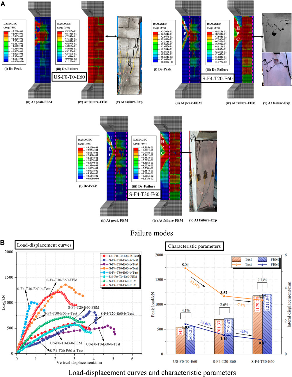
FIGURE 14. Comparison of finite element analysis and experimental results under strengthening thicknesses.
The experimental load-displacement curves and FEM numerical curves of masonry columns under strengthening thickness are presented in Figure 14B. For specimens with thickness of strengthening layer increased, the strength in failure was overestimated by the models owing to the changes in stiffness and confinement stresses of UHPC. The results of numerical modelling and experimental results showed that numerical models were in close agreement with the experimental results with regard to the overall response of masonry columns strengthened with UHPC. In addition, the peak loads and corresponding lateral displacements for the FE models were extracted, which were compared with the test, as shown in Figure 14B. It is observed that the lateral displacement was reduced at the peak load due to the UHPC layer being sufficient to restrict the horizontal buckling of the masonry columns. In addition, it is worth noting that the FE models were in good agreement with the peak loads of the test results, but the lateral displacements were considerably different. However, the overall trend in lateral displacement was consistent, both presenting a decrease with the strengthening thickness. The main reason for this was that the lateral displacements could not be accurately modelled by ABAQUS after the masonry columns had cracked. The cracking of masonry columns was only represented by the damage factor reaching a discount to the stiffness. In contrast, the software was relatively accurate for the simulation of the ultimate bearing capacity of masonry columns.
In practical strengthening engineering, the thickness of the strengthening plays an important role in the bearing capacity and durability of the structure. In order to investigate the optimum strengthening thickness for enhancing the ultimate bearing capacity of the masonry columns under axial compression. On the basis of the hoop strengthening, the FE models of 6 groups were designed. These models had a strengthening thickness of 35, 40, 45, 50, 55 and 60 mm, respectively. Figure 15 shows the relationships between strengthening thickness and the peak load raising rate of the FE models together with the corresponding lateral displacement.
FIGURE 15. Effect of strengthening thickness on peak load raising rate and lateral displacement of masonry columns.
Figure 16 presents the compressive damage progression of the FEM under different strengthening thicknesses. No significant distinctions in UHPC damage were observed when the strengthening thickness was less than 50mm, and the majority of damage concentrated in the upper part of the column, as shown in Figure 16A. Eventually, the masonry columns were excessively damaged leading to the overall failure of the structure. At this thickness, the damage of UHPC and masonry column in the lower region was poor, and neither the UHPC nor the masonry column were fully utilized, as can be seen from Figure 16B. It was observed that the damage of UHPC extended towards the lower end of the masonry column when the strengthening thickness reached 50 mm or more. It indicates that the utilization of UHPC had been enhanced, resulting in the whole bearing capacity of the masonry columns was increased.
FIGURE 16. Compression damage progression of models with different strengthening thicknesses.
Obviously, as the thickness of the strengthening was increased, the bearing capacity of the masonry columns and the utilization of UHPC were improved. However, in practical engineering, the thickness cannot be increased indefinitely. On the one hand, the phenomenon is easily seen that the original structure had been damaged while the strengthening layer had not yet reached its own ultimate state. This can result in material properties not being adequately utilized, and economic waste. On the other hand, the weak areas for the overall structure (except for the strengthening layer) are easily formed and result in serious damage, which is a safety risk. Hence, considering economic and safety factors, it was recommended that the thickness of the strengthening should be 50 mm.
Besides, the strengthening layer was extremely susceptible to debonding from the masonry columns, which was observed in the tests. Resulting in that UHPC cannot adequately participate in the synergistic forces of the masonry columns. This was reflected in the FE model by a slight or no damage factor of the strengthening layer. Therefore, based on the optimal strengthening thickness model, the strengthening efficiency of UHPC was analyzed by keyway and planting bars at the bond interface. Figure 17 shows the progression of compression damage for the two types of interface treatment.

FIGURE 17. Compression damage progression of the models.
The peak loads of the keyway and planting bars calculated using the FE model were 3050 kN and 3377.02kN, respectively. As can be seen in Figures 17B, C, the UHPC damage factor was significantly increased for the model after the interface treatment compared to S-F4-T50-E0 (i.e., Figure 17A). In addition, the masonry columns were more adequately damaged. This was probably caused that the bonding of the UHPC to the masonry column was enhanced by the interface treatment, which increased the effective area to be subjected to the load. Consequently, the whole of the model was subjected to a more homogeneous force, while the bearing capacity of the masonry columns was dramatically increased. Overall, the combination of a keyway or a planting bars with UHPC was recommended when the UHPC was applied to strengthening engineering. Its aims to maximize the superior performance of UHPC, and thus improved the load bearing capacity and durability of the structure.
The primary conclusions were the following:
(1) Compared to unstrengthened column, the compressive behavior of masonry columns strengthened with UHPC was considerably improved. The masonry column failure mode was changed by UHPC confinement. Numerous small cracks were observed in the strengthened masonry columns only on the UHPC surfaces, instead of a few large vertical cracks in the unstrengthened columns. Ductile failure behavior was exhibited in masonry columns strengthened using UHPC, owing to the crack bridging capacity of the steel fibers in the interface. Moreover, the high elastic modulus of UHPC provided a guarantee for the initial compressive stiffness of the masonry columns.
(2) In terms of strengthening methods, the hoop strengthening provided a greater gain in maximum load and deformation capacity of masonry columns as compared to one-sided and three-sided strengthening. The increase in peak load, ductility and dissipated energy of masonry columns under hoop strengthening were 185.81%, 49.09% and 185.81%, respectively, against unstrengthened columns. Meanwhile, crushing failure of masonry columns can be retarded by hoop reinforcement, and good integrity of masonry columns strengthened using hoop was observed at failure. In practical engineering, we recommend that hoop strengthening should be privileged over other strengthening methods in the selection of UHPC strengthening techniques.
(3) For masonry columns strengthened with UHPC, the compressive strength, ductility and energy consumption capacity can be significantly increased by increasing thickness of strengthening layer. As the thickness of strengthening layer was increased from 0mm to 20 mm and 30mm, the increase range of strength was from 29.17% to 117.26%, the increase range of ductility was from 13.08% to 44.86%, and the increase range of energy dissipation capacity was from −12.47% to 2.34%. In addition, the lateral displacement corresponding to the peak load was decreased by 32.44% and 37.24%. It was demonstrated that the strength of masonry columns was raised by UHPC, and crushing damage of the structure could be mitigated.
(4) Whether UHPC was used or not, the bearing capacity of masonry columns was decreased with the increase of eccentricity. However, compared with the unstrengthened masonry columns (US-F0-T0-E60), the peak load of the S-F4-T20-E60 column strengthened with UHPC increased by 29.17%. This phenomenon demonstrated the effectiveness of UHPC in strengthening masonry columns under eccentric loading.
(5) The FE model of UHPC strengthened masonry columns was established by ABAQUS. The simulation results were verified against the experimental results and the error value was within 7.6%. The model was successful in simulating the strength and failure mode of masonry columns.
In general, the capacity, ductility and stiffness of masonry columns can be enhanced significantly by using UHPC strengthening. However, a weak interface existed in the UHPC-masonry columns, which was vulnerable to damage caused by interfacial peeling. Therefore, the shear capacity of these interfaces should be concerned in the design in order to avoid structural damage owing to interfacial peeling.
The original contributions presented in the study are included in the article/Supplementary Material, further inquiries can be directed to the corresponding author.
ZJ: Writing–original draft, Investigation. JY: Conceptualization, Data curation, Writing–review and editing. HS: Software, Writing–review and editing.
The author(s) declare financial support was received for the research, authorship, and/or publication of this article. The authors highly appreciate the financial support from the National Natural Science Foundation of China (Grant Nos 52278293, U20A20314), and Project of Science and Technology Program of Department of Transport, Hubei Province (2020-186-1-6), the Science and Technology Research Program of Chongqing Municipal Education Commission (KJZD-M202300706), Chongqing Science and Technology Project (CSTB2022TIAD-KPX0205), and Guangxi key research and development plan project (Grant No. GuikeAB22036007).
Author JY was employed by the company Guangxi Communications Investment Group Co., Ltd.
The remaining authors declare that the research was conducted in the absence of any commercial or financial relationships that could be construed as a potential conflict of interest.
All claims expressed in this article are solely those of the authors and do not necessarily represent those of their affiliated organizations, or those of the publisher, the editors and the reviewers. Any product that may be evaluated in this article, or claim that may be made by its manufacturer, is not guaranteed or endorsed by the publisher.
ABAQUS (2012). ABAQUS, standard user’s manual, version 6.12 Providence. RI (USA): Dassault Systemes Corp.
ACI Committee 440 (2008). Guide for the design and construction of externally bonded FRP systems for strengthening concrete structures ACI 440.2R-08. Farmington Hills: MI.
Alotaibi, K. S., and Galal, K. (2018). Experimental study of CFRP-confined reinforced concrete masonry columns tested under concentric and eccentric loading. Compos. Part B Eng. 155, 257–271. doi:10.1016/j.compositesb.2018.08.024
Angiolilli, M., Gregori, A., Pathirage, M., and Cusatis, G. (2020). Fiber Reinforced Cementitious Matrix (FRCM) for strengthening historical stone masonry structures: experiments and computations. Eng. Struct. 224, 111102. doi:10.1016/j.engstruct.2020.111102
Babaeidarabad, S., Arboleda, D., Loreto, G., and Nanni, A. (2014). Shear strengthening of un-reinforced concrete masonry walls with fabric-reinforced-cementitious-matrix. Constr. Build. Mater. 65, 243–253. doi:10.1016/j.conbuildmat.2014.04.116
Bahmani, H., and Mostofinejad, D. (2022). Microstructure of ultra-high-performance concrete (UHPC)–A review study. J. Build. Eng. 50, 104118. doi:10.1016/j.jobe.2022.104118
Bajaber, M. A., and Hakeem, I. Y. (2021). UHPC evolution, development, and utilization in construction: a review. J. Mater. Res. Technol. 10, 1058–1074. doi:10.1016/j.jmrt.2020.12.051
Cerrolaza, M., Sulem, J., and Elbied, A. (1999). A Cosserat non-linear finite element analysis software for blocky structures. Adv. Eng. Softw. 30 (1), 69–83. doi:10.1016/s0965-9978(98)00059-3
Dadvar, S. A., Mostofinejad, D., and Bahmani, H. (2020). Strengthening of RC columns by ultra-high performance fiber reinforced concrete (UHPFRC) jacketing. Constr. Build. Mater. 235, 117485. doi:10.1016/j.conbuildmat.2019.117485
Deng, M., and Li, T. (2020). Masonry columns strengthened with bar mesh highly ductile fiber reinforced concrete (BMHDC) jacket under concentric and eccentric loads. Constr. Build. Mater. 237, 117606. doi:10.1016/j.conbuildmat.2019.117606
El Ezz, A. A., and Galal, K. (2017). Compression behavior of confined concrete masonry boundary elements. Eng. Struct. 132, 562–575. doi:10.1016/j.engstruct.2016.11.043
El-Sokkary, H., and Galal, K. (2019). Performance of eccentrically loaded reinforced-concrete masonry columns strengthened using FRP wraps. J. Compos. Constr. 23 (5), 04019032. doi:10.1061/(asce)cc.1943-5614.0000958
Farzad, M., Sadeghnejad, A., Rastkar, S., Moshkforoush, A., and Azizinamini, A. (2020). A theoretical analysis of mechanical and durability enhancement of circular reinforced concrete columns repaired with UHPC. Eng. Struct. 209, 109928. doi:10.1016/j.engstruct.2019.109928
Fossetti, M., and Minafò, G. (2017). Comparative experimental analysis on the compressive behaviour of masonry columns strengthened by FRP, BFRCM or steel wires. Compos. Part B Eng. 112, 112–124. doi:10.1016/j.compositesb.2016.12.048
Fossetti, M., and Minafò, G. (2016). Strengthening of masonry columns with BFRCM or with steel wires: an experimental study. Fibers 4 (4), 15. doi:10.3390/fib4020015
Guo, H. B. (2020). Numerical simulation study on bond behavior of FRP-masonry interface under single shear action. Yunnan, China: Yunnan University.
H. Marthys, and L. Noland (Editors) (1989). Proceedings of an international seminar on evaluation, strengthening, and retrofitting masonry buildings (Colorado: TMS).
Hung, C. C., and Yen, C. H. (2021). Compressive behavior and strength model of reinforced UHPC short columns. J. Build. Eng. 35, 102103. doi:10.1016/j.jobe.2020.102103
Hussein, H. H., Walsh, K. K., Sargand, S. M., Ai Rikabi, F. T., and Steinberg, E. P. (2017). Modeling the shear connection in adjacent box-beam bridges with ultrahigh-Performance concrete joints. I: model calibration and validation. J. Bridge Eng. 22 (8), 4017043. doi:10.1061/(asce)be.1943-5592.0001070
Jang, H. O., Lee, H. S., Cho, K., and Kim, J. (2018). Numerical and experimental analysis of the shear behavior of ultrahigh-performance concrete construction joints, Adv. Mater. Sci. Eng. 2018 1–17. doi:10.1155/2018/6429767
Jing, L., Yin, S., and Aslani, F. (2021). Experimental investigation on compressive performance of masonry columns confined with textile-reinforced concrete. Constr. Build. Mater. 269, 121270. doi:10.1016/j.conbuildmat.2020.121270
Khan, M. I., Al-Osta, M. A., Ahmad, S., and Rahman, M. K. (2018). Seismic behavior of beam-column joints strengthened with ultra-high performance fiber reinforced concrete. Compos. Struct. 200, 103–119. doi:10.1016/j.compstruct.2018.05.080
Kouris, L. A. S., and Triantafillou, T. C. (2018). State-of-the-art on strengthening of masonry structures with textile reinforced mortar (TRM). Constr. Build. Mater. 188, 1221–1233. doi:10.1016/j.conbuildmat.2018.08.039
Krevaikas, T. D., and Triantafillou, T. C. (2005). Masonry confinement with fiber-reinforced polymers. J. Compos. Constr. 9 (2), 128–135. doi:10.1061/(asce)1090-0268(2005)9:2(128)
Li, H. Y. (2009). Parametric identification for reactive powder concrete damage plasticity constitutive model and FEM verification. Beijing, China: Beijing Jiaotong University.
Li, T., Deng, M., Jin, M., Dong, Z., and Zhang, Y. (2021a). Performance of axially loaded masonry columns confined using textile reinforced concrete (TRC) added with short fibers. Constr. Build. Mater. 279, 122413. doi:10.1016/j.conbuildmat.2021.122413
Li, T., Deng, M., Jin, M., and Zhang, Y. (2022). Experimental study on axial compressive behavior of full-scale masonry columns strengthened with reinforced high ductile concrete (RHDC). Eng. Struct. 252, 113650. doi:10.1016/j.engstruct.2021.113650
Li, T., Deng, M., and Zhang, Y. (2021b). Effect of eccentricity on strengthening efficiency of bar mesh high ductile concrete (BMHDC) on slender masonry columns. Eng. Struct. 230, 111732. doi:10.1016/j.engstruct.2020.111732
Liu, K. (2021). Study on interfacial bonding mechanical properties of NSC-UHPC wet joint. Beijing, China: Beijing University of Civil Engineering and Architecture.
Murgo, F. S., and Mazzotti, C. (2019). Masonry columns strengthened with FRCM system: numerical and experimental evaluation. Constr. Build. Mater. 202, 208–222. doi:10.1016/j.conbuildmat.2018.12.211
Pérez, Y. C., and Ortiz-Lozano, J. A. (2020). Fragility curves based on the numerical analysis of masonry walls against subsidence, using the Abaqus/CAE software and relying on the pulldown technique. Rev. Int. métodos Numér. Cálc. diseño Ing. 36 (1). doi:10.23967/j.rimni.2019.11.002
Prem, P. R., and Murthy, A. R. (2016). Acoustic emission and flexural behaviour of RC beams strengthened with UHPC overlay. Constr. Build. Mater. 123, 481–492. doi:10.1016/j.conbuildmat.2016.07.033
Qiao, W. J. (2014). Study on model test and engineering application of masonry arch-bridge reinforced with composite arch circle. Xi’an, China: Chang’an University.
Ragalwar, K., Heard, W. F., Williams, B. A., Kumar, D., and Ranade, R. (2020). On enhancing the mechanical behavior of ultra-high performance concrete through multi-scale fiber reinforcement. Cem. Concr. Compos. 105, 103422. doi:10.1016/j.cemconcomp.2019.103422
Shao, Y., Kuo, C. W., and Hung, C. C. (2021). Seismic performance of full-scale UHPC-jacket-strengthened RC columns under high axial loads. Eng. Struct. 243, 112657. doi:10.1016/j.engstruct.2021.112657
Shi, C., Wu, Z., Xiao, J., Wang, D., Huang, Z., and Fang, Z. (2015). A review on ultra high performance concrete: part I. Raw materials and mixture design. Constr. Build. Mater. 101, 741–751. doi:10.1016/j.conbuildmat.2015.10.088
Shi, Y. P. (2006). Detailed examples of ABAQUS finite element analysis. China: Machinery Industry Press.
T/CBMF37-2018 (2018). Fundamental characteristics and test methods of ultra-high performance concrete. Beijing: CN.
Vincent, T., and Ozbakkaloglu, T. (2013). Influence of fiber orientation and specimen end condition on axial compressive behavior of FRP-confined concrete. Constr. Build. Mater. 47, 814–826. doi:10.1016/j.conbuildmat.2013.05.085
Wang, J., Wan, C., Zeng, Q., Shen, L., Malik, M. A., and Yan, D. (2020). Effect of eccentricity on retrofitting efficiency of basalt textile reinforced concrete on partially damaged masonry columns. Compos. Struct. 232, 111585. doi:10.1016/j.compstruct.2019.111585
Wang, Z., Yang, J., Zhou, J., Yan, K., Zhang, Z., and Zou, Y. (2022). Strengthening of existing stone arch bridges using UHPC: theoretical analysis and case study. Struct 43, 805–821. doi:10.1016/j.istruc.2022.06.055
Witzany, J., Čejka, T., and Zigler, R. (2014). Failure mechanism of compressed short brick masonry columns confined with FRP strips. Constr. Build. Mater. 63, 180–188. doi:10.1016/j.conbuildmat.2014.04.041
Yang, J. (2007). Flexural behavior of ultra-high performance concrete beams prestressed with CFRP tendons. Changsha, China: Hunan University.
Yang, J., Chen, R., Zhang, Z., Zou, Y., Zhou, J., and Xia, J. (2023). Experimental study on the ultimate bearing capacity of damaged RC arches strengthened with ultra-high performance concrete. Eng. Struct. 279, 115611.
Yoo, D. Y., and Banthia, N. (2016). Mechanical properties of ultra-high-performance fiber-reinforced concrete: a review. Cem. Concr. Compos. 73, 267–280. doi:10.1016/j.cemconcomp.2016.08.001
Youssf, O., Hassanli, R., and Mills, J. E. (2017). Retrofitting square columns using FRP-confined crumb rubber concrete to improve confinement efficiency. Constr. Build. Mater. 153, 146–156. doi:10.1016/j.conbuildmat.2017.07.108
Yuan, W., Wang, X., Guo, A., Li, C., Dong, Z., and Wu, X. (2022). Cyclic performance of RC bridge piers retrofitted with UHPC jackets: experimental investigation. Eng. Struct. 259, 114139. doi:10.1016/j.engstruct.2022.114139
Zhang, J. (2014). Experimental research on mechanical performance of stone arch bridge strengthened by the enclosed reinforced concrete. Chengdu, China: Southwest Jiaotong University.
Zhang, Y., Li, X., Zhu, Y., and Shan, X. (2020). Experimental study on flexural behavior of damaged reinforced concrete (RC) beam strengthened by toughness-improved ultra-high performance concrete (UHPC) layer. Compos. Part B Eng. 186, 107834. doi:10.1016/j.compositesb.2020.107834
Zhang, Y., Yang, J., Li, T., and Deng, M. (2022). Mechanical behavior of RC columns strengthened with thin UHPC jacket under cyclic loads. J. Build. Eng. 49, 104065. doi:10.1016/j.jobe.2022.104065
Zhang, Y., Zhu, Y., Yeseta, M., Meng, D., Shao, X., Dang, Q., et al. (2019). Flexural behaviors and capacity prediction on damaged reinforcement concrete (RC) bridge deck strengthened by ultra-high performance concrete (UHPC) layer. Constr. Build. Mater. 215, 347–359. doi:10.1016/j.conbuildmat.2019.04.229
Zhang, Z., Shao, X. D., Li, W. G., Zhu, P., Chen, H., Zhang, D. W., et al. (2015). Prediction of the next highly pathogenic avian influenza pandemic that can cause illness in humans. China J. Highw. Transp. 28 (8), 50. doi:10.1186/s40249-015-0083-8
Zhang, Z., Pang, Z., Xu, L., Zou, Y., Yang, J., and Wang, C. (2023). The bond properties between UHPC and stone under different interface treatment methods. Constr. Build. Mater. 365, 130092.
Zhu, Y., Zhang, Y., Hussein, H. H., and Chen, G. (2020). Flexural strengthening of reinforced concrete beams or slabs using ultra-high performance concrete (UHPC): a state of the art review. Eng. Struct. 205, 110035. doi:10.1016/j.engstruct.2019.110035
Zou, Y., Yu, K., Heng, J., Zhang, Z., Peng, H., and Wu, C. (2023a). Feasibility study of new GFRP grid web - Concrete composite beam. Compos. Struct. 305, 116527.
Zou, Y., Zheng, K., Zhou, Z., Zhang, Z., Guo, J., and Jiang, J. (2023b). Experimental study on flexural behavior of hollow steel-UHPC composite bridge deck. Eng. Struct. 274, 115087.
Keywords: ultra-high performance concrete (UHPC), performance improvement, masonry structure, compressive performance, building structure
Citation: Jiang Z, Yang J and Su H (2023) Mechanical response of masonry structure strengthened with ultra-high performance concrete (UHPC): a comparative analysis for different strengthening tactics. Front. Mater. 10:1289225. doi: 10.3389/fmats.2023.1289225
Received: 05 September 2023; Accepted: 06 October 2023;
Published: 20 October 2023.
Edited by:
Anbang Li, Xi’an University of Architecture and Technology, ChinaCopyright © 2023 Jiang, Yang and Su. This is an open-access article distributed under the terms of the Creative Commons Attribution License (CC BY). The use, distribution or reproduction in other forums is permitted, provided the original author(s) and the copyright owner(s) are credited and that the original publication in this journal is cited, in accordance with accepted academic practice. No use, distribution or reproduction is permitted which does not comply with these terms.
*Correspondence: Jun Yang, eWFuZ2p1bkBjcWp0dS5lZHUuY24=
Disclaimer: All claims expressed in this article are solely those of the authors and do not necessarily represent those of their affiliated organizations, or those of the publisher, the editors and the reviewers. Any product that may be evaluated in this article or claim that may be made by its manufacturer is not guaranteed or endorsed by the publisher.
Research integrity at Frontiers
Learn more about the work of our research integrity team to safeguard the quality of each article we publish.