 Shitao Wang1
 Haibing Zhang2*
- 1Unit 31002, People’s Liberation Army of China, Beijing, China
- 2Naval Aviation University Qingdao Branch, Qingdao, China
Stiffened plates are widely used in engineering due to their excellent manufacturing and mechanical properties. This paper introduces a novel method for designing stiffener plates that combines the H-DGTP formulation, robust topology optimization formulation, and maximum length-scale control. In comparison to existing methods, the proposed approach not only provides a clear layout of stiffeners but also optimizes their height. Sensitivity analysis of all design variables is derived for utilization with gradient-based optimizers. The study demonstrates that the implementation of the robust filter approach enables precise control of both structural features and gap widths, effectively avoiding sharp angles. Moreover, as the maximum length approaches the minimum length, the stiffeners assume uniform thickness, which better meets engineering requirements. Numerical examples are presented to validate the effectiveness of the proposed method.
1 Introduction
For a given load, the addition of ribs or stiffeners to a plate or shell structure can significantly enhance its stiffness and vibrational characteristics. As a result, stiffened plates or shells find extensive application as primary or secondary load-bearing components in various fields including automotive, aerospace, and civil engineering structures. They offer notable advantages in terms of ease of manufacturing and a high rigidity-to-weight ratio. However, it should be noted that the layout, size, and shape of the stiffeners have a profound impact on the mechanical properties of such structures. Consequently, the establishment of a systematic design method holds great importance for engineers and researchers seeking to optimize the performance of stiffened plates or shells.
Topology optimization is a widely used method for optimizing initial designs by adjusting their geometric and material properties, considering a set of specified objectives and constraints. Over the past few decades, several topology optimization methods have been developed to determine the optimal layout of the structures. These methods include homogenization-based methods (Bendsøe and Kikuchi, 1988), density-based methods (Bendsøe and Bendsoe, 1989; Zhou and Rozvany, 1991), level set methods (Wang et al., 2003; Allaire et al., 2004), evolution methods (Xie and Steven, 1993), and feature-mapping methods (Guo et al., 2014; Zhang et al., 2017). Also, they have been successfully applied to numerous engineering structures (Liu et al., 2015a; Li et al., 2021a; Li et al., 2022).
For the design of stiffened plates or shell structures, one of the most commonly employed approaches in designing stiffened plates is the ground structure method (Locatelli et al., 2011; Duan et al., 2018). This method involves the initial establishment of a large number of stiffeners, followed by their layout determination using topology optimization techniques. Dugre et al. (Dugré et al., 2016) utilized this method to design pressurized stiffened panels. Ding and Yamazaki (Ding and Yamazaki, 2004; Dong et al., 2020) developed a stiffener design method inspired by the growth and branching patterns observed in natural trees. Bojczuk and Szteleblak (Bojczuk and Szteleblak, 2008) proposed a heuristic design strategy based on topology derivatives that consider the impact of stiffener shape and position on structural performance. To reduce the number of required beams, some researchers introduced nodal coordinates of the beams as design variables and optimized the position of beam nodes to obtain an optimal layout (Descamps and Coelho, 2014). Furthermore, apart from stiffener layout design, optimizing the size and shape of stiffeners can also enhance structural performance. Li et al. (Li et al., 2021b) proposed a topology optimization method that simultaneously optimizes the layout and cross-section of stiffeners based on the Giavotto beam theory. It should be noted that, these aforementioned methods primarily focus on the design of stiffener layout and do not address the design of stiffener size and height.
Another method for optimizing stiffened plates is through the use of topography optimization (Cheng and Olhoff, 1981) to determine the optimal layout. This approach focuses on obtaining an optimized thickness distribution rather than a clear stiffener layout. Consequently, several researchers have proposed different strategies to identify optimal stiffener layouts based on the thickness distribution (Gea and Luo, 1999; Rasmussen et al., 2004). To expand the design space, simultaneous optimization of the stiffener layout and heights is performed. In a notable contribution, Gersborg et al. (Gersborg and Andreasen, 2011) presented a parameterized interpolation formulation that utilized a three-dimensional solid model. Building upon this work, Liu et al. (Liu et al., 2015b) further enhanced the method by introducing a novel design variable type to circumvent the presence of grey elements, which is named as H-DGTP. The effectiveness of the approach was demonstrated through successful applications in designing large-aperture space telescopes (Liu et al., 2014) as well as in aerospace contexts (Hou et al., 2017; Zhou et al., 2020). However, in certain design problems, the optimized results frequently exhibit stiffeners that are excessively thick or thin, posing significant challenges for the manufacturing process. Additionally, the optimized outcomes may feature sharp chamfers and sudden changes in thickness, further complicating the practical implementation.
To address these concerns, this study proposes a novel topology optimization design method for stiffened plates that incorporates min-max length scale control. In this study, we adopt the robust filtering techniques introduced by Sigmund and Wang (Sigmund, 2007; Wang et al., 2010) in the H-DGTP (Liu et al., 2015b) framework to effectively regulate both the length scales of the stiffeners and the reinforcement gaps. The utilization of this method is motivated by several key advantages. Firstly, it circumvents the issues associated with gray scale solutions, yielding clear-cut black and white outcomes. Secondly, the robust filtering approaches provide a means to account for spatial manufacturing tolerances, which are commonly encountered in machine manufacturing processes. Thirdly, it allows for the inclusion of chamfers to mitigate material concentration effects and obtain well-defined layouts of the stiffeners. Furthermore, to ensure a balanced distribution of materials and obtain a clear stiffener layout, we incorporate the maximum length scale constraint proposed by Guest (Guest, 2009a).
The structure of this paper is organized as follows: Section 2 provides a comprehensive review of the formulation of the H-DGTP method, and then list incorporation of the robust formulation and the maximum length scale constraint for stiffeners. In Section 3, we present the numerical implementation of the proposed method, which includes sensitivity analysis and flow charts to outline the optimization process. Section 4 presents a detailed analysis of the numerical results obtained from the optimization process. Finally, in Section 5, we offer concluding remarks and provide a concise summary of the key findings presented in this paper.
2 The proposed method
In this section, we present the key details of the proposed method. Firstly, we provide a concise description of the explicit parameterization (H-DGTP) approach for designing the layout and heights of stiffeners. Subsequently, we outline the application of the robust formulation and the maximum length scale constraint within the H-DGTP framework. These enhancements aim to achieve a more precise and refined stiffener design.
2.1 Formulation of the H-DGTP method
The H-DGTP method, initially introduced by Liu et al. (Liu et al., 2015b), presents a novel formulation for describing the topology of stiffened plates using a 3D model. An illustrative representation of the method is depicted in Figure 1. This method utilizes two types of design variables. The first type, denoted as Lj, is defined on the base surface and represents the density of a stiffener. A value of Lj = 1 indicates the presence of a stiffener, while Lj = 0 indicates the absence of a stiffener. The second type of design variable, denoted as hj = [0–1], corresponds to the height of a stiffener. To ensure applicability to non-uniform meshes, a base surface is introduced, allowing for control of the minimum length of the stiffeners by adjusting the mesh size within the base surface.
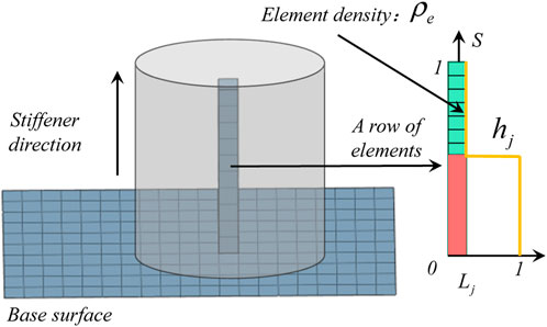
FIGURE 1. Illustration of the H-DGTP method.
According to the definitions provided earlier, the density of arbitrary element in the jth row of elements can be expressed as:
where
where
2.2 Minimum length scale control of the stiffener
Numerous length scale control methods have been proposed by researchers (Guest et al., 2004; Guest, 2008; Guest, 2009b; Wang et al., 2011; Zhang et al., 2014). Among them, an implicit length scale control approach commonly employed is density filtering with a projection, which can be traced back to the pioneering work of Guest (Guest et al., 2004). In this method, the projection threshold value is set to zero, and the minimum length is twice the filtering radius. Subsequently, Wang et al. (Sigmund, 2007; Wang et al., 2010) introduced a robust formulation to ensure stable optimization convergence, allowing for implicit length scale control when the eroded, intermediate, and dilated designs share the same topology. Numerical examples have demonstrated the effectiveness of this approach in generating visually pleasing and unambiguous 0–1 results, with precise control over the minimum length in both solid and void phases. As the H-DGTP method employs an individual design variable Lj, the robust formulation can be seamlessly applied in this study to achieve minimum length scale control for the stiffeners.
Following the idea in robust filtering approaches, design variable Li can be projected towards designs:
where the subscript * denotes d, i, and e, which means
where
with
The density of any one element in the jth row of elements is then modified as:
The design problem is formulated as a min/max problem:
where
where Ke is the (global level) element stiffness matrix of the solid element.
Qian et al. (Qian and Sigmund, 2013) derived the analytical formulas for predicting the minimal length scale bmin as a function of the projection threshold
It should be noted that in order to avoid confusion and facilitate reading, the parameters related to the minimum and maximum sizes are explained below:
It is worth noting here, for
2.3 Maximum length scale control of the stiffener
In actual topology optimization processes, when the load conditions are too simplistic or when excessive material usage is employed, it often leads to the accumulation of a significant amount of material in local regions. As a result, clear reinforcement structures cannot be obtained. To achieve a clear reinforcement structure, we introduce the topology structure maximum size constraint formulation proposed by Guest (Guest, 2009a).
The proposed maximum length scale constraint requires that the length scale all structural members be less than bmax. The scheme proposed here enforces this constraint by passing a circular test region
where
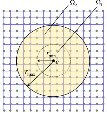
FIGURE 2. The test region of radius
Constraint (12) is reformulated in discretized form as:
where
To reduce the number of constraints, the maximum length control of the above equation can be condensed by the p-norm aggregation function:
where p is the index factor whose value is chosen as 100 in this paper.
The volume of voids measurement in the test region
where, the exponent q dictates the degree to which elements with intermediate volume fractions may count towards the volume of voids requirement, where
where
3 Numerical implementations
3.1 Sensitivity analysis
In order to apply the gradient-based solver to handle the topology optimization problem, the sensitivity of the compliance objective function with respect to Lj and hj can be calculated. Based on the chain rule, the sensitivity can be formulated as follows:
It is worth noting that
where
According to Eq. 2,
Finally, the sensitivity of the maximum size constraint function to the design variable is presented:
where
3.2 Flow chart
In order to explain the proposed algorithm process more clearly, we express it in the form of pseudocode as shown in Table 1.
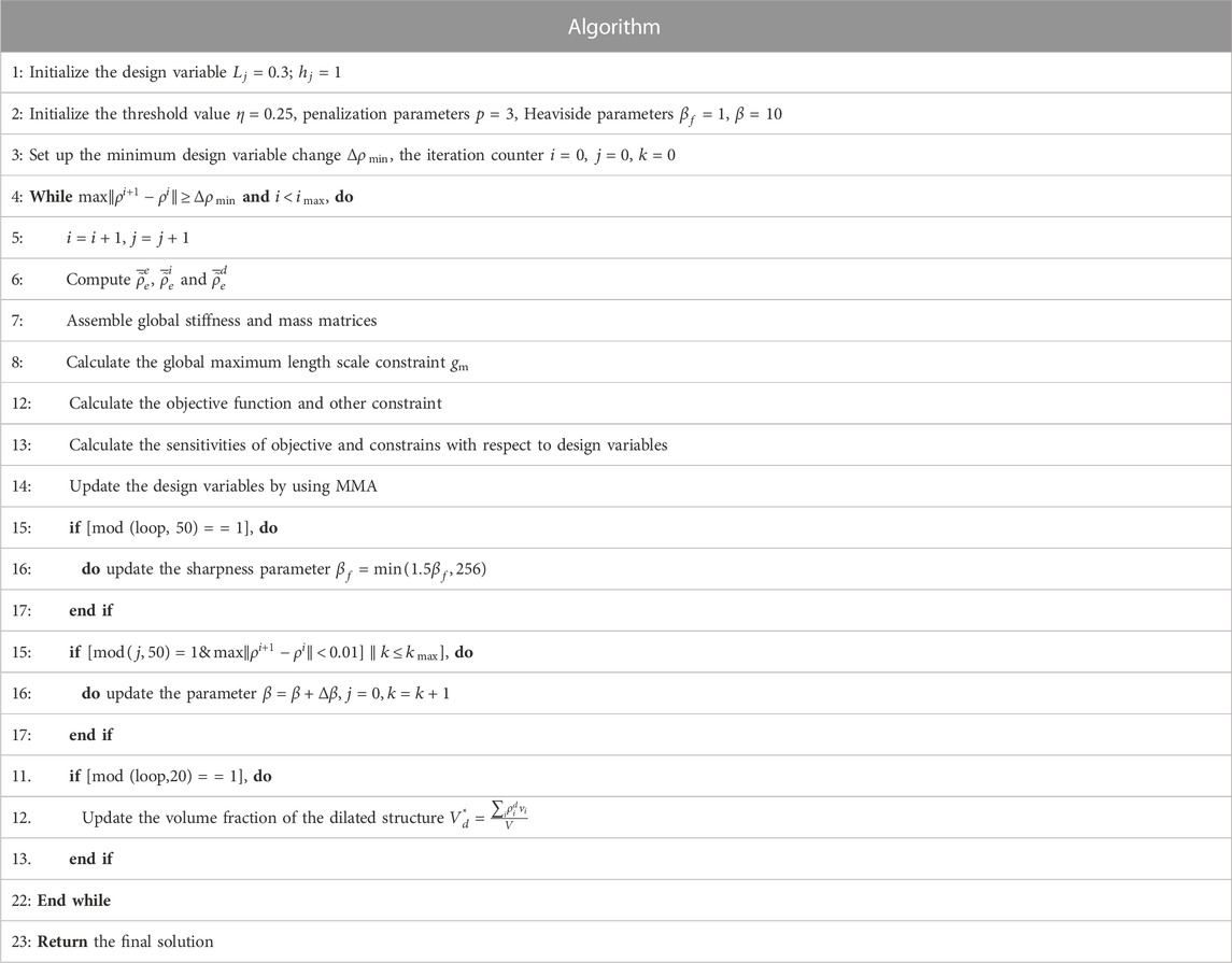
TABLE 1. Optimization flow chart.
It is worth noting that the counters i, k and j refer to iteration number, continuation step and iterations since last continuation steps, respectively. The number of different β value is given by kmax. In order to make the minimum length scale constraint easier to be implemented, a maximum size constraint is applied to the dilated field. In the intermediate design, the outer diameter bmax,i = bmax, inner diameter bmin,i = bmin of the annular test domain. For the dilated design, the outer diameter of the annular test area is bmax,d = bmax+0.6bmin, inner diameter is bmin,d = bmin+0.3bmin.
4 Numerical examples
Based on the above presented topology optimization method, numerical examples in three dimensions are presented. For all examples, the material of the structure is isotropic with Young’s modulus
4.1 Example 1: design of a simply supported plate
The first example is a simply-supported plate design problem. The dimensions and load/boundary conditions for the design domain are shown in Figure 3. The design domain is discretized by
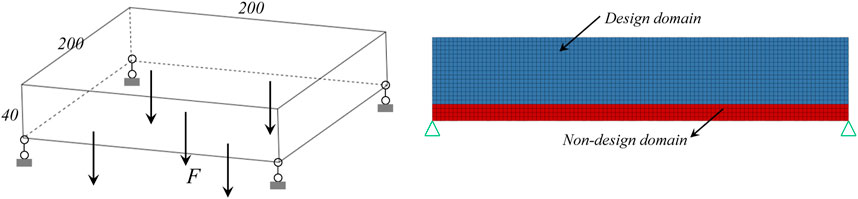
FIGURE 3. The design domain for the simply-supported plate design problem.
First, the design problem is optimized with different filter radius (rmin = 2,3,4,5,6,7), as shown in Figure 4. As can be seen, the proposed method successfully generates stiffener plate for all these examples, and besides, with the increase of filter radius, the minimum length scale gets bigger, demonstrating that the proposed method is capable of controlling the length scale of the optimized stiffener plate. Here it should be noted that the compliance gets larger, i.e., the structural performance becomes worse, when we use bigger filter radius. This is because the length scale constraint becomes stronger, and also the manufacturability gets better. Thus we should select a proper filter radius to balance the manufacturability and structural performance well when we use the proposed method in practice.
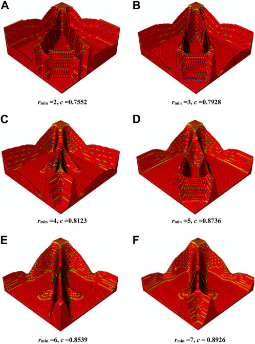
FIGURE 4. Optimized structure for different filtering radius.
As discussed above, different filtering radii result in different minimum size of the structure, and finally generate different topology optimization results. Due to the fact that the height field of the stiffener is also filtered with fully same filtering radius of the density field in the above results, the height of the optimized stiffener is gradient with a certain slope. Now, let us keep the density filtering radius fixed, i.e.,
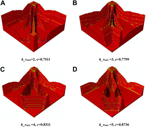
FIGURE 5. Optimized structure for different height filtering radius.
4.2 Example 2: design of a cantilever beam
In this section, we consider a design problem in 3D. The design domain shown in Figure 6 is a cuboid of size
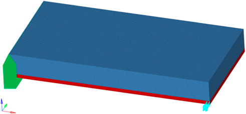
FIGURE 6. The design problem of 3D cantilever supported beam.
First, the robust formulation considering minimum length scale constraint is applied to solve this design problem with rmin = 2 and η = 0.25. In this example, the stiffener plate structures with uniform and gradient stiffener height are both considered. The optimized structures are shown in Figure 7 (a) and (b), respectively, and also, the design fields for case (b) are given in Figure 8. As can be seen from the results, the height for the optimized structures (a) and (b) are indeed uniform and gradient, which shows that the proposed method can generate structure with uniform or gradient stiffener.
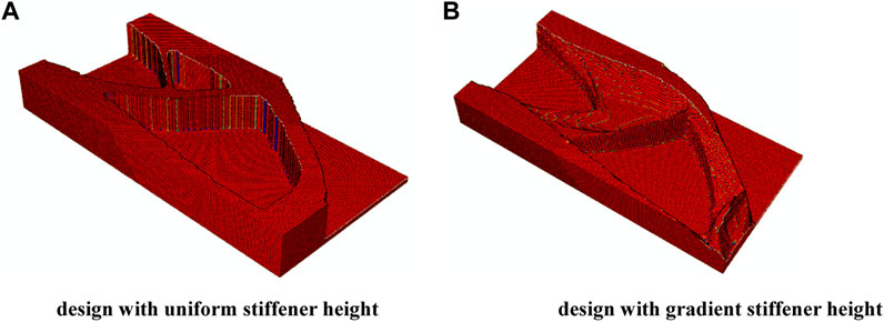
FIGURE 7. The stiffener plate design considering minimum length scale constraint with (A) uniform stiffener height (c = 2,826.5512), and (B) gradient stiffener height (c = 2,672.4581).

FIGURE 8. Design fields. (A) and (B) are the stiffener’s layout and height fields, respectively.
Now, let us consider the cases where the maximum and minimum length scale constraints are simultaneously applied for the design problem with equal height of stiffener. Figure 9 shows the results with maximum length scale constraint parameter rmax = 3.5, and with the minimum length scale constraint parameter rmin = 2. Here, (a) and (b) are the results when the maximum length scale constraint is applied on the dilated and intermediate fields, respectively. As can be seen, if the constraint is added to the dilated structure, the length scale of the void parts can also be controlled. Therefore, it is recommended to add the maximum length scale constraint to the dilated structure for the proposed method.
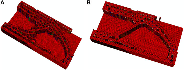
FIGURE 9. The designs with the maximum and minimum length scale constraints considered simultaneously, (A) the maximum length scale constraint is added to the dilated structure, c = 3642.6962; (B) the maximum length scale constraint is added to the intermediate structure, c = 3300.3941.
The influence of the lower and upper limits of length scale is studied for this example. First, the cases with rmin = 4 and rmax = 6.5 is provided for the equal-height stiffener, as shown in Figure 10 (b). Here for comparision, Figure 10 (a), i.e., the design without maximum length scale constraint, is also given. As can be seen, the minimum and maximum length scales become bigger compared to the result with rmin = 2 and rmax = 3.5, demonstrating the proposed method can control the length scales accurately. In addition, the cases with gradient-height stiffener when rmin = 4 and rmax = 6.5 are also given, as shown in Figure 11.
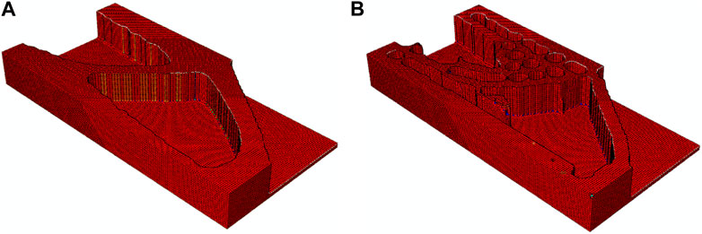
FIGURE 10. The design problem with rmin = 4 and rmax = 6.5 for the case with equal-height stiffener, (A) without maximum length scale constraint, c = 2,894.3987; (B) with maximum length scale constraint on dilated design, c = 3421.4256.
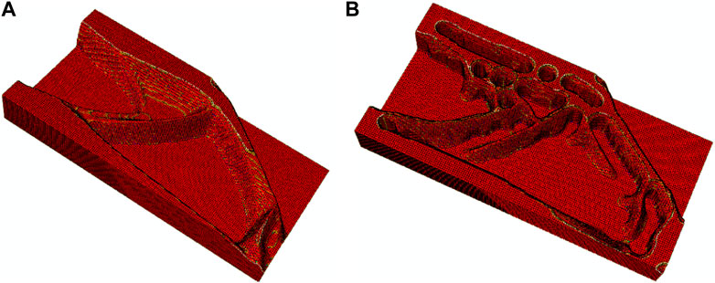
FIGURE 11. The design problem with rmin = 4 and rmax = 6.5 for the case with gradient-height stiffener, (A) without maximum length scale constraint, c = 2,719.2780; (B) with maximum length scale constraint on dilated design, c = 3402.4494.
5 Conclusion
In order to achieve an optimal layout for a clear reinforcement structure, this paper applies size control algorithms from topology optimization to the design of stiffeners. This allows for control over both the maximum and minimum sizes of the stiffeners, as well as the spacing between them. In the proposed method, the robust topology optimization formulation and a maximum length-scale constraint are introduced into the H-DGTP method, generating a new topology optimization method for the design of stiffener plate considering min-max length-scale constraint. Compared to existing methods, the proposed approach not only provides a clear layout of stiffeners, but also is capable of optimizing the stiffener’s height, and besides is capable of controlling the maximum and minimum length scales of the optimized structures. Specially, when the upper and lower length scales are set to be close, the thickness of the stiffeners can be optimized to be uniform, which better meets engineering requirements. Numerical examples show that the combination of the robust filter approach and maximum length scale constraint enables precise control of both structural features and gap widths, while effectively avoiding acute angles, demonstrating the effectiveness of the proposed method.
Data availability statement
The original contributions presented in the study are included in the article/supplementary material, further inquiries can be directed to the corresponding author.
Author contributions
SW: Writing–original draft, Writing–review and editing.
Funding
The author(s) declare that no financial support was received for the research, authorship, and/or publication of this article.
Conflict of interest
The author declares that the research was conducted in the absence of any commercial or financial relationships that could be construed as a potential conflict of interest.
Publisher’s note
All claims expressed in this article are solely those of the authors and do not necessarily represent those of their affiliated organizations, or those of the publisher, the editors and the reviewers. Any product that may be evaluated in this article, or claim that may be made by its manufacturer, is not guaranteed or endorsed by the publisher.
References
Allaire, G., Jouve, F., and Toader, A.-M. (2004). Structural optimization using sensitivity analysis and a level-set method. J. Comput. Phys. 194, 363–393. doi:10.1016/j.jcp.2003.09.032
Bendsøe, M., and Bendsoe, M. P. (1989). Optimal shape design as a material distribution problem. Struct. Optim. 1, 193–202. doi:10.1007/bf01650949
Bendsøe, M. P., and Kikuchi, N. (1988). Generating optimal topologies in structural design using a homogenization method. Comput. Methods Appl. Mech. Eng. 71, 197–224. doi:10.1016/0045-7825(88)90086-2
Bojczuk, D., and Szteleblak, W. (2008). Optimization of layout and shape of stiffeners in 2D structures. Comput. Struct. 86, 1436–1446. doi:10.1016/j.compstruc.2007.05.005
Cheng, K.-T., and Olhoff, N. (1981). An investigation concerning optimal design of solid elastic plates. Int. J. Solids Struct. 17, 305–323. doi:10.1016/0020-7683(81)90065-2
Descamps, B., and Coelho, R. F. (2014). The nominal force method for truss geometry and topology optimization incorporating stability considerations. Int. J. solids Struct. 51, 2390–2399. doi:10.1016/j.ijsolstr.2014.03.003
Ding, X., and Yamazaki, K. (2004). Stiffener layout design for plate structures by growing and branching tree model (application to vibration-proof design). Struct. Multidiscip. Optim. 26, 99–110. doi:10.1007/s00158-003-0309-4
Dong, X., Ding, X., Li, G., and Lewis, G. P. (2020). Stiffener layout optimization of plate and shell structures for buckling problem by adaptive growth method. Struct. Multidiscip. Optim. 61, 301–318. doi:10.1007/s00158-019-02361-0
Duan, Z., Yan, J., Lee, I., Wang, J., and Yu, T. (2018). Integrated design optimization of composite frames and materials for maximum fundamental frequency with continuous fiber winding angles. Acta Mech. Sin. 34, 1084–1094. doi:10.1007/s10409-018-0784-x
Dugré, A., Vadean, A., and Chaussée, J. (2016). Challenges of using topology optimization for the design of pressurized stiffened panels. Struct. Multidiscip. Optim. 53, 303–320. doi:10.1007/s00158-015-1321-1
Fernández, E., Yang, K.-k., Koppen, S., Alarcón, P., Bauduin, S., and Duysinx, P. (2020). Imposing minimum and maximum member size, minimum cavity size, and minimum separation distance between solid members in topology optimization. Comput. Methods Appl. Mech. Eng., 368.
Gea, H. C., and Luo, J. (1999). Automated optimal stiffener pattern design. Mech. Struct. Mach. 27, 275–292. doi:10.1080/08905459908915699
Gersborg, A. R., and Andreasen, C. S. (2011). An explicit parameterization for casting constraints in gradient driven topology optimization. Struct. Multidiscip. Optim. 44, 875–881. doi:10.1007/s00158-011-0632-0
Guest, J. K. (2008). Imposing maximum length scale in topology optimization. Struct. Multidiscip. Optim. 37, 463–473. doi:10.1007/s00158-008-0250-7
Guest, J. K. (2009a). Imposing maximum length scale in topology optimization. Struct. Multidiscip. Optim. 37, 463–473. doi:10.1007/s00158-008-0250-7
Guest, J. K., Prévost, J. H., and Belytschko, T. (2004). Achieving minimum length scale in topology optimization using nodal design variables and projection functions. Int. J. Numer. Methods Eng. 61, 238–254. doi:10.1002/nme.1064
Guest, J. K. (2009b). Topology optimization with multiple phase projection. Comput. Methods Appl. Mech. Eng. 199, 123–135. doi:10.1016/j.cma.2009.09.023
Guo, X., Zhang, W., and Zhong, W. (2014). Doing topology optimization explicitly and geometrically—a new moving morphable components based framework. J. Appl. Mech. 81. doi:10.1115/1.4027609
Hou, J., Zhu, J., He, F., Zhang, W., and Guo, W. (2017). Stiffeners layout design of thin-walled structures with constraints on multi-fastener joint loads. Chin. J. Aeronautics 30, 1441–1450. doi:10.1016/j.cja.2017.05.005
Li, Q., Qu, Y., Luo, Y., and Liu, S. (2021b). Concurrent topology optimization design of stiffener layout and cross-section for thin-walled structures. Acta Mech. Sin. 37, 472–481. doi:10.1007/s10409-020-01034-2
Li, Q., Wu, Q., Dou, S., Wang, J., Liu, S., and Chen, W. (2022). Nonlinear eigenvalue topology optimization for structures with frequency-dependent material properties. Mech. Syst. Signal Process. 170, 108835. doi:10.1016/j.ymssp.2022.108835
Li, Q., Xu, R., Wu, Q., and Liu, S. (2021a). Topology optimization design of quasi-periodic cellular structures based on erode–dilate operators. Comput. Methods Appl. Mech. Eng. 377, 113720. doi:10.1016/j.cma.2021.113720
Liu, S., Hu, R., Li, Q., Zhou, P., Dong, Z., and Kang, R. (2014). Topology optimization-based lightweight primary mirror design of a large-aperture space telescope. Appl. Opt. 53, 8318–8325. doi:10.1364/ao.53.008318
Liu, S., Li, Q., Chen, W., Hu, R., and Tong, L. (2015b). H-DGTP—A heaviside-function based directional growth topology parameterization for design optimization of stiffener layout and height of thin-walled structures. Struct. Multidiscip. Optim. 52, 903–913. doi:10.1007/s00158-015-1281-5
Liu, S., Li, Q., Chen, W., Tong, L., and Cheng, G. (2015a). An identification method for enclosed voids restriction in manufacturability design for additive manufacturing structures. Front. Mech. Eng. 10, 126–137. doi:10.1007/s11465-015-0340-3
Locatelli, D., Mulani, S. B., and Kapania, R. K. (2011). Wing-box weight optimization using curvilinear spars and ribs (SpaRibs). J. Aircr. 48, 1671–1684. doi:10.2514/1.c031336
Qian, X., and Sigmund, O. (2013). Topological design of electromechanical actuators with robustness toward over- and under-etching. Comput. Methods Appl. Mech. Eng. 253, 237–251. doi:10.1016/j.cma.2012.08.020
Rasmussen, J., Ansola, R., Canales, J., and Tarrago, J. A. (2004). Combined shape and reinforcement layout optimization of shell structures. Struct. Multidiscip. Optim. 27, 219–227. doi:10.1007/s00158-004-0399-7
Sigmund, O. (2007). Morphology-based black and white filters for topology optimization. Struct. Multidiscip. Optim. 33, 401–424. doi:10.1007/s00158-006-0087-x
Wang, F., Lazarov, B. S., and Sigmund, O. (2010). On projection methods, convergence and robust formulations in topology optimization. Struct. Multidiscip. Optim. 43, 767–784. doi:10.1007/s00158-010-0602-y
Wang, F., Lazarov, B. S., and Sigmund, O. (2011). On projection methods, convergence and robust formulations in topology optimization. Struct. Multidiscip. Optim. 43, 767–784. doi:10.1007/s00158-010-0602-y
Wang, M. Y., Wang, X., and Guo, D. (2003). A level set method for structural topology optimization. Comput. methods Appl. Mech. Eng. 192, 227–246. doi:10.1016/s0045-7825(02)00559-5
Xie, Y. M., and Steven, G. P. (1993). A simple evolutionary procedure for structural optimization. Comput. Struct. 49, 885–896. doi:10.1016/0045-7949(93)90035-c
Zhang, W., Zhong, W., and Guo, X. (2014). An explicit length scale control approach in SIMP-based topology optimization. Comput. Methods Appl. Mech. Eng. 282, 71–86. doi:10.1016/j.cma.2014.08.027
Zhang, W., Zhou, Y., and Zhu, J. (2017). A comprehensive study of feature definitions with solids and voids for topology optimization. Comput. Methods Appl. Mech. Eng. 325, 289–313. doi:10.1016/j.cma.2017.07.004
Zhou, M., and Rozvany, G. I. N. (1991). The COC algorithm, Part II: topological, geometrical and generalized shape optimization. Comput. Methods Appl. Mech. Eng. 89, 309–336. doi:10.1016/0045-7825(91)90046-9
Keywords: topology optimization, stiffener layout, maximum length-scale control, H-DGTP formulation, robust formulation
Citation: Wang S and Zhang H (2023) A new design method for stiffened plate based on topology optimization with min-max length-scale control. Front. Mater. 10:1277421. doi: 10.3389/fmats.2023.1277421
Received: 14 August 2023; Accepted: 26 September 2023;
Published: 10 October 2023.
Edited by:
Zhanyong Zhao, North University of China, ChinaCopyright © 2023 Wang and Zhang. This is an open-access article distributed under the terms of the Creative Commons Attribution License (CC BY). The use, distribution or reproduction in other forums is permitted, provided the original author(s) and the copyright owner(s) are credited and that the original publication in this journal is cited, in accordance with accepted academic practice. No use, distribution or reproduction is permitted which does not comply with these terms.
*Correspondence: Haibing Zhang, MzcxODE1NTRAcXEuY29t