 Geng Dang
 Cuixiang Pei
 Zhanfeng Yang1
95% of researchers rate our articles as excellent or good
Learn more about the work of our research integrity team to safeguard the quality of each article we publish.
Find out more
ORIGINAL RESEARCH article
Front. Mater. , 11 December 2023
Sec. Mechanics of Materials
Volume 10 - 2023 | https://doi.org/10.3389/fmats.2023.1273190
This article is part of the Research Topic Nondestructive Testing and Characterization of Solid Materials View all 6 articles
In this paper, a new and noncontact method with measuring longitudinal to shear wave velocity ratio by a dual-mode electromagnetic acoustic transducer is proposed for residual strain measurement in a metal structure without knowing its thickness. Firstly, the theoretical derivation of the ratio of longitudinal and shear wave velocities in electromagnetic ultrasound was conducted, and based on this, the effectiveness of the dual-mode bulk wave electromagnetic acoustic transducer was simulated. Secondly, the longitudinal and shear wave velocities of uniaxial stretched aluminum plates with different residual strains were measured using the established electromagnetic ultrasound experimental system. Finally, the ratio of longitudinal and shear wave velocities of specimens with different plastic deformations was analyzed, achieving quantitative non-destructive testing of residual strain in uniaxial tensile aluminum plates.
When engineering materials and components are loaded, residual plastic strain can affect the physical and chemical properties of metal, making the performance of metal anisotropic (Chen et al., 2010). Residual strain makes the internal deformation of metal uneven, dislocation, vacancy and other Crystallographic defect increase, and residual internal stress will be generated in the metal (Hanlon et al., 2001). Residual internal stress will reduce the corrosion resistance of metal, and in serious cases, it can lead to deformation or cracking of parts. The above have quality problems during the engineering use process, and even lead to many quality accidents in severe cases. Therefore, nondestructive testing and evaluation of residual strain in metal structures is very important.
The traditional detection methods of residual strain include X-ray diffraction (XRD), Ultrasonic testing (UT) and other online detection methods. However, these detection methods may have certain problems in practical applications, such as the difficulty of XRD for on-site inspection, and it may lead to some radiation safety issues. The UT can be applied with the conventional contact piezoelectric transducers (PZTs) and the new electromagnetic acoustic transducers (EMATs). Compared with conventional PZTs, EMATs use electromagnetic coupling method to excite and receive ultrasonic waves. EMATs have the advantages of high precision, no need of couplant, non-contact, suitable for high temperature testing and easy to excite various ultrasonic shapes (Hosten et al., 1996; Chotard et al., 2001; Wang et al., 2012; Zhai et al., 2013). At present, it has been widely used in the field of nondestructive testing of materials. Until now, most of UT methods for residual stress or strain measurement are based on the effect of acoustoelasticity. The acoustoelastic effect is related to the change of ultrasonic wave speed with residual stress or strain. The advantage of the UT method is the simple operation and wide applicability. However, the exact value of the travelling distance of ultrasonic wave, which is the twice of the thickness of the specimen for pulse-echo measurement, should be measured or known to precisely measure the ultrasonic wave speed. That is usually impossible for the onsite inspection.
In this work, a new UT method with measuring longitudinal to shear wave velocity ratio (LSWVR) with a dual-mode EMAT is proposed for residual strain measurement. The main advantage of this method is that it can provide a noncontact and rapid measurement method for residual strain measurement inside of a metal structure without know its thickness. Firstly, a bulk wave based electromagnetic ultrasonic residual strain measurement method for metal materials was proposed; Secondly, the developed dual-mode electromagnetic acoustic transducer (EMAT) is used to measure longitudinal and shear wave velocities of different residual strains in uniaxial stretched aluminum plates (Zhai et al., 2022). Finally, the relationship between different plastic deformation amplitudes and LSWVR was analyzed, and quantitative non-destructive testing of residual strain in uniaxial tensile aluminum plates was achieved (Hikata et al., 1963; Mak and Gauthier, 1993; Zaretsky and Kanel, 2012).
According to the acoustic elastic effect, the velocity of ultrasonic waves would vary with stress or strain in materials, and the rate of change in ultrasonic wave velocity is proportional to strain or stress (JOHSON, 1981; RAVI-CHANDAR, 1993):
In the formula,
Based on this formula, the relationship between the LSWVR can be derived, as shown in Equation 3:
Therefore, according to Equation 3, there is a certain relationship between the LSWVR.
Based on the above theory, the LSWVR of materials is analyzed. Generally, the measurement of material wave velocities is mainly through the pulse-echo wave method to detect the propagation of ultrasonic waves inside the specimen. The pulse-echo wave method obtains the velocity of L wave and S wave of materials by measuring the propagation time and distance of L and S waves in block solids. As shown in Figure 1, the propagation of L and S waves in the specimen is characterized. By measuring the thickness of the test piece and the propagation time of the L wave in it, the L wave velocity of the test piece is obtained. By measuring the thickness of the test piece and the propagation time of the S wave in it, the S wave velocity of the test piece is obtained. The propagation of sound waves from the incident surface to the reflecting surface and back to the incident surface is called a complete path propagation, which is twice the thickness of the test piece.
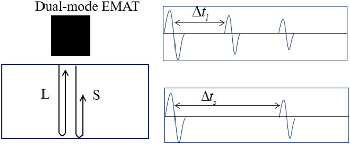
FIGURE 1. Schematic diagram of longitudinal and shear wave propagation.
Therefore, the relationship between the L and S waves, the thickness of the specimen, and the time difference between the two echoes obtained is:
Where
By combining formulas 4 and 5, the relationship between the LSWVR and the average value of multiple echo time differences can be obtained, as follows:
Therefore, the value of LSWVR is just the ratio of the pulse echo time of S wave and L wave. It is independent of the specimen thickness.
Since the existing bulk wave EMAT can only excite and receive single mode waveform, and mainly S wave, it is very necessary to develop dual-mode EMAT. The developed dual-mode EMAT consists of a rectangular magnet group with multiple magnetic poles facing each other and a double-layer meander-line coil. As shown in Figure 2, the bulk wave transducer magnet configuration consists of multiple rectangular magnet groups with the same magnetic poles arranged face-to-face. The magnetic field lines are emitted from the N poles of the two magnets arranged face-to-face, passing through their gaps and returning to their adjacent S poles. A high-strength horizontal magnetic field is formed directly below the magnet, which is alternately arranged on the left and right sides, and a high-strength radial magnetic field is formed between multiple magnets, which is vertically arranged on the surface of the test piece. Both layers of coils adopt a meander-line coil, with one meander-line coil fixed below the magnet, the coil conductor part located directly below the magnet, and the coil gap facing the magnet group gap. The other meander-line coil conductor part located in the magnet gap, and the coil gap located directly below the magnet group. Two meander-line coils are interleaved to achieve efficient excitation and reception of L and S waves, respectively.
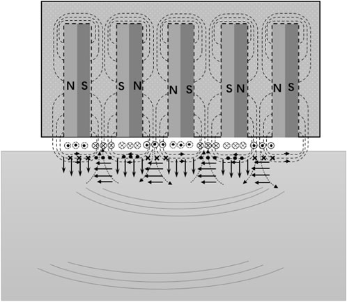
FIGURE 2. Structure of dual-mode EMAT
The generation process of S and L waves in general non ferromagnetic specimens is also based on the Lorentz force mechanism. When two coils are respectively connected with pulse current, the alternating Eddy current is induced on the near surface of the test piece, which interacts with the horizontal magnetic field to form a Lorentz force perpendicular to the surface of the test piece and in the same direction, thus realizing the efficient excitation of ultrasonic L waves in the test piece. The interaction with a vertical magnetic field forms a Lorentz force parallel to the surface of the specimen and in the same direction, thereby achieving efficient excitation of ultrasonic S waves. The reception of L and S waves is exactly the opposite process.
According to the structure of the dual-mode bulk wave EMAT introduced, in order to study the performance of the dual mode bulk wave EMAT, the dual-mode EMAT is analyzed to detect signals of L and S waves. To simplify the calculation process, the actual three-dimensional model is simplified into a two-dimensional finite element calculation model in the numerical simulation process. The length of the simplified model is 120 mm, and the height is 30 mm. The material is aluminum, and the density is ρ is
Due to the strong horizontal magnetic field generated directly below the multiple magnets of the dual-mode bulk wave EMAT, it can be observed from Figure 3A that the developed dual-mode EMAT can successfully excite L waves when the meander-line coil placed directly below the multiple magnets is energized. Due to the vertical magnetic field generated between multiple magnets in a dual-mode bulk wave, it can be observed from Figure 3B that the developed dual-mode EMAT can successfully excite S waves when the coil placed between the magnets is energized. Therefore, this indicates that the developed dual-mode EMAT can successfully excite L and S waves. Figure 4 shows the waveform of vibration velocity signals of particles on the surface of aluminum blocks in the x-z direction under the action of L and S waves when two meander-line coil EMATs are respectively energized. The 1L, 2L and 1S indicate the first and second echo of the longitudinal wave and shear wave. Therefore, the simulation results can well prove that the developed dual-mode bulk wave EMAT can successfully excite and receive L and S wave signals.
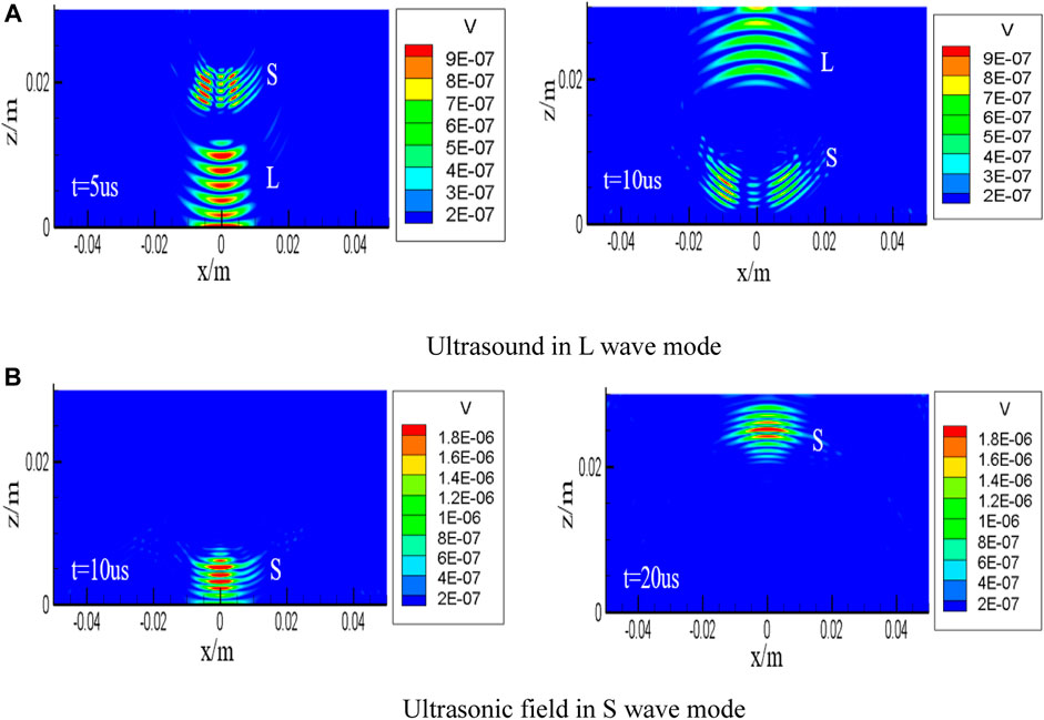
FIGURE 3. Simulated ultrasound fields of two waveforms on the x-z plane (A) L wave waveform (B) S wave waveform.
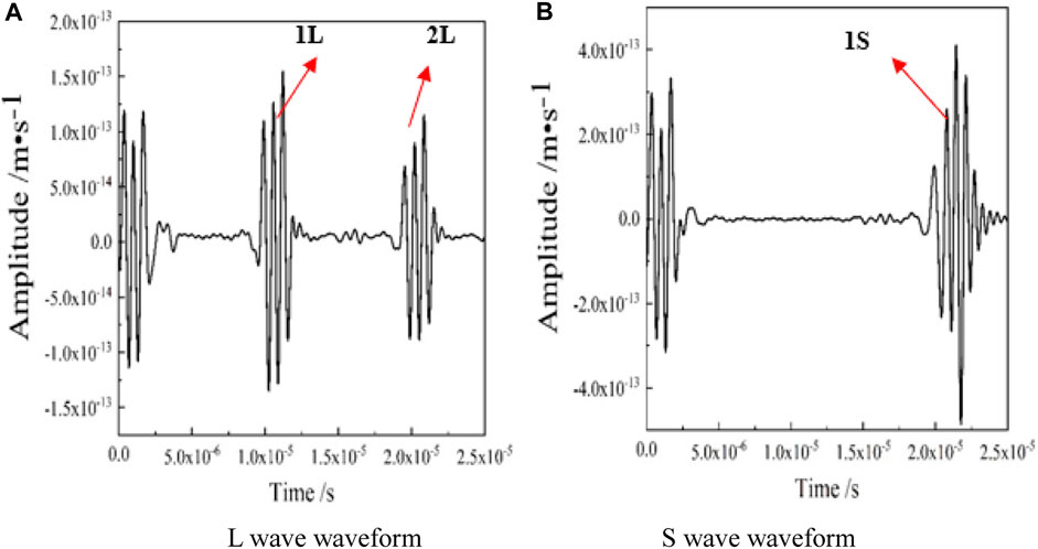
FIGURE 4. Ultrasonic waveform produced by dual-mode bulk wave EMAT.
By constructing an experimental system based on the proposed method for plastic deformation measurement, the dual mode wave EMAT was experimentally verified and the residual strain of the sample was measured, as shown in Figure 5. The experimental system includes a signal pulser and receiver (RAM-5000), a computer with built-in software, a bandpass filter, an oscilloscope, and a self-made integrated L and S wave EMAT. During the experiment, the signal pulser and receiver provides pulse excitation current, and the transducer that receives the pulse current will excite a L or S wave signal in the specimen. This signal is received by the self-excited self-test transducer, filtered by a filter, and then passed into the oscilloscope to achieve the detection of L and S wave signals.
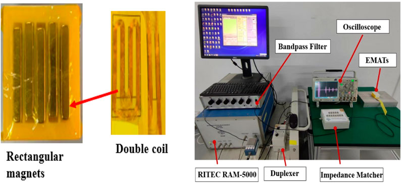
FIGURE 5. The dual-mode EMAT and corresponding experimental measurement system.
In order to perform non-destructive evaluation on the measurement of residual strain wave velocity in metals, tensile aluminum plate specimens were used and stretched on an MTS uniaxial tensile machine as shown in Figure 6. In order to make the deformation of plastic deformation micro damage specimens more accurate, it is necessary to monitor the real-time situation of uniaxial tensile aluminum plates. The usual method we use is to use an extensometer on the axis of the residual strain specimen surface. The material used for the uniaxial specimen is 1,060 aluminum plate, as this material contains 99.6% aluminum and has high tensile strength. The uniaxial untensioned specimen exhibits a dog bone shape with a thickness of 6.10 mm. Figure 6 shows the plastic deformation aluminum plate specimen pulled on the MTS stretching machine. The loading direction of the tensile specimen is parallel to the rolling direction of the specimen, and 7 specimens, including the reference specimen, have plastic deformation ranging from 0% to 5.6%. Table 1 shows the thickness of the middle area of the 7 tensile specimens.
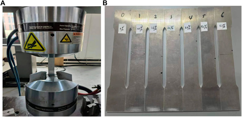
FIGURE 6. Tensile test: test setup (A) and specimen with different residual plastic strain after tensile test (B).
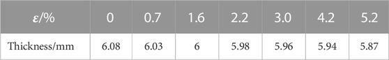
TABLE 1. Residual strain and thickness of stretched aluminum sheet after plastic deformation.
Based on the theoretical methods and principles introduced in Section 2.1, this section will study the evaluation method of electromagnetic ultrasonic residual strain of metal materials based on the longitudinal/shear wave velocity ratio (LSWVR) in experiments. The developed dual-mode bulk wave EMAT is used to measure the velocity of L wave and T wave in the stretched aluminum plates with different residual strains. The relationship between different residual strain sizes and the LSWVR is analyzed. Figure 7 shows the L and S wave signals measured on an aluminum plate without strain using a dual-mode bulk wave EMAT. Multiple echo signals in Figure 7 were measured by this EMAT. It can be observed that the arriving time of the first echo in the experiment signals is not normal. This is due to the device software issues. It also can be observed that the amplitude of S wave is more than twice of the amplitude of L wave generated by this EMAT. This is consistent with the numerical simulation results as shown in Figure 4. The velocity of L wave and T wave in the stretched aluminum plates was calculated using the acoustic time difference method according to Equations 4, 5.
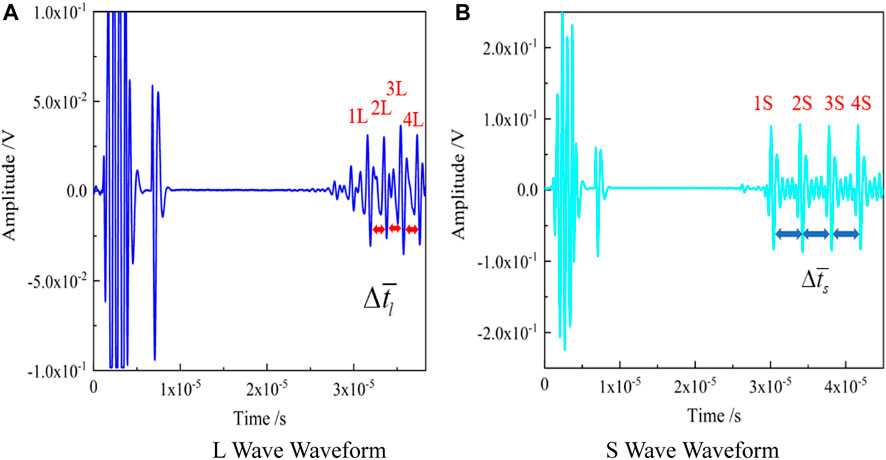
FIGURE 7. Measurement signals with the dual-mode EMAT.
The L and S wave waveforms of specimens with different residual strain damage were measured using dual-mode EMAT. The relationship between the velocity of L wave and T wave in the stretched aluminum plates with different residual strains was obtained by combining formulas 4 and 5, as well as Table 1. Figure 8 shows the relationship between L wave velocity and different residual strains in the stretched aluminum plates, as well as the relationship between S wave velocity and different residual strains in the stretched aluminum plates. From Figure 8, it can be seen that as residual strain increases, both the velocity of L wave and S wave decrease gradually. The reason for the L wave and S wave velocities decreasing gradually as residual strain increases mainly due to the small change of the elastic modulus of the materials under strain or stress.
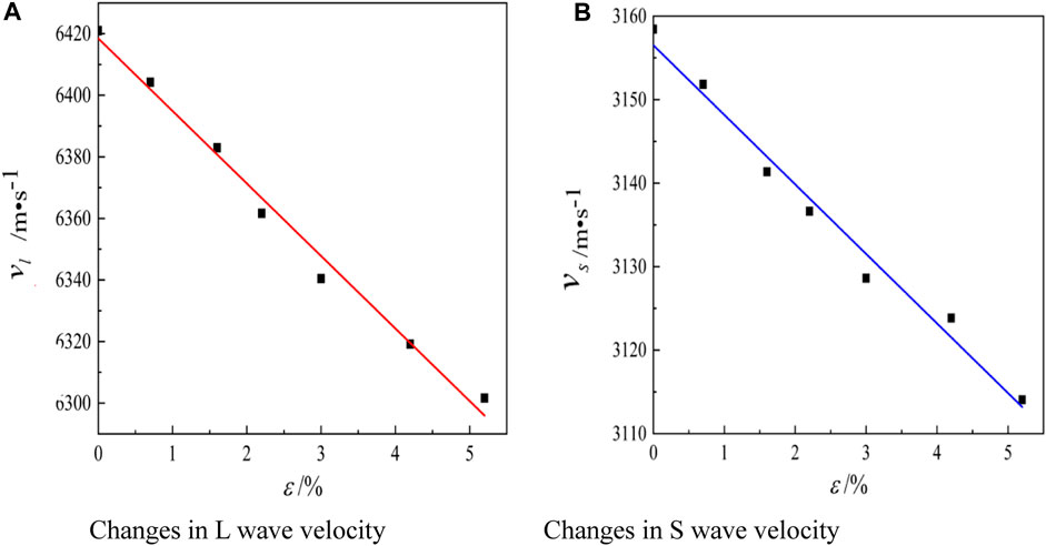
FIGURE 8. The relationship between the changes in wave velocity and residual plastic strain.
Although the velocity of L wave and T wave are linearly related to the residual strain specimen, accurate values need to be calculated by knowing the thickness value of the specimen. However, in practical complex on-site applications, due to residual strain and other damages occurring during long-term service of the material, as well as the complexity of the material itself, it is impossible to obtain its true thickness value. Therefore, it is necessary to conduct calibration free measurement on complex structures. Therefore, we can obtain the relationship between the LSWVR and the residual strain of stretched aluminum plates through formula 6. As shown in Figure 9, there is also a linear relationship between the residual plastic strain and the LSWVR. Therefore, it indicates that quantitative non-destructive testing of residual strain without measuring and knowing the thickness of the specimens can be achieved.
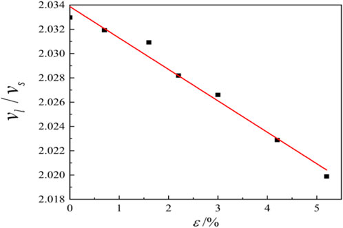
FIGURE 9. Relationship between the LSWVR and residual plastic strain.
A new and noncontact method with measuring LSWVR by a dual-mode EMAT is proposed and developed for residual plastic strain measurement in a metal structure without knowing its thickness. A dual-mode EMAT that for generating and detecting both L and S waves is developed firstly. Then experimental measurements were conducted on uniaxial tensile specimens with different residual plastic strains using the developed dual mode EMAT. The measurement results verified that there is a linear relationship between residual strain and the LSWVR. Therefore, the quantitative non-destructive testing of residual strain without measuring and knowing the thickness of the specimens can be achieved.
The original contributions presented in the study are included in the article/Supplementary material, further inquiries can be directed to the corresponding authors.
GD: Data curation, Investigation, Writing–original draft. CP: Writing–original draft, Writing–review and editing. ZY: Writing–review and editing. HZ: Investigation, Writing–review and editing.
The author(s) declare that no financial support was received for the research, authorship, and/or publication of this article.
The authors would like to thank the National Key R&D Project for Young Scientists (No. 2022YFB3707202), National Natural Science Foundation (No. 12072255, No. 11927801) for funding.
The authors declare that the research was conducted in the absence of any commercial or financial relationships that could be construed as a potential conflict of interest.
All claims expressed in this article are solely those of the authors and do not necessarily represent those of their affiliated organizations, or those of the publisher, the editors and the reviewers. Any product that may be evaluated in this article, or claim that may be made by its manufacturer, is not guaranteed or endorsed by the publisher.
Chen, J., Zhang, Y., He, J. P., Yao, K. F., Wei, B. C., and Chen, G. L. (2006). Metallographic analysis of Cu–Zr–Al bulk amorphous alloys with yttrium addition. Scr. Mater. 54, 1351–1355. doi:10.1016/j.scriptamat.2005.12.002
Chen, W. W., Zhou, K., Keer, L. M., and Wang, Q. J. (2010). Modeling elasto-plastic indentation on layered materials using the equivalent inclusion method. Int. J. Solids Struct. 47 (20), 2841–2854. doi:10.1016/j.ijsolstr.2010.06.011
Chotard, T., Gimet-Breart, N., Smith, A., Fargeot, D., Bonnet, J., and Gault, C. (2001). Application of ultrasonic testing to describe the hydration of calcium aluminate cement at the early age. Cem. Concr. Res. 31 (3), 405–412. doi:10.1016/s0008-8846(00)00446-4
Duqennoy, M., Ouaftouh, M., and Ourak, M. (1999). Determination of stresses in aluminium alloy using optical detection of Rayleigh waves. Ultrasonics 37 (5), 365–372. doi:10.1016/s0041-624x(99)00009-8
Hanlon, D., Sietsma, N. J. S., and Zwaag, V. D. (2001). The effect of plastic deformation of austenite on the kinetics of subsequent ferrite formation. Trans. Iron Steel Inst. Jpn. 41 (9), 1028–1036. doi:10.2355/isijinternational.41.1028
Hikata, A., Chick, B. B., and Elbaum, C. (1963). Effect of dislocations on finite amplitude ultrasonic waves in aluminum. Appl. Phys. Lett. 3 (11), 195–197. doi:10.1063/1.1753845
Hosten, B., Hutchins, D. A., and Schindel, D. W. (1996). Measurement of elastic constants in composite materials using air-coupled ultrasonic bulk waves. J. Acoust. Soc. Am. 99 (4), 2116–2123. doi:10.1121/1.415398
Johson, G. C. (1981). Acoustoelastic theory for elastic plastic materials. J. Acoust. Soc. Am. 70, 591–595. doi:10.1121/1.386748
Mak, D., and Gauthier, K. J. (1993). Ultrasonic measurement of longitudinal and shear velocities of materials at elevated temperatures. Ultrasonics 31 (4), 245–249. doi:10.1016/0041-624X(93)90017-T
Novelo-Peralta, O., González, G., and Lara-Rodríguez, G. A. (2008). Characterization of precipitation in Al–Mg–Cu alloys by X-ray diffraction peak broadening analysis. Mater. Charact. 59, 773–780. doi:10.1016/j.matchar.2007.06.012
Ravi-Chandar, K. (1993). Progration of ultrasonic plane waves in a plastically deformed medium. Rev. Prog. Quantitative Nondestruct. Eval. 12, 2083–2089.
Wang, S., Li, Z., Lei, K., Xiaoguang, H., and Xiao, Z. (2012). “Modeling and comparison of three bulk wave EMATs,” in IECON 2011 - 37th Annual Conference of the IEEE Industrial Electronics Society, Melbourne, VIC, Australia, 07-10 November 2011.
Zaretsky, E. B., and Kanel, G. I. (2012). Effect of temperature, strain, and strain rate on the flow stress of aluminum under shock-wave compression. J. Appl. Phys. 112 (7), 073504. doi:10.1063/1.4755792
Zhai, G., Liang, B., Li, X., Ge, Y., and Wang, S. (2022). High-temperature EMAT with double-coil configuration generates shear and longitudinal wave modes in paramagnetic steel. NDT E Int. Indep. Nondestruct. Test. Eval. 125, 102572. doi:10.1016/j.ndteint.2021.102572
Keywords: electromagnetic acoustic transducer, residual strain, longitudinal wave, shear wave, velocity
Citation: Dang G, Pei C, Yang Z and Zhou H (2023) Residual strain measurement based on longitudinal to shear wave velocity ratio with a dual-mode EMAT. Front. Mater. 10:1273190. doi: 10.3389/fmats.2023.1273190
Received: 05 August 2023; Accepted: 13 November 2023;
Published: 11 December 2023.
Edited by:
Geoffrey Robert Mitchell, Polytechnic Institute of Leiria, PortugalReviewed by:
Yan Lyu, Beijing University of Technology, ChinaCopyright © 2023 Dang, Pei, Yang and Zhou. This is an open-access article distributed under the terms of the Creative Commons Attribution License (CC BY). The use, distribution or reproduction in other forums is permitted, provided the original author(s) and the copyright owner(s) are credited and that the original publication in this journal is cited, in accordance with accepted academic practice. No use, distribution or reproduction is permitted which does not comply with these terms.
*Correspondence: Cuixiang Pei, cGVpLmN4QG1haWwueGp0dS5lZHUuY24=; Haiqiang Zhou, aGFpcWlhbmcwNjAyQDEyNi5jb20=
Disclaimer: All claims expressed in this article are solely those of the authors and do not necessarily represent those of their affiliated organizations, or those of the publisher, the editors and the reviewers. Any product that may be evaluated in this article or claim that may be made by its manufacturer is not guaranteed or endorsed by the publisher.
Research integrity at Frontiers
Learn more about the work of our research integrity team to safeguard the quality of each article we publish.