
95% of researchers rate our articles as excellent or good
Learn more about the work of our research integrity team to safeguard the quality of each article we publish.
Find out more
ORIGINAL RESEARCH article
Front. Mater. , 06 October 2023
Sec. Energy Materials
Volume 10 - 2023 | https://doi.org/10.3389/fmats.2023.1258382
 Melinda R. Hoyt1
 Gillian I. Falcon2Charles J. Pearce1Robert E. Delaney1
 Tyler E. Stevens1Emily M. Johnson3Thomas M. Szenderski4Nathan R. Sorenson1
 Sydney F. Fultz-Waters5
 Mark A. Rodriguez1
 Lisa J. Whalen1
 Todd C. Monson1*
Soft magnetic composites (SMCs) offer a promising alternative to electrical steels and soft ferrites in high performance motors and power electronics. They are ideal for incorporation into passive electronic components such as inductors and transformers, which require a non-permanent magnetic core to rapidly switch magnetization. As a result, there is a need for materials with the right combination of low coercivity, low magnetic remanence, high relative permeability, and high saturation magnetization to achieve these goals. Iron nitride is an attractive soft magnetic material for incorporation into an amine/epoxy resin matrix. This permits the synthesis of net-shaped SMCs using a “bottom-up” approach for overcoming the limitations of current state-of-the-art SMCs made via conventional powder metal processing techniques. In this work we present the fabrication of various net-shaped, iron nitride-based SMCs using two different amine/epoxy resin systems and their magnetic characterization. The maximum volume loading of iron nitride reached was ∼77% via hot pressing, which produced SMCs with a saturation magnetic polarization (Js) of ∼0.9 T, roughly 2–3 times the Js of soft ferrites.
Soft magnetic composites (SMCs) are composed of micro- or nanometer-sized particles of a soft magnetic material coated with an insulating binder, which are then consolidated at high pressure or incorporated into a matrix (Shokrollahi, 2007; Périgo, 2018; Silveyra, 2018). They offer a promising alternative to both costly rare earth permanent magnets and electrical steels and soft ferrites in both motors (Guo, 2023) and power electronics (Rodriguez-Sotelo, 2020). The isotropic nature of SMCs is ideally suited for use in rotating electrical machines. However, standard soft magnetic materials do not perform efficiently in motors reaching rotational speeds of over 20,000 rpm. At high rotational speed, standard soft magnets lose energy to eddy currents due to material conductivity. Silicon steel exemplifies this behavior as a conductive soft magnetic material but still finds wide application. Alternatively, high performing motors can be made using rare earth permanent magnets, but they do not meet the US Drive Electronics and Electrical Technology Team goal to reduce the cost of electric drive motors to $3.3/kW by 2025 (“Electrical and Electronics Technical Team Roadmap” 2017). Barriers to the reduction of cost include size, weight, and power requirements for motor components as well as the cost of raw materials. The manufacturing cost of SMCs is low and they are highly amenable to advanced manufacturing and net-shaping into complex geometries, which further reduces manufacturing costs. SMCs are ideal materials for incorporation into passive components of power electronics such as inductors (Sugawa, 2013; Yun, 2016; Yan, 2017), which require a soft magnetic core to reach high power densities (Silveyra, 2018). These components must rapidly switch magnetization in order to increase the performance and store more energy in the form of magnetic flux density. In these situations, low electrical losses, low Hc (coercivity, <1000 A/m), low Mr (magnetic remanence), high µr (relative permeability) and high Ms (saturation magnetization) are desired. As Ms increases, the maximum field at which the device can operate increases, which in turn can have a positive impact on the size, weight and power of the component required for the device, since large Ms values allow miniaturization. Currently available soft magnetic materials are unable to meet these needs, so there is still significant room for advancement in SMCs, and therefore additional improvements in electrical machine performance to be realized. Using a bottom-up approach in which the soft magnetic material is first milled with the amine component of the composite, then cross-linked with the epoxy component, results in custom functionalization of the particles. The composite is then fabricated in a variety of geometries as opposed to relying on conventional pressing techniques limited in size and shape. Our final objective is to create SMCs with high magnetic material loading (and therefore high Ms) and improved magnetic properties over current state-of-the-art SMCs.
Soft magnetic composites avoid the eddy current losses seen with standard soft magnetic materials by means of an insulating matrix which increases resistivity, but this comes at the expense of μr and Ms as the volume fraction of soft magnetic material decreases or distance between magnetic domains increases. Phase separation and aggregation can lead to heterogeneity in matrixed systems and degrade performance, which can be avoided with matrix-free systems (Watt, 2018). Matrix-free composites are synthesized by covalently attaching a functional group to the surface of the particle, then cross-linking the particles together through formation of another covalent bond. Examples of reactions that have been used to make matrix-free nanocomposites include a 1,3-dipolar cycloaddition between an azide and an alkyne (Dach, 2010), and nucleophilic addition of an amine to an epoxide (Mochalin, 2011; Watt, 2018; Li, 2022). Matrix-free nanocomposites also have shown improved strength and toughness (Mochalin, 2011) in addition to a higher weight percent of FeO/FexOy nanoparticles (Watt, 2018). On the other hand, polymer matrices vary in their thermal and physical properties and are cost-effective, lightweight, easily synthesized and numerous types are commercially available. Combining these options with the variety of commercially available soft magnetic materials, it is possible to tune soft magnetic composites for a variety of mechanical, magnetic and electrical properties. It is critical to find the balance between minimizing cost, maximizing soft magnetic material loading, ease of processing and desired magnetic properties of SMCs for specific applications.
A typical soft magnetic material is either ferrimagnetic (often ceramic oxides) or ferromagnetic (based on iron or nickel), with an inorganic or organic coating (Poškovic, 2021). Inorganic coatings can be metallic oxides, phosphates, and sulfates. Organic coatings are either thermoplastic or thermoset polymers (amine/epoxy resins, acrylics, polyesters, polyurethanes or epoxy/polyester hybrids). For example, iron-based SMCs have been fabricated with a mixture of pure iron powder and resin, pure iron powder with additives like zinc stearate and carbon, and powder alloys of iron, nickel, cobalt, and silicon (Shokrollahi, 2007). The insulating matrix surrounds and separates magnetic particles and lends overall increased electrical resistivity. Most of the iron powder-based SMCs developed to date have electrical resistivities over a wide range of 0.1–1,200 µΩ*m, (Lefebvre, 1997; Taghvaei, 2009; Kollar, 2013), in most cases greater than the resistivity of 3% silicon steel (∼0.5 µΩ*m) (“Super Core™ Electrical steel sheets for high-frequency application” 2017; Coey, 2010). However, with a few exceptions in the range of 105–1011 μΩ*m (Zhu, 2011), the electrical resistivity of most SMCs remains well below the 10–108 μΩ*m resistivities seen in NiZn(“Nickel Zinc Ferrite Materials”, 2023) and MnZn('Mn-Zn Ferrite Material characteristics', 2022) ferrites.
Epoxy resins (Jin, 2015) adopt a net-shaped geometry while curing, which facilitates their implementation in high performance motors or power electronics. The complex geometries possible with epoxy-resin based composites reduce the manufacturing cost of the final soft magnetic motor component beyond what is already achievable by avoiding the use of permanent magnets containing rare earth metals. Further, epoxy composites are intrinsically isotropic, making them useful for motors and other applications with 3D flux paths. Researchers have already demonstrated the feasibility of using epoxy resins in the design of electrical machinery (“New structural adhesive from Delo for magnet bonding has high temperature stability” 2019; Electric Motor Products’ Sugawa, 2013) and in 3D printing of magnetic materials (Zhang, 2021; Wei, 2022). Epoxy resin systems are also capable of exceeding the 150°C minimum Tg required for operation in electric motors and drives, as magnets are expected to function in temperatures this high in power electronics. (“Electrical and Electronics Technical Team Roadmap” 2017) Finally, epoxy resin composites have been shown to perform well at rotational speeds of up to 60,000 rpm in flywheels and high speed motors (Mason, 1999; Schoppa, 2014).
Iron nitride is an attractive magnetic powder for making epoxy composites that overcome the limitations of standard SMCs, as well as being composed of the abundant elements iron and nitrogen (Coey, 1999; Bhattacharyya, 2015; Zhang, 2018). In the γ′-Fe4N phase, iron nitride sheets have an electrical resistivity (ρ) of 1.62 μΩ*m and a saturation magnetic polarization (Js, where Js = μ0Ms) of ∼1.8 T (Chen, 1991), slightly less than the ∼2 T saturation magnetization of silicon steel (Coey, 2010; 'Super Core™ Electrical steel sheets for high-frequency application’ 2017). Commercially available iron nitride is supplied as a mixture of Fe3-4N ('Iron nitride certificate of analysis, Catalog No. 088198.22' 2022), but it is possible to anneal the mixed powder at high temperature to obtain ∼95% γ′-Fe4N powder. Epoxy composites prepared with a high volumetric loading of γ′-Fe4N phase iron nitride should therefore have high saturation magnetic polarization, while also having the potential for electrical resistivities higher than standard SMCs. Additionally, the iron nitride-based epoxy composites should show low eddy current loss if good particle separation is achieved. While only a matrix-free system will guarantee particle separation, some separation is possible by first coating the iron nitride powder with a diamine curing agent. The amine then crosslinks with the epoxide to create the cured composite. Selecting our own epoxy monomers allows us to design our composites in unique shapes from the ground up and tailor their properties, in contrast to methods using conventional powder metal processing techniques that introduce internal mechanical stress. With these goals in mind, one amine curing agent (Figure 1, 4-aminophenyl sulfone) and two epoxy resins (Figure 1, trimethylolpropane triglycidyl ether and N,N-diglycidyl-4-glycidyloxyaniline), were selected and first evaluated for their cure chemistry. Once the chemistry of the amine/epoxy systems was firmly established, neat, cured samples were characterized by both thermogravimetric analysis (TGA) and differential scanning calorimetry (DSC) to confirm their suitability as insulating matrices for the synthesis of SMCs. For the preparation of SMCs, two different sources of iron nitride were used over a range of volume percent values for the final SMC compositions. The SMCs were then characterized by vibrating sample magnetometry (VSM) and B-H (magnetic flux density-coercive force) analysis to investigate their magnetic properties.
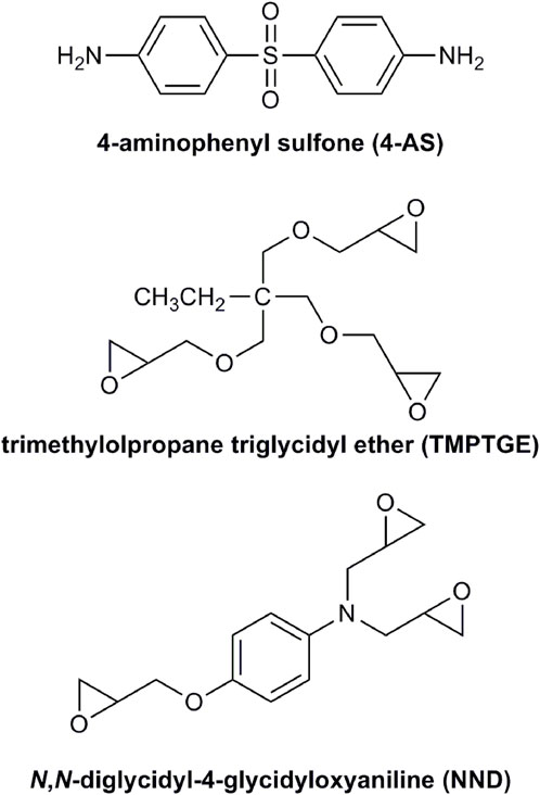
FIGURE 1. The amine curing agent (4-AS) and epoxy resins (TMPTGE, NND) used to prepare SMCs.
Neat epoxy samples were prepared with 4-AS at 97% purity from MilliporeSigma (St. Louis, MO) and the two epoxy resins. TMPTGE and NND were obtained as 100% purity liquid monomers from MilliporeSigma. Each epoxide was mixed with 4-AS at an amine to epoxide mole ratio of 0.75:1.00. This mole ratio was chosen to obtain a completely polymerized epoxy. Each of the primary amine groups on 4-AS reacted with two epoxide rings by nucleophilic addition. Therefore, only 0.75 mol equivalent of 4-AS was needed to entirely react with the three epoxide rings on each molecule of TMPTGE or NND.
In order to create net-shaped samples, molds were fabricated using 3D printed antimolds. The antimolds were printed from 1.75 mm polylactic acid (PLA) filament sold by Maker Gear (Beachwood, OH) using a Maker Gear M2 3D Printer and a CAD file created in SolidWorks (3DS, Waltham, MA). The mold was made from Pt-cured Smooth-Sil™ 960 silicone rubber (Smooth-On Inc., Macungie, PA). Parts A and B of the silicone rubber were mixed in a 100A:10B ratio, degassed in a vacuum chamber by cycling between vacuum and atmospheric pressure until no further bubbling occurred upon application of vacuum (∼10 min), and poured into the antimold to cure for 16 h at room temperature. The finished molds were released from the antimolds and inspected prior to use. The interior of the molds was coated with high-temperature silicone vacuum grease (Dow Corning, Midland, MI) to allow easy removal of the epoxy samples.
The 4-AS and epoxide were heated at 180°C for 10–12 min to melt and dissolve the 4-AS precursor while stirring with a spatula or stir bar (for neat samples). The homogeneous amine and epoxide mixture was then spread or poured into the greased mold and cured for 12 h at the chosen cure temperature. The final cure temperatures were chosen after differential scanning calorimetry (DSC) measurement of the glass transition temperature (Tg) of the neat epoxy. Before analysis by DSC, epoxy samples were initially cured at a temperature of 135°C or 180°C to harden the epoxy. However, the NND epoxide proved too reactive to begin the multi-hour cure at 180°C. If the amine and epoxide mixture was held at 180°C for much longer than 12 min, the mixture underwent thermal runaway. Therefore, once the 4-AS was dissolved, the hot plate temperature was reduced to 140°C and held there for an hour. It was then subsequently stepped up to 180°C by raising the temperature by 10°C every 10 min. It took about 30–60 s to reach the next 10°C increment. This temperature reduction slowed the cure kinetics enough to avoid thermal runaway. The final cure temperature was identified through DSC measurements as the temperature which maximized the measured Tg without decomposing the epoxy.
The glass transition temperatures of the neat 4-AS/TMPTGE and 4-AS/NND cured epoxies were measured on a Netzsch Polyma 214 Differential Scanning Calorimeter (DSC). Net-shaped, bulk samples (circular, 5 mm in diameter, 1–1.5 mm thick) were prepared that fitted the dimensions of the aluminum DSC pans. Samples were tested in sealed pans with their lids pierced to allow purging with air. Air was used as the purge gas at a flow rate of 80 mL/min to simulate the environment in which the epoxies would be cured and theoretically used. The epoxy samples were cycled 3–4 times in the DSC over temperatures ranging from 25°C to 300°C at a heating rate of 15°C/min. Glass transition temperatures were measured as endothermic inflection points. The onset of decomposition was measured for 4-AS/TMPTGE by thermogravimetric analysis (TGA), which showed a rapid decrease in sample mass at about 290°C (see Supplementary Figure S1). Therefore, the TMPTGE and NND epoxies were kept below this temperature while curing. The reappearance of the Tg endotherm over multiple DSC heating cycles confirmed that the epoxies were cured below the point of epoxy decomposition.
Epoxy-iron nitride composite samples were cured in the same manner as the neat epoxies described above. However, there were two sources of iron nitride used: commercially available iron nitride powder (Alfa Aesar, Tewksbury, MA, 325 mesh, FexN where x = 3–4) and the same commercially available iron nitride powder that had been annealed to produce nearly phase-pure Fe4N. In a representative experiment, ∼4 g of Fe3-4N was added to a ceramic crucible in a glove box under nitrogen. The crucible was placed in a Barnstead International Type 1,300 muffle furnace inside a glove box and heated to 542°C (see Results and Discussion), then held at that temperature for 40 min. The bulk sample was stored inside the glove box long-term.
Quantitative powder XRD (x-ray diffraction) confirmed that the annealing process produced ∼95% Fe4N (see Supplementary Material). Quantitative powder XRD analysis was performed using a Siemens θ−θ D500 XRD diffractometer using a sealed tube X-ray source (Cu Kα radiation), a graphite monochromator, and a scintillation detector. The sample was isolated within a special beryllium dome holder to prevent oxidation of the sample during analysis (Rodriguez, 2008). Typical scan parameters were 10°–80° 2θ, 0.02° step size and 15 s count time. Quantitative weight percent values for the final heat-treated product were determined via Rietveld refinement (whole pattern fitting) within the software Jade 8 (Material Data, Inc., Livermore, CA). High temperature XRD analysis was performed using a Scintag PAD X diffractometer equipped with a sealed tube X-ray source (Cu Kα radiation), a solid-state Ge detector and a Buhler high temperature stage (Pt/Rh). Acquisition was carried out under flowing He gas atmosphere to prevent oxidation and maintain an inert atmosphere. The sample was heated from room temperature to maximum temperatures ranging from 500°C–700°C in 10°C increments with a heating rate of 40°C/min between each scan. Typical scan parameters were 10°–65° 2θ, 0.04° step size and 1 s count time.
To prepare all SMCs, 4-AS powder was first ball-milled with iron nitride powder in an 8000M Spex Mixer Mill, using an 8004SS 55 mL steel-jacketed WC grinding vial for mill pot, one 7/16” WC ball for the mill ball, <40 g mill load, at a speed of 1,060 cycles/min at 60 Hz, 115V, for 18 min. The iron nitride theoretical vol% ranged from ∼26 up to 90%, depending on the vol% desired. A stoichiometric amount of milled powder was mixed thoroughly by spatula with the epoxy resin while heating to 180°C for 10–12 min to dissolve with melt the 4-AS. The mixture was then spread into a preheated mold and cured as described above. As the vol% of iron nitride increased, the mixture became thicker, more challenging to mix thoroughly and transfer consistently into molds.
For all 4-AS/NND SMCs with >65 vol% loading of iron nitride, samples were hot pressed to form high-density SMCs with maximized relative permeability. Milled 4-AS/iron nitride and NND were mixed and heated for 10–12 min at 180°C to dissolve with melt the 4-AS and subsequently transferred to a 400 series stainless steel preheated 3 mm anvil die (Pellet Press Die Sets, Traverse City, MI) for hot pressing. The die was spray-coated with BN (boron nitride aerosol lubricant, Zyp Coatings, Inc., Oak Ridge, TN) to aid removal of the cured sample from the die. Samples were pressed using an International Crystal Laboratories (Garfield, NJ) 20 Ton E-Z Press™, a benchtop hydraulic press. To ensure that the die components were at the same temperature while preheating, the die anvil was kept in a 180°C oven until used. The die block and base plate were heated to 180°C with a heating band (Duraband© Heaters, Tempco Electric Heater Co., Wood Dale, IL). Die temperature was controlled by a benchtop temperature controller (Omega Engineering Inc., Norwalk, CT, Model CSi32R) after calibrating for the temperature difference between the set temperature (180°C) and the measured temperature inside the die. After transferring the uncured 4-AS/iron nitride/NND mixture to the die block and adding the preheated die anvil, samples were pressed at 63 MPa for 12 h with the heating band set at 180°C. Curing samples at 255°C in air caused some discoloration (presumably due to iron oxidation), so subsequent hot-pressed samples were cured at 255°C for 8 h in a glove box under nitrogen.
To determine the experimental iron nitride volume percentage, the total density of each SMC was determined with a Mettler Toledo (Columbus, OH) MS304TS/00 analytical balance equipped with an Archimedes density kit. The balance calculated the density and volume of each sample using the following formulas:
In these equations, ρ is the sample density, A is the weight of the sample in air, B is the weight of the submerged sample, V is the sample volume, ρ0 is the density of the auxiliary liquid, ρL is the density of air (0.0012 g/cm3), and α is a balance correction factor of 0.99985 for the air buoyancy of the adjustment weights (Mettler Toledo, 2021). Each sample was weighed in air and then submerged to obtain its balance-calculated density and volume. SMC length and diameter were also manually measured using digital calipers, and the total volume of each SMC was estimated using the formula for the volume of a cylinder (πr2h) or a toroid (πr2*2πR), as appropriate. The density of each neat, cured epoxy resin system was determined in a similar experiment using the Archimedes balance. The volume of epoxy resin in the SMC was then estimated using the equation:
The volume of Fe3-4N could be determined using the equation:
Finally, the volume percent of Fe3-4N was calculated:
SEM imaging was done on an SEC SNE-4500M Plus Tabletop SEM (NanoImages, Pleasanton, CA). The SEM samples were ground flat and polished with silicon carbide (300, 600, and 1,200 grit) and diamond abrasive pads to 0.1 μm smoothness. Samples were fixed to a 15 mm sample mount and were secured to the mount with carbon tape. Powder samples were prepared in the same fashion with the excess powder blown off. The 15 mm mount permitted imaging of samples at a working distance as low as 1 mm. SEM images were collected at 15 kV accelerating voltage under secondary electron (SE) and backscattered electron (BSE) modes. Images were taken at 250-3500× magnification under high vacuum with a spot size of 10–23. After acquisition, the images were analyzed using the National Institutes of Health-developed tool ImageJ. The SE images showed the surface topography of samples, while the BSE images showed the compositional variation in terms of atomic mass. The SEM images included here are given for illustration of the sample microstructure.
For B-H Analyzer analysis of bulk magnetic behavior, SMCs were molded into 9 mm outer diameter toroids using the same procedures described above. Two 4-AS/NND SMCs were cured at 255°C for 8 h in a glove box under nitrogen and analyzed both before and after the curing process. All toroids were wound 10–12 times with 30 AWG Jonard Tools (Elmsford, NY) insulated wire. The toroids were then connected to an Iwatsu (Tokyo, Japan) SY-8218 B-H Analyzer for alternating current (AC) hysteresis characterization. Hysteresis loops were collected at sinusoidal frequencies of 0.01–1,000 kHz over a magnetic field range of −500 to 500 A/m. The B-H Analyzer recorded relative permeability (µr), max magnetic flux density (Bm), and core loss (Pc) at these frequency ranges, which were used to generate data plots for comparison of the toroids.
For resistivity measurements, a Jandel (Leighton Buzzard, United Kingdom) Multi-Height Micro Position 4-Point Probe was connected to a Jandel RM3000+ DC power supply and a Keithley (Tektronix, Beaverton, OR) 2000 multimeter for reading voltage and current. Interpolated resistance of the disk (9.56 mm diameter, 3.80 mm thickness) was obtained by plotting voltage vs. current. Resistivity was then calculated by multiplying resistance by SMC surface area, divided by SMC length. Corrections were made for sample thickness, lateral sample dimensions and placement of the probe points relative to the sample edges. Optimal results were obtained by using double-sided tape between the sample and the probe plate. Large radius of curvature tungsten probe tips were used to ensure the tip area broke through any surface oxide with sufficient pressure. Two-probe resistance measurements were necessary between the inner and outer probes to establish adequate contact resistance.
Magnetometry was performed on a 14 T DynaCool PPMS (Physical Property Measurement System, Quantum Design, San Diego, CA) with the VSM (vibrating sample magnetometry) option. A 5-quadrant field sweep starting at zero field to ±7 T (±5.5 × 10⁶ A/m) at a sweep rate of 10 mT/s (7.9 × 10³ A/m-s) with a peak amplitude of 2 mm at a frequency of 40 Hz averaging over 1s was used to measure samples at 293 K. Samples for VSM measurement were mounted with their long axis in a vertical orientation parallel to the applied field to minimize demagnetization affects. Polyimide tape was used to attach the samples to a quartz or brass paddle.
Once the 4-AS/TMPTGE and 4-AS/NND amine-epoxy systems were chosen, both systems were evaluated for their cure chemistry and suitability as insulating matrices for the SMCs. This was done by performing both differential scanning calorimetry and thermogravimetric analysis (Table 1). TGA studies revealed a temperature at which the mass quickly decreased for the 4-AS/TMPTGE epoxy system, suggesting decomposition (see Supplementary Figure S1). This value was used to design appropriate DSC temperature programs by serving as an upper temperature limit for experiments to determine the Tg.
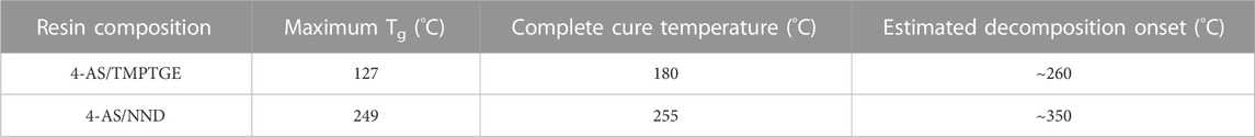
TABLE 1. DSC data for amine/epoxy resin systems used in the preparation of SMCs.
To check the upper cure temperature limit of the 4-AS/TMPTGE epoxy resin system, a sample that had been heated to 200°C for 30 min, then heated again at 135°C for 12 h, was subjected to the DSC program shown in Figure 2B. The sample was first heated to 180°C rapidly in the DSC and held at that temperature for 20 min, cooled to 90°C, rapidly heated to 300°C, cooled back to 90°C, and heated to 180°C. The sample showed a decomposition exotherm with an onset temperature of ∼260°C (Figure 2A). As further evidence that decomposition was occurring, a ∼14.4% mass loss was measured upon removing the sample from the DSC (see Supplementary Figure S6A). Therefore, to avoid any decomposition, the 4-AS/TMPTGE epoxy was subsequently cured at temperatures below 260°C.
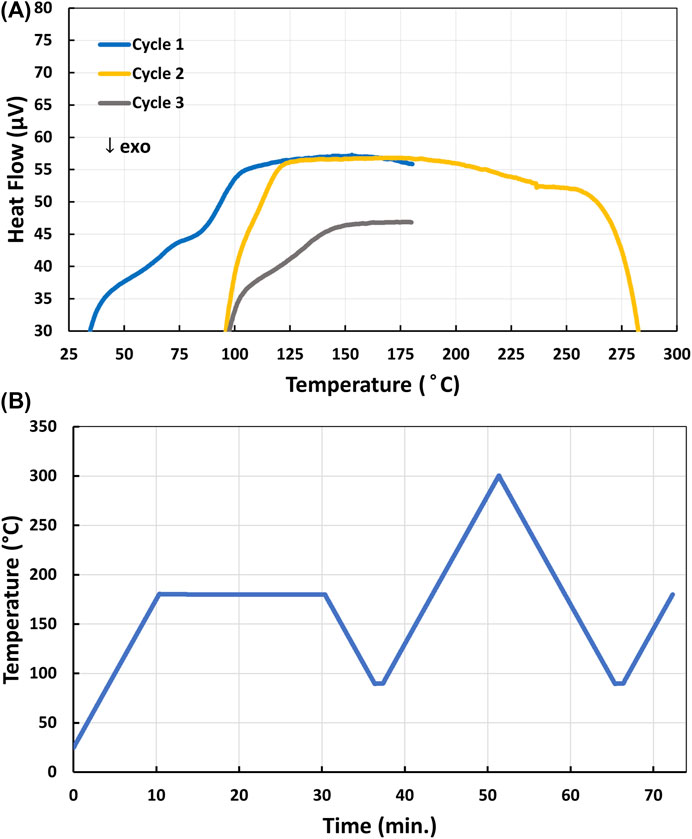
FIGURE 2. (A) DSC profile of the decomposition onset of 4-AS/TMPTGE epoxy cured at 135°C; (B) DSC program used to assess the decomposition onset of 4-AS/TMPTGE.
Initial curing trials showed that a sample of 4-AS/TMPTGE cured at 135°C for 12 h displayed exothermic phase transitions upon reaching ∼155°C, as well as shifts in Tg to higher T with each cycle (Figure 3A). Both observations suggested that the sample had not completely cured. This shift in Tg occurs because the polymer is continuing to cross-link and is a well-documented phenomenon (DiMarzio, 1964; Shibayama, 1975; Cook, 1978; Bellenger, 1987). As the network structure in the polymer becomes more rigid with cross-linking, the polymer must be heated to higher temperatures in order to relax the molecular structure and enter the rubbery stage associated with temperatures above the Tg. As further evidence of this, a 4-AS/TMPTGE sample cured for 12 h at 180°C was prepared and analyzed with an identical DSC program (25 °C
FIGURE 3. (A) DSC profile of the Tg endotherms of 4-AS/TMPTGE epoxy cured 12 h at 135°C suggesting incomplete cure; (B) DSC profile of the single Tg endotherm of 4-AS/TMPTGE epoxy cured 12 h at 180°C showing complete cure.
The upper cure temperature limit and Tg behavior of 4-AS/NND was similarly investigated by DSC. A 4-AS/NND sample which had been cured at 180°C for 12 h was cycled up to 345°C as shown in Figure 4. It was not possible to measure an initial Tg in heating cycle 1, as an exotherm centered at 250°C (corresponding to additional curing) interfered with the measurement. Only after the sample had gone through an additional heating cycle approaching 300°C, could the Tg of ∼250°C then be determined. However, any temperature exposures above 300°C induced thermal decomposition, which resulted in the lower Tg observed in heating cycle 3 for a “partially degraded” material. Further evidence of decomposition was found when upon removal from the DSC, the sample was reweighed and showed a mass loss of ∼4% (see Supplementary Figure S6B). To avoid decomposition, the 4-AS/NND epoxies were subsequently cured at temperatures below 300°C.
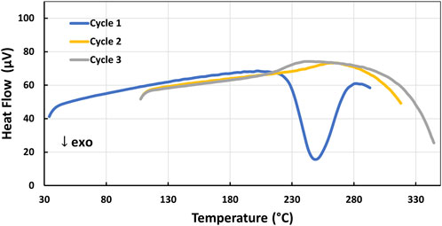
FIGURE 4. DSC profile of the decomposition exotherm onset (Cycles 2–3) of 4-AS/NND epoxy cured at 180°C.
After determining the upper cure temperature limit, further DSC experiments were conducted with the 4-AS/NND epoxy to identify the minimum cure temperature to obtain the maximum Tg. Prior to DSC analysis, a sample of 4-AS/NND was first heated to 200°C for 4 h. The minimum complete cure temperature was achieved by heating the sample to 255°C in the DSC, holding it there for an hour to cure the epoxy, and then cycling through heating and cooling cycles ranging from 150°C to 285°C as shown in Figure 5A and 5C. The endothermic Tg phase transition was observed at ∼249°C in the sample in cycles 2-4, and did not shift in temperature, confirming that the sample was fully cured at 255°C (Figure 5B).
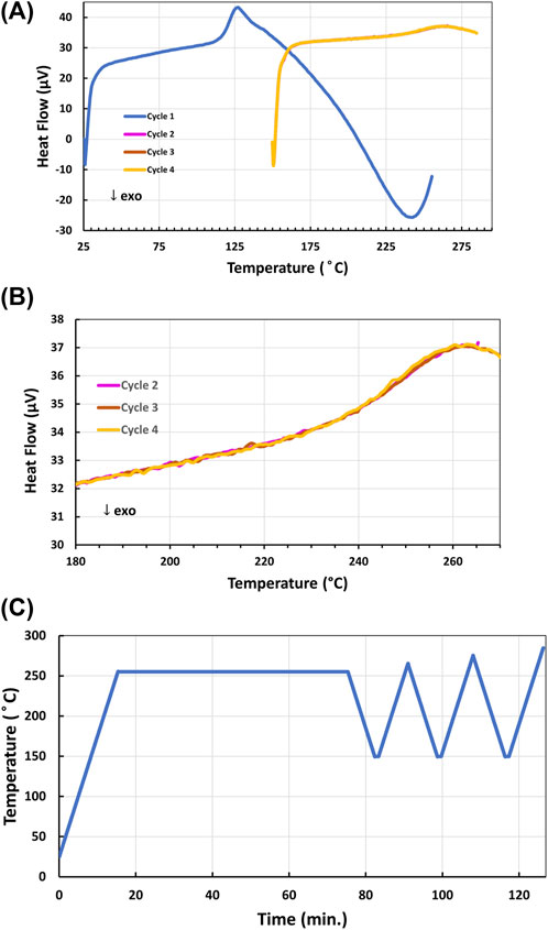
FIGURE 5. (A) DSC cycles 1–4 (with 2-4 overlapping) of the single Tg endotherm of 4-AS/NND epoxy resin after curing in the DSC at 255°C for 1 h during the first heating cycle; (B) DSC cycles 2-4 expanded from 180°C–285°C; (C) DSC program used to cure and analyze the Tg of 4-AS/NND.
As the 4-AS/NND epoxy system’s higher Tg of 249°C exceeded the minimum requirement of 150°C for electric motors and drives, attention turned to fabrication of SMCs from the 4-AS/NND epoxy system. However, curing at 255°C in air resulted in discoloration of the composite, presumably by oxidation of the iron. Therefore, the 4-AS/NND composites containing iron nitride were initially cured at 180°C for at least 4 h to harden the epoxy before completing a final high temperature cure on some samples under inert atmosphere at 255°C for 8–12 h.
Commercially available iron nitride was purchased as a mixture of Fe3N and Fe4N, but Fe4N has superior properties for incorporation into soft magnetic composites (Chen, 1991; Zhang, 2018). For ideal performance and consistency in magnetic properties, a method to make phase pure Fe4N was desired. Examination of the phase diagram of the iron nitride system suggested that it should be possible to reach the Fe4N phase at an elevated temperature (Wriedt, 1987; Coey, 1999). A straightforward heat treatment converted almost all of the Fe3N phase to Fe4N when conducted in an inert atmosphere (under nitrogen in a glove box). Temperature dependent X-ray diffraction data (XRD) of this process, collected under flowing nitrogen, is displayed in Figure 6. This data shows that at a temperature slightly above 550°C the diffraction peaks associated with the Fe3N disappear, leaving nearly phase pure Fe4N. Heating the sample either at too high of a temperature or for too long resulted in some conversion to elemental Fe, so the best approach was to heat the sample at 542°C for 40 min under nitrogen.
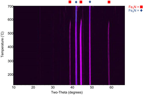
FIGURE 6. Temperature-dependent powder X-ray diffraction data demonstrating the conversion of Fe3-4N to mostly Fe4N above ∼550°C.
Quantitative powder XRD analysis showed that the powder was ∼95% Fe4N (see Supplementary Material). However, with the large amounts of iron nitride required to fabricate composites of workable size, only a few SMCs were made with ∼95% Fe4N in this work. Fe4N used outside of the glove box was generally air-stable, although it was stored in the glove box long-term. It was not left exposed to air long-term and analyzed for changes after exposure.
The milled amine and iron nitride mixture, as well as the cured composite, were examined by SEM to learn more about their morphology and composition. The milling time of 4-AS and iron nitride was varied to study effects on particle size and the final SMC, while the composition was varied to see how the microstructure of SMCs changed with loading of iron nitride in the composite (work in progress). SMC samples were prepared with iron nitride/4-AS milling times of 0–90 min and at compositions of 30, 40, 50, 65, and 77 theoretical vol% iron nitride in epoxy. The selected time for ball-milling Fe3-4N and 4-AS in this work was 18 min (see Supplementary Figures S2–S4).
A 65 vol% Fe3-4N in 4-AS/NND epoxy SMC was prepared as described in Materials and Methods. After polishing with silicon carbide and diamond abrasive pads down to 0.1 µm, the sample appeared shiny and metallic, as seen in Figure 7B, with the corresponding SEM images of the surface shown in Figures 7A and 7C. The SEM imaging shows the microstructure of the final composite. As can be seen in the SE image in Figure 7A, the Fe3-4N particles are packed together with gaps of roughly 1–5 μm. There are also visible macroscopic voids in the samples, which can be seen in the sample photo (Figure 7B). The micro and macroscopic voids result in samples which fall shy of the theoretical magnetic properties for these SMCs. The BSE image in Figure 7C, which reveals atomic mass distribution, shows that iron nitride particles are generally homogeneously dispersed throughout the epoxy matrix.
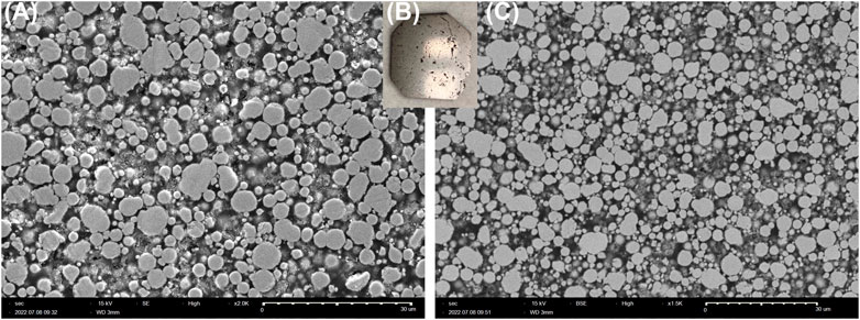
FIGURE 7. (A) Secondary Electron mode (SE) image, (B) sample photo, and (C) Backscattered Electron mode (BSE) image of a polished 65 vol% Fe3-4N SMC made with 4-AS/NND.
Figure 8 shows the microstructure of a ∼77 vol% Fe3-4N in NND/4-AS epoxy SMC which was prepared by hot pressing at 63 MPa for 12 h. The iron nitride particles are packed at much greater density, with spacing on the order of ≤1 μm. The high pressure applied in hot pressing enables the lower volume of epoxy to still bind the iron nitride powder into a solid composite. There is a certain volume percent of the sample that corresponds to voids, which helps explain the discrepancy between the theoretical Fe3-4N vol% of samples calculated from the precursors and the Fe3-4N vol% determined from experimental density.
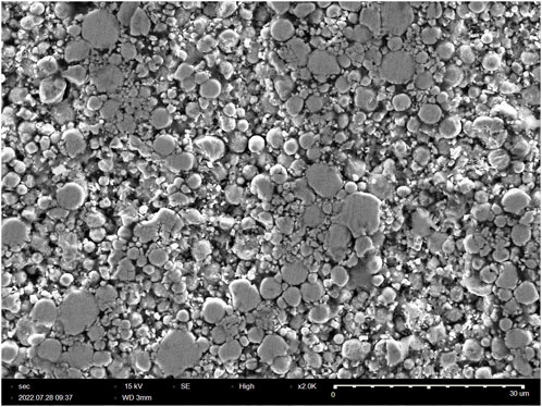
FIGURE 8. SEM image of ∼77 vol% Fe3-4N SMC made with 4-AS/NND using hot pressing at 63 MPa for 12 h.
Figure 9 and 10 show examples of some of the SMCs fabricated using both TMPTGE and NND. It was possible to cure SMCs into a variety of shapes, including toroids. As the vol% of iron nitride in the composites increased, they became thicker, more difficult to spread consistently into molds and to cure without surface defects, voids and bubbles. The cured epoxies also became increasingly brittle. Polishing and smoothing removed many of the surface defects on toroids so that they could be wound with wire for B-H analysis. To achieve over 65 vol% Fe3-4N, it was necessary to use hot pressing to maximize magnetic permeability. The epoxy component of the SMC, which insulates the iron nitride particles to prevent eddy currents, also creates a distributed air gap. Therefore, maximizing the saturation magnetization and the magnetic permeability of the SMC required maximizing the volume fraction of Fe3-4N filler. Hot pressing, in which the uncured sample is subjected simultaneously to high pressure and temperature, has proven successful in this (Mason, 1999). In fact, above 70% vol% Fe3-4N, the composite mixture would not cure into a solid shape without hot pressing. The highest vol% iron nitride reached thus far was ∼77% in the 4-AS/NND system (via hot pressing) and ∼65% in the 4-AS/TMPTGE system. No major differences were observed in the quality and appearance of SMCs made with the mixture of Fe3-4N versus those made with ∼95% Fe4N. Samples were usually black with lower vol% Fe3-4N. With higher volume loading, they appeared shiny and metallic when polished.
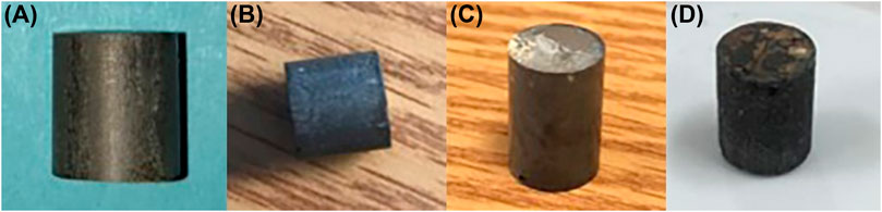
FIGURE 9. SMCs made from 4-AS/NND via hot pressing at 63 MPa for 12 h: (A) 71.4 vol% Fe3-4N; (B) 68.1 vol% Fe3-4N; (C) 61.3 vol% Fe3-4N; (D) 59.7 vol% Fe3-4N.
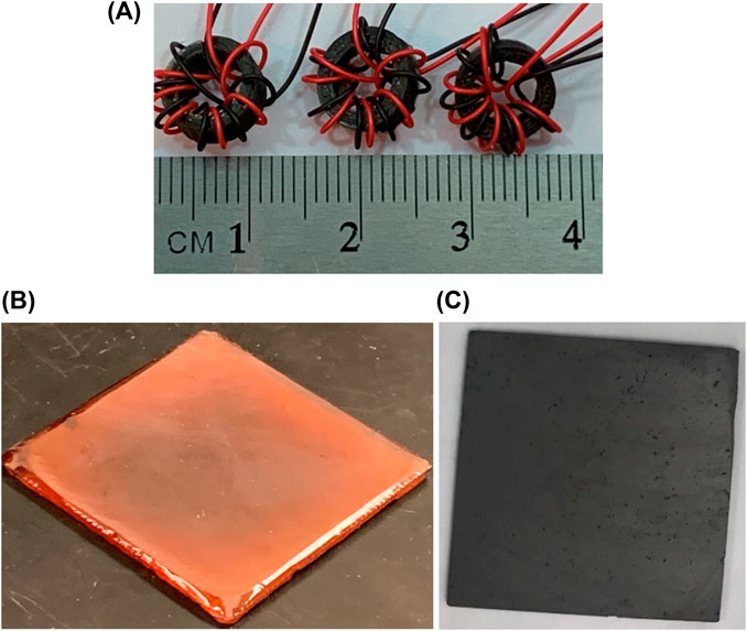
FIGURE 10. (A) 4-AS/TMPTGE/Fe3-4N toroids prepared for B-H Analyzer analysis; (B) bubble-free, cured and smoothed 4-AS/TMPTGE epoxy resin sample; (C) cured and smoothed 4-AS/TMPTGE epoxy composite with 65 vol% Fe3-4N.
SMCs were characterized with a B-H analyzer to determine their relative permeability. Consistent with expectations, as Fe3-4N volume loading increased, relative permeability increased, nearly exponentially (Figure 11A). This analysis could only be performed with SMCs that had successfully been fabricated into toroids, which was challenging at times due to decrease in workability as the Fe3-4N vol% increased and epoxy fraction decreased. Increasing the ratio of soft magnetic to non-magnetic phase is one way to increase permeability along with increasing compacting pressure. The non-magnetic phase tends to act as an air gap, decreasing permeability (Périgo, 2018). Future work will focus on fabricating toroids with increased volume loading via hot pressing and subsequently characterizing them with a B-H analyzer. For the same series of SMCs, relative permeability was found to be nearly independent of frequency up to 1 MHz (Figure 11B). Consistent with Figure 11A, the relative permeability increased as the vol% Fe3-4N increased.
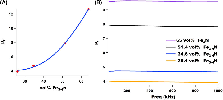
FIGURE 11. (A) Relative permeability (μr) of 4-AS/TMPTGE SMCs plotted as a function of vol% Fe3-4N. (B) Relative permeability (μr) of selected SMCs does not change significantly over several hundred kHz. Volume percent reported here is theoretical.
SMC samples were then characterized on a DynaCool PPMS with the vibrating sample magnetometry option. As expected, a higher saturation magnetic polarization was achieved with increasing vol% Fe3-4N, independent of epoxy resin choice. Hysteresis curves for composites made with TMPTGE can be found in the Supplementary Figure S5. Figure 12 shows the results for a series of SMCs prepared with increasing vol% Fe3-4N, using the 4-AS and NND epoxy system. Higher vol% Fe3-4N was only possible in this series through hot pressing. Future work will focus on achieving even higher volume loadings and Js values.
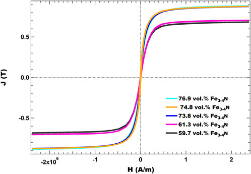
FIGURE 12. J(H) curves for various SMCs made with Fe3-4N. All were cured with 4-AS as the amine curing agent, NND as the epoxy resin and hot pressed at 63 MPa for 12 h.
To investigate the effect of curing a 4-AS/NND/62.4 vol% Fe3-4N toroid at 255°C for 8 h on its magnetic properties, the toroid was first prepared as described in Materials and Methods (heating at 180°C for 12 h). It was then characterized on the B-H analyzer to determine its relative permeability as a function of frequency. The sample then underwent a final cure under nitrogen in a glove box at 255°C for 8 h and was recharacterized on the B-H analyzer. As shown in Figure 13, there was only a slight change in the permeability of the sample, and it did not change with frequency. XRD analysis of the samples before and after the final curing showed no significant change in the composition of the Fe3-4N (see Supplementary Material).
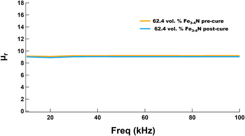
FIGURE 13. Relative permeability of a 62.4 vol% Fe3-4N/4-AS/NND toroid did not change significantly after a final cure at 255°C for 8 h under nitrogen.
Using the VMS option, the saturation magnetic polarization (Js), coercivity (Hc) and saturation magnetization (Ms) of SMCs were recorded (Table 2). Maximum Js values were about half of those found in Fe3-4N sheets (1.8 T) (Chen, 1991) and the value decreased as the calculated Fe3-4N vol% decreased. Not surprisingly, hot pressed samples with the maximum volume loading of Fe3-4N had the highest Js values. Values of Hc were about 4–5 times the target Hc of <1 kA/m, similar to those of tungsten, cobalt and chromium steel (Coey, 2010). However, these SMCs still qualify as soft magnets, given their Hc < 10 kA/m (Coey, 2010). Furthermore, decreases in Hc should be realized through improvements in volume loading, processing conditions, and post-processing. Future work will also focus on preparing SMCs with the ∼95% Fe4N to see if they are capable of higher Ms relative to those made with the commercially available, unannealed Fe3-4N mixture. Ms values generally correlated well with calculated Fe3-4N vol% values. Using a collinear four-point probe, the resistivity (ρ) of one SMC disk was measured at 1.9 × 10⁵ μΩ*m, comparable to the high resistivity NiZn and MnZn ferrites ('Nickel Zinc Ferrite Materials', 2023; 'Mn-Zn Ferrite Material characteristics', 2022). The preparation and testing of more SMC disks is an area of ongoing investigation.
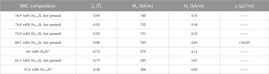
TABLE 2. Saturation magnetic polarization, saturation magnetization, coercivity, and resistivity of selected SMCs. * = Sample was prepared with TMPTGE epoxy resin and the volume percent reported is theoretical. Others were made with NND epoxy resin.
A new “bottom up” approach to making SMCs successfully produced a variety of cylinders, toroids, plates and disks, in which the soft magnetic material iron nitride was incorporated into an amine/epoxy resin. One amine cross-linking agent, 4-AS, was evaluated with two different epoxy resin systems, NND and TMPTGE. DSC studies confirmed that the 4-AS/TMPTGE system had a Tg of ∼127°C, and the 4-AS/NND system had a Tg of ∼249°C, well above the 150°C benchmark necessary for SMC application in electric motors and drives. In this approach, commercially available iron nitride obtained as a mixture of Fe3-4N was first ball-milled with the 4-AS to coat the particles evenly. A method for heat-treating the commercial iron nitride converted it to ∼95% Fe4N, provides a simple and straightforward source of nearly phase-pure soft magnetic material. While no evidence was yet found to suggest that a covalent bond formed between the iron nitride and the 4-AS, this is an area for further investigation as it would lead to a matrix-free composite and enable higher magnetic loading and a homogeneous structure. The powder mixture was combined with either NND or TMPTGE and heat-cured in a mold, providing a facile and flexible processing method. Reaching a volume percent loading of greater than 65% iron nitride required hot pressing at 63 MPa.
Magnetic characterization of several SMCs made with this process showed Js values of up to 0.9 T, about 2–4 times the Js (0.2–0.5 T) of soft ferrites (Coey, 2010) and roughly half that of silicon steel (∼2 T). Js values increased with increasing vol% iron nitride. All samples had Hc values less than 10 kA/m, confirming their classification as soft magnetic materials. Decreases in Hc can be realized through improvements in vol% loading, processing conditions, and post-processing. Samples had flat permeability out to 1 MHz, even after a second curing step at 255°C to reach Tg, making these materials ideal for use as inductor cores in high frequency power electronics. One sample possessed resistivity on the order of 105 μΩ*m, comparable with high resistivity ferrites. Future work will focus on further increasing the volume loading and processing parameters to achieve higher Js and µr and lower Hc so that these promising materials can be investigated for applications in axial flux electric motors, motor drives and high frequency power electronics.
The raw data supporting the conclusion of this article will be made available by the authors, without undue reservation.
MH: Writing–review and editing, Data curation, Formal Analysis, Investigation, Methodology, Supervision. GF: Writing–review and editing, Data curation, Investigation. CP: Data curation, Formal Analysis, Investigation, Supervision, Writing–review and editing. RD: Data curation, Formal Analysis, Software, Writing–review and editing. TS: Data curation, Formal Analysis, Investigation, Methodology, Supervision, Writing–review and editing. EJ: Data curation, Investigation, Writing–review and editing. TS: Data curation, Investigation, Writing–review and editing. NS: Data curation, Validation, Writing–review and editing. SF-W: Data curation, Investigation, Writing–review and editing. MR: Data curation, Formal Analysis, Resources, Writing–review and editing. LW: Writing–original draft, Writing–review and editing. TM: Conceptualization, Funding acquisition, Methodology, Project administration, Resources, Supervision, Writing–review and editing.
The author(s) declare financial support was received for the research, authorship, and/or publication of this article. This work was supported by the Electric Drivetrain Consortium managed by Susan Rogers of DOE’s Vehicle Technologies Office.
We thank Nichole R. Valdez for assistance analyzing XRD data. Sandia National Laboratories is a multimission laboratory managed and operated by National Technology & Engineering Solutions of Sandia, LLC, a wholly owned subsidiary of Honeywell International Inc., for the U.S. Department of Energy’s National Nuclear Security Administration under contract DE-NA0003525. This paper describes objective technical results and analysis. Any subjective views or opinions that might be expressed in the paper do not necessarily represent the views of the U.S. Department of Energy or the United States Government.
The authors declare that the research was conducted in the absence of any commercial or financial relationships that could be construed as a potential conflict of interest.
All claims expressed in this article are solely those of the authors and do not necessarily represent those of their affiliated organizations, or those of the publisher, the editors and the reviewers. Any product that may be evaluated in this article, or claim that may be made by its manufacturer, is not guaranteed or endorsed by the publisher.
The Supplementary Material for this article can be found online at: https://www.frontiersin.org/articles/10.3389/fmats.2023.1258382/full#supplementary-material
Bellenger, V., Verdu, J., and Morel, E. (1987). 'Effect of structure on glass transition temperature of amine crosslinked epoxies. J. Polym. Sci. Part B Polym. Phys. 25, 1219–1234. doi:10.1002/polb.1987.090250604
Bhattacharyya, S. (2015). 'Iron nitride family at reduced dimensions: A review of their synthesis protocols and structural and magnetic properties. J. Phys. Chem. C 119, 1601–1622. doi:10.1021/jp510606z
Chen, S. K., Jin, S., Tiefel, T. H., Hsieh, Y. F., Gyorgy, E. M., and Johnson, D. W. (1991). Magnetic properties and microstructure of Fe4N and (Fe,Ni)4N. J. Appl. Phys. 70, 6247–6249. doi:10.1063/1.350010
Coey, J. M. D., and Smith, P. A. I. (1999). 'Magnetic nitrides. J. Magnetism Magnetic Mater. 200, 405–424. doi:10.1016/s0304-8853(99)00429-1
Cook, W. D. (1978). 'An analysis of the effect of crosslinking on the Tg of polyester and other networks. Eur. Polym. J. 14, 715–720. doi:10.1016/0014-3057(78)90019-8
Dach, B. I., Rengifo, H. R., Turro, N. J., and Koberstein, J. T. (2010). 'Cross-Linked “matrix-free” nanocomposites from reactive polymer-silica hybrid nanoparticles. Macromolecules 43, 6549–6552. doi:10.1021/ma101054w
DiMarzio, E. A. (1964). 'On the second-order transition of a rubber. J. Res. Natl. Bureau Standards- A. Phys. Chem. 68A, 611–617. doi:10.6028/jres.068a.059
Electrical and Electronics Technical Team Roadmap, (2017). Electrical and electronics technical Team Roadmap. USA: US Drive. Available from: https://www.energy.gov/eere/vehicles/articles/us-drive-electrical-and-electronics-technical-team-roadmap.
'Electric Motor Products', (2015). Crosslink Technology Inc. Available from: http://www.crosslinktech.com/products-by-application/featured-electric-motor-products.html.
Guo, Y., Ba, X., Liu, L., Lu, H., Lei, G., Yin, W., et al. (2023). A review of electric motors with soft magnetic composite cores for electric drives. Energies 16, 2053. doi:10.3390/en16042053
Iron nitride certificate of analysis, Catalog No. 088198.22, (2022). Iron nitride certificate of analysis, Catalog No. 088198.22. Available from: https://www.thermofisher.com/document-connect/document-connect.html?url=https://assets.thermofisher.com/TFS-Assets%2FGC%2Fcertificate%2FCertificates-of-Analysis%2F88198-U19A019.pdf.
Jin, F-L., Li, X., and Park, S.-J. (2015). 'Synthesis and application of epoxy resins: A review. J. Industrial Eng. Chem. 29, 1–11. doi:10.1016/j.jiec.2015.03.026
Kollàr, P., Bircakova, Z., Füzer, J., Bures, R., and Faberova, M. (2013). 'Power loss separation in Fe-based composite materials. J. Magnetism Magnetic Mater. 327, 146–150. doi:10.1016/j.jmmm.2012.09.055
Lefebvre, L. P., Pelletier, S., and Gelinas, C. (1997). 'Effect of electrical resistivity on core losses in soft magnetic iron powder materials. J. Magnetism Magnetic Mater. 176, L93–L96. doi:10.1016/s0304-8853(97)01006-8
Li, W., Su, G., Li, W., Ying, Y., Yu, J., Zheng, J., et al. (2022). 'Monomolecular cross-linked highly dense cubic FeCo nanocomposite for high-frequency application. J. Mater. Sci. 57, 13481–13495. doi:10.1007/s10853-022-07487-z
Mason, P., Atallah, K., and Howe, D. (1999). “Hard and soft magnetic composites in high speed flywheels,” in ICCM-12 International Committee on Composite Materials Conference, Paris, July 5th-9th, 1999.
Mettler Toledo, Inc, (2021). Reference manual, density kit for advanced and standard analytical balances. Available from: www.mt.com/Density-Kit-advanced-RM.
Mn-Zn Ferrite Material characteristics, (2022). Mn-Zn ferrite material characteristics. Tokyo, Japan: TDK Corporation. Available from: https://product.tdk.com/system/files/dam/doc/product/ferrite/ferrite/ferrite-core/catalog/ferrite_mn-zn_material_characteristics_en.pdf.
Mochalin, V., Neitzel, I., Etzold, B. J. M., Peterson, A., Palmese, G., and Gogotsi, Y. (2011). 'Covalent incorporation of aminated nanodiamond into an epoxy polymer network. ACS Nano 5, 7494–7502. doi:10.1021/nn2024539
New structural adhesive from Delo for magnet bonding has high temperature stability, (2019). “New structural adhesive from Delo for magnet bonding has high temperature stability,” in Magnetics business and Technology. Available from: https://magneticsmag.com/new-structural-adhesive-from-delo-for-magnet-bonding-has-high-temperature-stability/.
Nickel Zinc Ferrite Materials, (2023). Nickel zinc ferrite materials. Bethlehem, Pennsylvania: National Magnetics Group, Inc. Available from: https://www.magneticsgroup.com/material/nickel-zinc-ferrite/.
Périgo, A., Weidenfeller, B., Kollàr, P., and Füzer, J. (2018). 'Past, present, and future of soft magnetic composites. Appl. Phys. Rev. 5, 031301. doi:10.1063/1.5027045
Poškovic, E., Franchini, F., Ferraris, L., Fracchia, E., Bidulska, J., Carosio, F., et al. (2021). Recent advances in multi-functional coatings for soft magnetic composites. Materials 14, 6844. doi:10.3390/ma14226844
Rodriguez, M. A., Boyle, T. J., Pin, Y., and Harris, D. L. (2008). A beryllium dome specimen holder for XRD analysis of air sensitive materials. Powder Diffr. 23, 121–124. doi:10.1154/1.2912452
Rodriguez-Sotelo, D., Rodriguez-Licea, M. A., Soriano-Sanchez, A. G., Espinosa-Calderon, A., and Perez-Pinal, F. J. (2020). Advanced ferromagnetic materials in power electronic converters: A state of the art. IEEE Access 8, 56238–56252. doi:10.1109/access.2020.2982161
Schoppa, A., and Delarbre, P. (2014). 'Soft magnetic powder composites and potential applications in modern electric machines and devices. IEEE Trans. Magnetics 50, 1–4. doi:10.1109/tmag.2013.2290135
Shibayama, K. (1975). 'Temperature dependence of the physical properties of crosslinked polymers. Prog. Org. Coatings 3, 245–260. doi:10.1016/0300-9440(75)80009-9
Shokrollahi, H., and Janghorban, K. (2007). Soft magnetic composite materials (SMCs). J. Mater. Process. Technol. 189, 1–12. doi:10.1016/j.jmatprotec.2007.02.034
Silveyra, J. M., Ferrara, E., Huber, D. L., and Monson, T. C. (2018). 'Soft magnetic materials for a sustainable and electrified world. Science 362, eaao0195. doi:10.1126/science.aao0195
Sugawa, Y., Ishidate, K., Sonehara, M., and Sato, T. (2013). 'Carbonyl-Iron/Epoxy composite magnetic core for planar power inductor used in package-level power grid. IEEE Trans. Magnetics 49, 4172–4175. doi:10.1109/tmag.2013.2250925
Super CoreTM Electrical steel sheets for high-frequency application, (2017). Super CoreTM Electrical steel sheets for high-frequency application. Tokyo: JFE Steel Corporation. Available from: http://www.jfe-steel.co.jp/en/products/electrical/catalog/f1e-002.pdf.
Taghvaei, A. H., Shokrollahi, H., and Janghorbana, K. (2009). 'Properties of iron-based soft magnetic composite with iron phosphate–silane insulation coating. J. Alloys Compd. 481, 681–686. doi:10.1016/j.jallcom.2009.03.074
Watt, J., Bleier, G. C., Romero, Z. W., Hance, B. G., Bierner, J. A., Monson, T. C., et al. (2018). Gram scale synthesis of Fe/FexOycore–shell nanoparticles and their incorporation into matrix-free superparamagnetic nanocomposites. J. Mater. Res. 33, 2156–2167. doi:10.1557/jmr.2018.139
Wei, X., Jin, M.-L., Yang, H., Wang, X.-X., Long, Y.-Z., and Chen, Z. (2022). Advances in 3D printing of magnetic materials: fabrication, properties, and their applications. J. Adv. Ceram. 11, 665–701. doi:10.1007/s40145-022-0567-5
Wriedt, H. A., Gokcen, N. A., and Nafziger, R. H. (1987). 'The Fe-N (Iron-Nitrogen) system. Bull. Alloy Phase Diagrams 8, 355–377. doi:10.1007/bf02869273
Yan, Y., Moss, J., Ngo, K. D. T., Mei, Y., and Lu, G.-Q. (2017). 'Additive manufacturing of toroid inductor for power electronics applications. IEEE Trans. Industry Appl. 53, 5709–5714. doi:10.1109/tia.2017.2729504
Yun, H., Kim, J., Paik, T., Meng, L., Sung Jo, P., Kikkawa, J. M., et al. (2016). 'Alternate current magnetic property characterization of nonstoichiometric zinc ferrite nanocrystals for inductor fabrication via a solution based process. J. Appl. Phys. 119, 113901. doi:10.1063/1.4942865
Zhang, C., Li, X., Jiang, L., Tang, D., Xu, H., Zhao, P., et al. (2021). '3D printing of functional magnetic materials: from design to applications. Adv. Funct. Mater. 31, 2102777. doi:10.1002/adfm.202102777
Zhang, C., Liu, X., Li, M., Liu, C., Li, H., Meng, X., et al. (2018). 'Preparation and soft magnetic properties of gamma'-Fe4N particles. J. Mater. Sci. Mater. Electron. 29, 1254–1257. doi:10.1007/s10854-017-8029-5
Keywords: soft magnetic composite (SMC), iron nitride, epoxy resin, magnetometry, net-shaped, hot pressing, toroid
Citation: Hoyt MR, Falcon GI, Pearce CJ, Delaney RE, Stevens TE, Johnson EM, Szenderski TM, Sorenson NR, Fultz-Waters SF, Rodriguez MA, Whalen LJ and Monson TC (2023) Fabrication and characterization of net-shaped iron nitride-amine-epoxy soft magnetic composites. Front. Mater. 10:1258382. doi: 10.3389/fmats.2023.1258382
Received: 13 July 2023; Accepted: 12 September 2023;
Published: 06 October 2023.
Edited by:
Harshida Parmar, Ames National Laboratory, United StatesReviewed by:
Guanglei Wu, Qingdao University, ChinaCopyright © 2023 Hoyt, Falcon, Pearce, Delaney, Stevens, Johnson, Szenderski, Sorenson, Fultz-Waters, Rodriguez, Whalen and Monson. This is an open-access article distributed under the terms of the Creative Commons Attribution License (CC BY). The use, distribution or reproduction in other forums is permitted, provided the original author(s) and the copyright owner(s) are credited and that the original publication in this journal is cited, in accordance with accepted academic practice. No use, distribution or reproduction is permitted which does not comply with these terms.
*Correspondence: Todd C. Monson, dG1vbnNvbkBzYW5kaWEuZ292
Disclaimer: All claims expressed in this article are solely those of the authors and do not necessarily represent those of their affiliated organizations, or those of the publisher, the editors and the reviewers. Any product that may be evaluated in this article or claim that may be made by its manufacturer is not guaranteed or endorsed by the publisher.
Research integrity at Frontiers
Learn more about the work of our research integrity team to safeguard the quality of each article we publish.