 Cheng Cheng1
 Chaohui Wang
95% of researchers rate our articles as excellent or good
Learn more about the work of our research integrity team to safeguard the quality of each article we publish.
Find out more
ORIGINAL RESEARCH article
Front. Mater. , 01 September 2023
Sec. Structural Materials
Volume 10 - 2023 | https://doi.org/10.3389/fmats.2023.1245955
A deep exploration was conducted on the evolution law of the mechanical properties of salt rock fillers under the influence of different forming parameters in the Lop Nor area to promote the engineering application process of salt rock. The accuracy of primary regression, square regression, and support vector machine (SVM) regression algorithms in predicting the mechanical properties of salt rock fillers was compared, and the most accurate prediction model for the California bearing ratio (CBR) and rebound modulus of salt rock fillers were recommended. The results showed that the optimal brine content of SC-40, SC-20, and SC-10 salt rock fillers was between 8.2% and 9.3%, with a dry density of approximately 1.69–1.76 g/cm3. The CBR of salt rock samples gradually decreased with an increase in brine content, and the rebound modulus was higher than 90.6 MPa. As the compaction degree increased, the CBR value increased significantly, and the rebound modulus increased by approximately 28.1 MPa. As the immersion time increased, the mechanical properties of salt rock gradually decreased. Among the various regression models, the SVM prediction model had the highest accuracy index coefficient of determination (R2), whereas the mean absolute percentage error (MAPE), root mean square error (RMSE), and mean absolute error (MAE) were the smallest. Therefore, the SVM prediction model was recommended to accurately estimate the mechanical properties of salt rock roadbed fillers and provide a reference for the regulation of compaction parameters and the guarantee of bearing capacity characteristics of salt rock roadbeds.
Strengthening resource conservation and intensive utilization and improving the level of resource recycling have become important development directions for modern highway construction in the western region. There is a shortage of traditional construction materials, such as water, soil, and sand, in the Lop Nor area of eastern Xinjiang (Li et al., 2021). At the same time, salt rocks of high crystallinity are widely distributed, with strong bonding ability and good self-healing performance. Salt crystals fill the pores of the soil with a relatively high bearing capacity (Song et al., 2018). Salt rock is gradually used in roadbed filling engineering of local roads and railways. However, the geological conditions in the Lop Nor area are extremely complex, the natural environment is very harsh, and the existing salt rock road construction technology has not formed a complete system yet, making the evolution characteristics of the mechanical properties of salt rock engineering more definite, which has great significance for the rational utilization of salt rock resources and scientific guidance for the construction upgrading of roads with salt rock subgrade.
Since the 1970s, researchers have conducted a series of studies on the various engineering properties of salt rock materials. Moazenian and Abedi (2021) clarified the influence of different salt rock shapes on the mechanical parameters, including uniaxial compressive strength, deformation modulus, Poisson’s ratio, and internal friction angle. Li et al. (2023) conducted several triaxial creep–fatigue mechanics tests on salt rock and examined creep–fatigue damage under various confining pressures. Li et al. (2021) conducted triaxial fatigue tests on salt rocks from Pakistan and explored the influence of different confining pressures and stress levels on the interval fatigue of salt rocks under triaxial conditions. In addition, Fan et al. (2019) used discontinuous cyclic loading tests to evaluate the fatigue performance of salt rock, and the results showed that the fatigue life of the sample was significantly reduced under discontinuous cyclic compression. Cheng et al. (2021) predicted the true creep rate of the salt cavern based on the test results of the creep rate and proposed a new nonlinear creep damage constitutive model. Wang et al. (2020) proposed a new creep damage constitutive model for rock using the continuous damage mechanics theory. When using salt rock for infrastructure filling projects of roads and railways, the unique engineering characteristics of salt rock have gradually led to the formation of diseases such as water immersion, dissolution, subsidence, and slope collapse in construction projects. Gao et al. (2015) combined the precipitation and engineering activity characteristics of the Qinghai–Tibet Railway region to investigate the factors affecting the stability of the roadbed and studied the salt solution disease of salt lake roadbed under the influence of brine. Moreover, Wang et al. (2023)studied the law of salt expansion of salt rock fillers using the multiple freeze–thaw cycle and comprehensively evaluated the deformation characteristics of the salt rock subgrade in Yanhu District. Xi et al. (2022) optimized the construction process of the salt rock subgrade and comprehensively evaluated the post-construction temperature change and deformation characteristics of the salt rock subgrade. However, research on the mechanical properties of salt rock fillers for subgrade was relatively weak, and the characteristics of changes in salt rock mechanical properties under different influencing factors need further clarification.
Due to the coupling effect of multiple factors, such as brine content, particle bonding compactness, and immersion time, on the strength of salt rock roadbeds during road construction (Zhang et al., 2019), the quantitative relationship between these factors was unclear. Therefore, it was particularly necessary to consider the impact of various factors on the mechanical properties of salt rock roadbeds and achieve quantitative performance estimation. Regression analysis methods were commonly used in statistics to determine the quantitative relationship between two or more variables and the strength of the influence of multiple independent variables on a dependent variable (Xu, 2017). This method used nonlinear log transformation and did not require a linear relationship between the independent and dependent variables. Through multiple iterations and accuracy tests, the prediction results could achieve high estimation accuracy (Lv et al., 2020). During the road construction process, factors such as the brine content, compaction degree, and immersion time of salt rock fillers are closely related to the mechanical properties of the road, and the degree of influence presents a nonlinear state. Therefore, nonlinear regression analysis methods can be attempted to estimate performance.
Accordingly, this study conducted an experimental analysis of the influencing factors of applied mechanics characteristics, such as compaction characteristics, California bearing ratio (CBR), and rebound modulus of salt rock fillers in the Lop Nor area. The influence of brine content, compaction degree, and immersion time on the engineering characteristics of road salt rock fillers was comprehensively analyzed. Various analysis methods were used to build several classes of nonlinear regression models of CBR and rebound modulus. The best forecast model was optimized, and a quantitative relationship between the influencing factors was established, which can provide a technical reference for the construction process control of the salt rock subgrade.
Salt rock samples from the central area of Lop Nor Lake were used as test materials to study the engineering characteristics of salt rock materials in a targeted manner. By referring to the Test Methods of Soils for Highway Engineering (JTG 3430-2020), the soluble salt content of salt rock was determined using the mass method. The results of approximately 42%–65% are shown in Table 1, indicating that salt rock has a high soluble salt content. According to the specific steps of the Uniaxial Compressive Strength and Compressive Strength Test (T0221-2005) in the Test Methods of Rock for Highway Engineering (JTG E41-2005), the uniaxial compressive strength of the collected research object—salt rock—was measured to be approximately 5–15 MPa. Due to the rule in the Specifications for Design of Highway Subgrades (JTG D30-2015) that the uniaxial compressive strength < 20 MPa is called soft rock, the salt rock studied in this article belongs to the soft rock category.
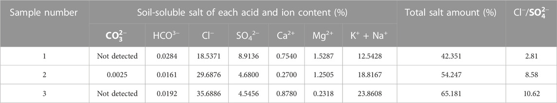
TABLE 1. Main soluble salt composition of salt rocks.
The maximum particle size of the roadbed filler is generally controlled within 100 mm according to the requirements of the Specifications for Design of Highway Subgrades (JTG D30-2015). For the convenience of experimental research, the Taibo theory (Wang et al., 2022) was used to design the prototype grading of the roadbed filler with a maximum particle size of 100 mm according to the following formula, and a similar grading method was adopted for grading reduction to facilitate the indoor test:
where P is the percent passage of particles on the sieve size d, %; D is the maximum particle size of filler, mm; d is the sieve size of particles, mm; and n is the grading index.
Huang et al. (2019) indicated that the coarse filler had good compactness when the n-value was set at 0.3–0.7. An n-value of 0.35 was selected, the similarity grading method was used, and the test prototype grading was scaled down according to three max particle size salt rock fillers (40, 20, and 10 mm). Then, they were numbered SC-40, SC-20, and SC-10 in sequence. The experimental prototype grading and three types of scale grading are shown in Figure 1.
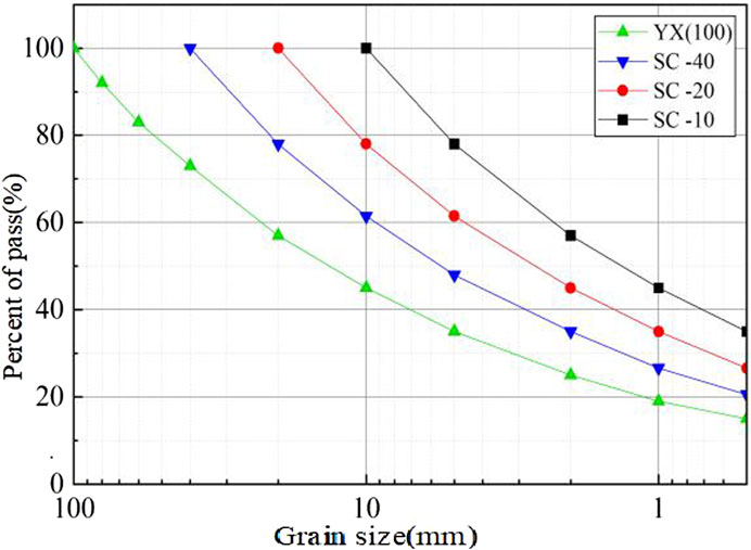
FIGURE 1. Particle grading curve of salt rock filler after similar grading scale.
The difference from traditional roadbed fillers is that salt rock has a higher soluble salt content. Salt rock fillers are generally mixed with saturated brine to avoid the dissolution of easily soluble salts by low-salinity brine and fresh water. Therefore, the brine content is a key influencing factor in controlling the compaction characteristics and even the engineering properties of the filler. The brine content can be determined using the oven-drying method in the Standard for Geotechnical Testing Method (GB/T 50123-2019). In addition, the compaction degree of roadbed soil directly affects the porosity of the soil. The greater the compaction degree, the smaller the porosity, the closer the particle arrangement, and, accordingly, the greater the strength of the soil structure. Therefore, it is necessary to systematically study the mechanical properties of salt rock roadbed fillers under different compaction degrees. At the same time, by considering that salt rock roadbed is inevitably immersed in underground low-salinity brine and ground precipitation, the strength rapidly decreases after immersion, which can lead to particle dissolution, softening deformation, and other uneven settlement deformation of the roadbed, thereby affecting the mechanical strength and stability of the roadbed. Therefore, it is necessary to study the wetting deformation characteristics and mechanical performance attenuation law of road salt rock fillers under the influence of the immersion time. Based on the aforementioned reasons, the brine content, compaction degree, and immersion time were selected as the main influencing factors on the mechanical properties of salt rock fillers for road use, and the effects of different molding parameters on the mechanical properties of salt rock were determined.
Analyzing the changes in the dry density of salt rock under different maximum particle sizes and recommending compaction parameters for salt rock roadbeds are important prerequisites for accurately grasping the engineering characteristics of salt rock fillers in roads. Before conducting the heavy compaction test, the undisturbed salt rock was crushed using a jaw crusher with a particle size of less than 40 mm. Subsequently, the crushed particles were dried and screened into seven different particle size zones of 40–20, 20–10, 10–5, 5–2, 2–1, 1–0.5, and less than 0.5 mm, as shown in Figure 2.
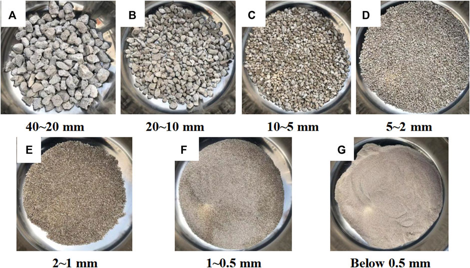
FIGURE 2. Frand screening of salt rock filler.
The screened salt rock fillers were mixed according to the upper section, the mixing rate of multiple brines was used for mixing, and the mixing time was not less than 24 h. Subsequently, a heavy compaction test was conducted, and the compaction process was performed according to the heavy compaction method in Specifications for Design of Highway Subgrades (JTG D30-2015).
Grading adopted a type of SC-20, and the sample was prepared according to the molding parameters shown in Table 2. The static pressure method was used to conduct the CBR test after forming the sample. For non-immersed samples, the samples with the plastic film were wrapped directly and allowed to stand for 24 h before conducting CBR tests. For the immersed sample, the surface filter paper was replaced after forming the sample, a porous plate was placed above the sample, and four load plates were placed above it. Subsequently, a dial gauge was installed to make contact with the top of the adjusting rod to test the deformation of the salt rock sample during the soaking process. After the dial gauge was installed, immersing it in brine for 4 days, the sample was taken out, and water stored on the top surface of the stand was removed. Then, the sample was left to stand and drain for 15 min for the CBR penetration test. The experiment used a universal material testing machine with a penetration loading speed of 1 mm/min. During the experiment, the penetration amount and penetration pressure values were automatically recorded by the systems, as shown in Figures 3A–D. Subsequently, the CBR values at 2.5 and 5 mm were calculated according to Formulas 2, 3, and the larger value of the two as the final CBR test result of the sample was selected:
where CBR is the California bearing ratio and p is the unit pressure, kPa.
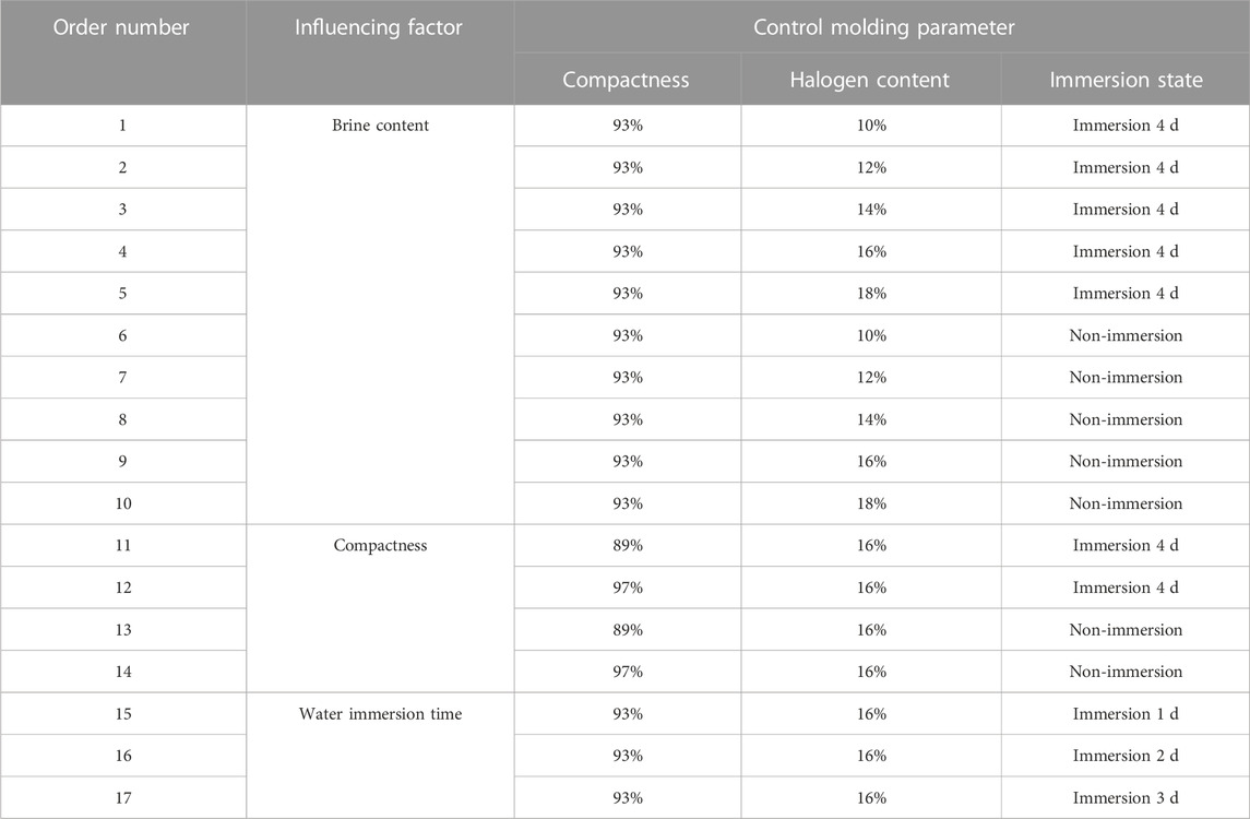
TABLE 2. Control molding parameters under different influencing factors.
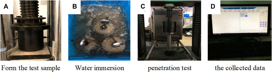
FIGURE 3. CBR test process of salt rock filler.
The forming control parameters of the samples used for the rebound modulus test are also shown in Table 2. The sampling method was the static pressure method, and the rebound modulus test was performed after sampling. The testing process was performed according to the Test Methods of Soils for Highway Engineering (JTG 3430-2020). First, the molded specimen was installed. After installation, the universal material testing machine applied a unit pressure of approximately 500 kPa to the top surface of the specimen. The preloading time was 1 min. During the preloading process, the instrument and the specimen should be well contacted, and then they should be unloaded and maintained for 1 min. During the rebound modulus testing process, the salt rock sample was subjected to five loading levels, with each level increasing by 100 kPa. When a single load was applied to the set load value, it continued to stabilize for 1 min. After stabilization was completed, it was unloaded for 1 min. After the entire process was completed, rebound deformation, L, under each loading level was calculated, and the rebound modulus was further calculated according to Formula (5). The experimental process is shown in Figure 4.
where E is the rebound modulus, p is the unit pressure, D is the bearing plate diameter, L is the test piece rebound deformation, and μ is Poisson’s ratio.
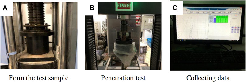
FIGURE 4. The rebound modulus test process.
Salt rock samples with a compaction degree of 93% were prepared using a brine content of 16%. The samples were immersed in brine for 1, 2, 3, and 4 days, respectively. After soaking for the specified time, the samples were taken out of the water tank and drained until no free water was discharged. The rebound modulus and CBR were tested separately, and the performance testing methods were the same as those in Sections 2.3.2 and 2.3.3. During the wetting process of salt rock samples, the deformation of each sample was observed during immersion, and a percentage meter was used to observe the deformation amount. After immersion, the bearing plate method was used to test the rebound deformation curves before and after graded loading and unloading during the test process to study the wetting deformation characteristics of salt rock roadbeds under different immersion times.
The regression analysis method, as a predictive modeling technique, can be used to predict the relationship between the dependent variable (estimated target) and the independent variable (parameters). Common types include linear, logical, polynomial, and stepwise regression (Zhao et al., 2021; Kang et al., 2022). Influencing factors such as brine content, compaction degree, and immersion time of salt rock samples are not correlated with each other. However, different factors can affect the mechanical properties of salt rock fillers. Therefore, the primary, square, and SVM regression methods that satisfy the independent variables and are not correlated with each other are selected as the forecast models.
To effectively evaluate the correlation between the various influencing factors of the mechanical properties of salt rock fillers and the CBR, the primary regression model expression for the engineering mechanical indicators of salt rock fillers constructed by factors such as brine content, compaction degree, and immersion time is presented as follows:
where Y1 is the brine content, Y2 is the compaction degree, Y3 is the immersion time, and Z is the engineering mechanics index.
The square regression model expression based on the brine content, compaction degree, and immersion time is presented as follows:
where Y1 is the brine content, Y2 is the compaction degree, Y3 is the immersion time, and Z is the engineering mechanics index.
Support vector machine (SVM), first proposed by Vapnik, is a machine learning algorithm based on statistical learning theory. It is commonly used for pattern classification and nonlinear regression. When dealing with nonlinear regression situations, the method used is to employ mapping functions to solve low-dimensional problems in high-dimensional space. The mapping function obtained from SVMs in high-dimensional space can be rewritten as in Formula (8). Formulas (9) and (10) show two typical mapping functions, the linear kernel function and the Gaussian kernel function (RBF), respectively. The SVM algorithm can accurately classify when the sample size is small and has good generalization ability. It is more suitable for small sample environments of salt rock filling engineering characteristic test results (Li et al., 2023):
where yi is the independent variable,
The algorithm structure selected an SVM model with a 3-3-1 single hidden layer, the transfer function of the output layer selected a nonlinear function, and the software was used to realize the forecast process. Before training the SVM, it is necessary to normalize and transpose all samples from the selected input and output layers. Multiple sets of sample data from the experiment were used to determine 10 sets as the training set and the remaining seven sets as the testing set using a disordered array model, completing the dataset partitioning process. According to the normalization criteria, all data in the training and testing sets were regressed to a range of 0–1, and the input and output data were transposed to make the behavior samples and columns in the dataset feature, meeting the matrix form requirements of the SVM model (Pedro et al., 2021). Figure 5 shows that the nonlinear SVM calculation process was divided into three steps: input, mapping, and output layers. Therefore, a forecast model was established with brine content, compaction degree, and immersion time as input terms, Gaussian kernel function as the mapping function, and road mechanical indicators as output terms.
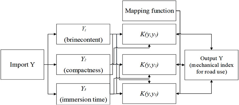
FIGURE 5. Structure diagram of SVM algorithm for engineering characteristics of salt rock filler.
The compaction curve is shown in Figure 6. The compaction curves of salt rock fillers under different brine contents obtained through quadratic polynomial fitting could exhibit significant single peaks, as shown in Figure 4. With an increase in water content, the dry density first increased and then decreased. The optimal brine content of different graded salt rock fillers was between 8.2% and 9.3%, with SC-10 having the highest brine content of 9.3% and SC-40 having the lowest brine content of approximately 8.2%. The trend of dry density was the opposite, with the maximum dry density of SC-40 grading reaching 1.76 g/cm3, followed by 1.71 g/cm3 of SC-20 grading, and the lowest maximum dry density of SC-10 grading, only 1.69 g/cm3. In addition, the dry density of SC-40 salt rock fillers changed significantly with water content, whereas the changes in SC-20 and SC-10 were relatively low. Notably, an appropriate increase in the content of fine particles in salt rock was beneficial for the filling material to absorb water and mix evenly, and the fine particles could fill the pores of coarse particles, making the sample compact and the construction compaction quality easier to control.
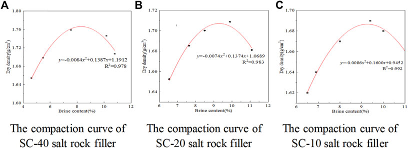
FIGURE 6. Compaction curve of salt rock filling under different brine content.
The penetration and pressure curves under different immersion states are shown in Figure 7. Figure 7A shows that the growth slope of the stress penetration curve of salt rock samples with different brine contents first increased and then decreased as the penetration depth increased without immersion. When the penetration was 2.5 mm, the stress level of the salt rock sample with 10% brine content increased to a maximum, whereas the brine content was 18%, which was the lowest. As penetration increased to 5 mm, the overall growth trend of stress values with different brine contents remained the same. When the brine content was low, the stress growth of the salt rock under load increased, indicating that the surface strength of coarse particles decreased under brine infiltration. However, an increase in brine content reduced the interparticle compression strength and improved lubrication. In particular, as the brine content increased, the resistance to external force deformation of the sample decreased. By analyzing Figure 7B, compared to the non-immersed conditions, the stress level of salt rock samples under different brine contents was generally lower, showing a decreasing trend as the brine content increased. When the brine content is 10%, the stress level of the salt rock sample was the highest, with unit pressures of 4,607 and 11,039.5 kPa at 2.5 and 5 mm, respectively. However, when the brine content was 18%, the stress level was the lowest, mainly due to differences in the initial dry density of the sample under different brine contents.
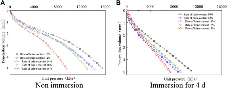
FIGURE 7. The penetration and stress relationship curve.
Based on the penetration and stress relationship curves of salt rock samples under different brine contents, the variation pattern of CBR with an increase in brine content under different working conditions was further obtained, as shown in Figure 8.
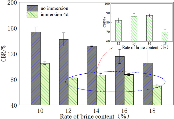
FIGURE 8. The change law of CBR of salt rock under different brine content.
Figure 8 shows that when the brine content gradually increased from 10% to 18%, the CBR value of the salt rock sample gradually decreased under the condition of non-immersion in brine. When the brine content was 18%, it was the lowest; at this time, the CBR was 105.6%, which showed a 31.3% decrease compared to 10%. Under the same dry density conditions, the mechanical properties decreased significantly with an increase in brine content. In terms of immersion conditions, the CBR values of the samples at different moisture contents showed a trend of first decreasing, increasing, and then decreasing after immersion for 4 days. Among them, the highest CBR value was at 10%, which was approximately 105.1%, and the lowest CBR value was at 18%, which was only 70.0%. However, when the brine content was 12%, 14%, and 16%, the difference in the CBR values of the samples was small, with the highest CBR value at 16%, which was approximately 87.6%. Compared with the non-immersion conditions, the decay of the CBR value at this time was the smallest. Therefore, when using salt rock as a roadbed filler for mixing, mixing based on the optimal brine content could help improve the bearing capacity of the roadbed under the most unfavorable flooding conditions. The Technical Specification for Construction of Highway Subgrades (JTG/T3610-2019) stipulated that the minimum CBR value of the upper roadbed filling was 8%. Therefore, the CBR value requirements for roadbed filler in the specifications were far met under various brine content ratios owing to the high salt content of the filler, which was prone to crystallization. Therefore, salt rock can be used as a filler for the entire structural layer of the roadbed.
Based on the experimental results, the p–l curves of salt rock samples with different brine contents and the rebound modulus are shown in Figure 9.
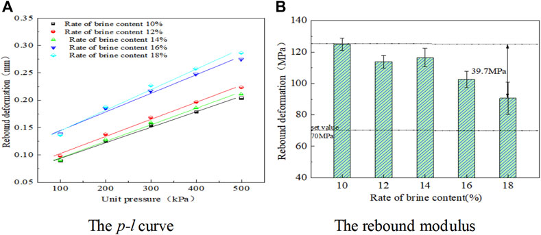
FIGURE 9. Changes law of rebound modulus of salt rock filler at different brine content.
Figure 9A shows that the higher the external load, the greater the rebound deformation generated by the sample. Within a certain range, the rebound deformation of the sample and the force showed a linear growth relationship. As the amount of brine mixed in the sample increased, the overall slope of the p–l curve showed a slight increase, indicating that the structural properties of the sample were improved by appropriately reducing the amount of brine mixed on the basis of the optimal brine content. However, their p–l curves did not intersect with the ordinate and the origin, which included a portion of plastic deformation. Therefore, when calculating the rebound modulus, corrections should be made. The analysis of Figure 9B shows that as the amount of mixed brine increased, the overall rebound modulus showed a decreasing trend. The change was insignificant when the brine content was between 10% and 14%. However, the rebound modulus significantly decreased when it was above 14%. However, under different brine contents, the rebound modulus of salt rock samples was higher than 90 MPa, which was higher than the 70 MPa requirement of the Technical Specifications for Design of Highway Asphalt Pavement (JTG D50-2017), indicating that salt rock had good mechanical strength when used as a roadbed filler. At the same time, during actual construction, the amount of brine sprayed should be appropriately reduced based on the optimal brine content to ensure that the roadbed has good bearing capacity under load.
The variation pattern of sample CBR with the compaction degree is shown in Figure 10. Figure 10A shows that as the penetration depth gradually increased, the growth slope of the stress penetration curve of salt rock under different compaction degrees first increased and then decreased. Moreover, as the compaction degree increased, the stress of salt rock increased faster under load, indicating that the lower the porosity between particles, the higher the compaction degree and the stronger the resistance to deformation of salt rock under load. In addition, Figure 10B shows that after immersion in water for 4 days, the stress levels of the salt rock samples showed varying degrees of attenuation under different compaction degrees. However, as the compaction degree increased, the unit pressure of the salt rock sample under load increased faster, indicating a decrease in the internal particle strength of the saturated sample. Moreover, due to the ion exchange effect of brine, the bonding state and internal voids between particles changed, resulting in a decrease in resistance to deformation. Based on the penetration and unit pressure relationship curves of salt rock samples under different compaction degrees, the variation pattern of CBR with the compaction degree under different working conditions was further obtained, as shown in Figure 11.
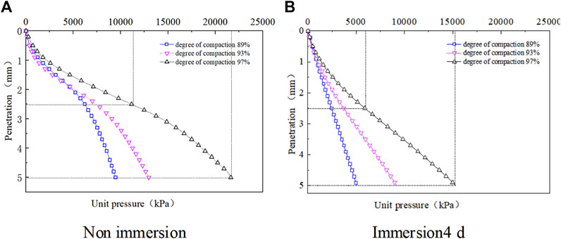
FIGURE 10. Penetration and unit pressure relationship curve.
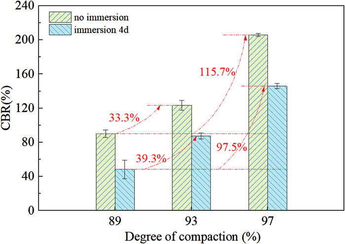
FIGURE 11. The Effect of Compaction on CBR of Salt Rock.
According to Figure 11, as the degree of compaction increased, the CBR of the salt rock sample gradually increased. The average CBR at 97% compaction degree was as high as 205.9%, and it increased by approximately one time compared to 89% compaction degree. The CBR value at a compaction degree of 89% was relatively low, only 90.2%, indicating that as the compaction degree increased, the soil structure became dense, and the bearing capacity of the sample continued to improve. After immersion in water for 4 days, the CBR values of the salt rock samples showed varying degrees of attenuation under different compaction degrees. Among them, when the degree of compaction was 89%, the strength of the sample decreased the most. At this time, the CBR value was approximately 48.3%, which decreased by approximately 46.4% compared to before immersion.
By testing the rebound deformation after compression, the p–l curve and rebound modulus of the sample were calculated. The influence of compaction on the rebound modulus is shown in Figure 12.
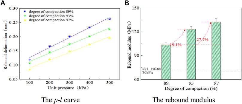
FIGURE 12. Influence of compaction degree on the rebound modulus of salt rock filler.
Figure 12A shows that the greater the compactness of the formed specimen during the test process, the smaller the rebound deformation generated by the specimen during the same load-loading and -unloading process. When the unit load was 100 kPa, the rebound deformation generated by the 97% compacted sample under the load was 0.084 mm, whereas the rebound deformation generated by the 89% compacted sample was 0.120 mm. In other words, the denser the structure, the lower the porosity and the stronger the resistance of the formed sample to external forces. As shown in Figure 12B, as the compaction degree gradually increased, the rebound modulus of salt rock gradually increased. Compared with the salt rock sample with a compaction degree of 97%, the rebound modulus increased by approximately 28.1 MPa when the compaction degree was 89%. Moreover, the rebound modulus of the salt rock sample was generally high, ranging from 100 to 130 MPa. When the compaction degree was 89%, the rebound modulus of the formed sample could meet the requirements for roadbed rebound modulus in the design specifications of an asphalt or cement concrete pavement (min. 70 MPa). Therefore, during construction, it was only necessary to ensure that the compaction of the salt rock filling roadbed met the specification requirements to obtain good bearing capacity.
Taking SC-20 graded salt rock fillers as the research object, the state diagram at different sample positions after immersion is shown in Table 3. The deformation rate of salt rock samples under different immersion times is shown in Figure 11, and the p–l curve of samples with different immersion times and non-immersion is shown in Figure 12.
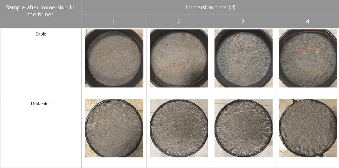
TABLE 3. State map of different positions of salt rock with 93% compaction degree after immersion.
According to Table 3, the top and bottom of the salt rock sample immersed in water for 1 day were in good condition, with only bleeding at the edges. After immersion in water for 2 days, a small amount of salt solution appeared on the top surface of the salt rock sample. The dissolution effect was significant at the edge of the bottom surface, and the overall degree of saturation was high. After immersion in water for 3 days, a certain number of pits appeared on the top surface of the sample, and pore water was filled. However, a large amount of salt rock was dissolved on the bottom surface, and pore water was supersaturated. The immersion condition had a prominent impact on the overall structural structure of the salt rock roadbed.
Figure 13 shows that under the influence of wetting by immersion, the water absorption and settlement phenomenon of the salt rock sample was more obvious in the early stage. After immersion in water for 2 days, the deformation amplitude of the sample’s settlement decreased. In the early stage of immersion, due to the dissolution of salts, the water absorption of the sample was relatively high. During this process, a large amount of ion exchange occurred between the salt in the brine and the easily soluble salt in the salt rock, causing the salt on the surface of the salt rock to dissolve and the particle strength to decrease. The sample was recompacted under load. After immersion in water for 3 days, the dissolution and ion exchange inside the sample gradually stabilized, and the degree of water absorption decreased. The pore water inside the sample gradually became saturated, and a thick water film formed around the particles. Due to the lubricating effect of the water film, the internal structure of the salt rock fillers underwent changes, specifically manifested as a decrease in the sample’s subsidence amplitude after immersion in water for 2 days. However, immersion in brine promoted the growth and healing of salt rock grains, which is one of the reasons for slowing down sample subsidence deformation.
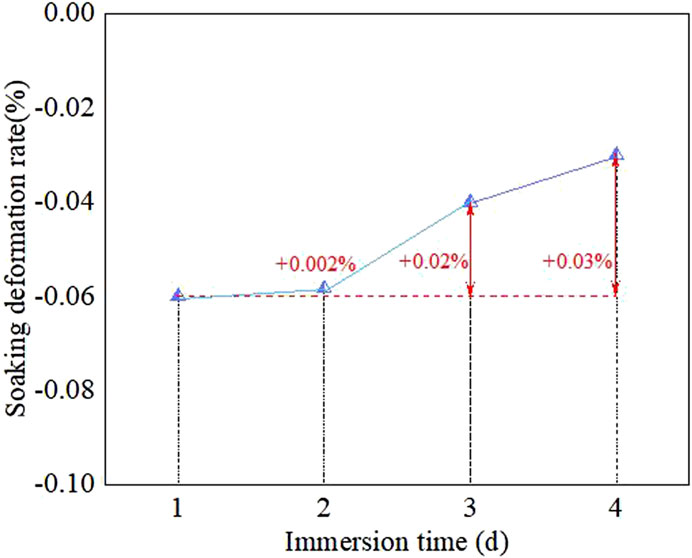
FIGURE 13. The variation law of immersion deformation rate with time.
Figure 14 shows that the rebound deformation of the sample gradually increased with an increase in the applied force. Within a certain range, the rebound deformation and the applied force showed a linear growth relationship. After immersion, the p–l curve was located on the upper side before immersion, and as the immersion time increased, the rebound deformation of the sample under the same load conditions showed an increasing trend. In addition, as the immersion time increased, the rebound deformation generated by the sample when receiving vertical pressure gradually increased. Under the influence of wetting by immersion, the overall structure of the sample was relatively poor, which is consistent with the state diagram of the bottom of the immersed sample in Table 3. After 1 day of immersion, the overall structure of the sample was good. After 2 days, local phenomena such as salt dissolution and aggregate peeling occurred on the bottom surface of the sample. In addition, after 3 days, the phenomenon of salt dissolution and peeling was more prominent, and the pore water showed supersaturation and a bleeding state.
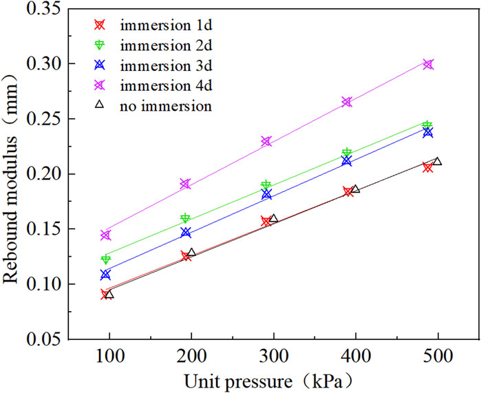
FIGURE 14. p-l curves of salt rock filler under different immersion times.
The penetration, pressure curve, and CBR calculation results of salt rock fillers under different immersion times are shown in Figure 15. As the penetration depth gradually increased, the slope of the unit pressure penetration curve of the salt rock sample before immersion first increased and then decreased. Under the immersion condition, the overall slope of the salt rock sample tended to stabilize with little variation, and its mechanical strength showed a significant decrease compared to the former. From the perspective of soil mechanics, penetration tests essentially reflected the local shear resistance of the soil. Cohesion was the main force that hindered the occurrence of shear deformation of particles, while internal friction played a hindrance role When part of the soil was displaced relative to the whole soil. From the curve of the immersion condition in Figure 15, the calculated CBR value was much smaller when the penetration was 2.5 mm than before immersion, with a decrease of 43.1% in CBR after 1 day of immersion compared to before immersion. Water film formed around the particles after the sample was saturated greatly reduced the internal friction force between the particles. During the process of increasing the penetration amount to 5 mm, the penetration stress values after 3–4 days of immersion gradually decreased compared to those after 1–2 days of immersion. When immersed for 4 days, the CBR value was approximately 71.2%, a decrease of approximately 34.0% compared to before immersion. However, it met the CBR value requirements for roadbed filler in the specifications (min 8%).

FIGURE 15. Changes in CBR of salt rock under different immersion times.
According to Figure 16, as the immersion time increased, the rebound modulus of the salt rock sample showed a significant downward trend. In the early stages of immersion (1 and 2 days), the performance degradation amplitude was relatively small, and after 3 days of saturation, the attenuation amplitude was more severe. Among them, the rebound modulus attenuation amplitude was 5.5% after 2 days of immersion, whereas the rebound modulus attenuation amplitude was as high as 25.6% after 4 days of immersion. All the aforementioned situations could meet the requirements for subgrade rebound modulus (min. 70 MPa) in the design specifications for an asphalt or cement concrete pavement.
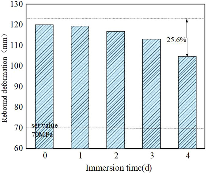
FIGURE 16. Change in rebound modulus of salt rock under different immersion times.
The test data of the CBR value of salt rock fillers under different brine contents, compaction degrees, and immersion times were combed and summarized. After determining the parameters, the regression model relationship was outputted. As shown in Formula (11), the relationship between each estimated value and the actual value is shown in Figure 17A, and the fitting effect is good. The CBR of salt rock fillers was well predicted:
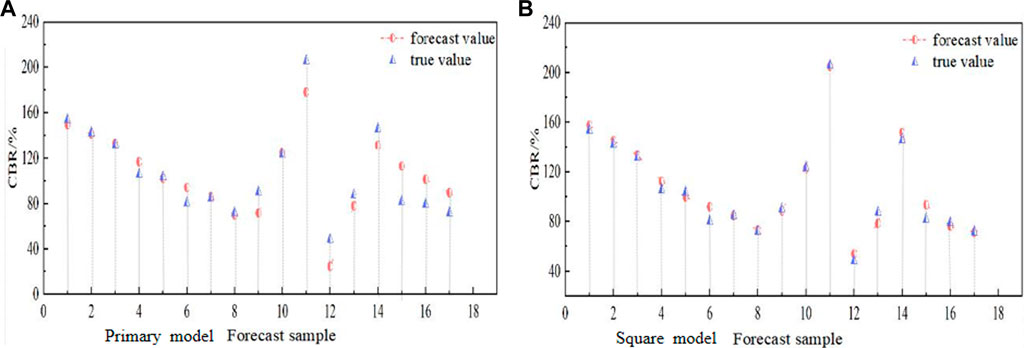
FIGURE 17. Forecast sample.
The relationship between the output square regression model is shown in Formula (12), and the relationships between the estimated and actual values are shown in Figure 17B. The R2 is 0.981, and the fitting effect is better than the primary regression model, which can better predict the CBR of salt rock fillers:
Inverse normalization on the estimated data was performed, the inverse parameters c and g were trained multiple times to improve model accuracy, and finally all output results were visualized in software, as shown in Figure 18.
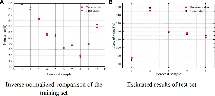
FIGURE 18. Comparison diagram of SVM forecast model for bearing ratio of salt rock filler.
Based on the experimental data from Section 3.2.2, Section 3.3.2, and Section 3.4.3, the rebound modulus values of salt rock fillers under different brine contents, compaction degrees, and immersion times were sorted and summarized. After determining the parameters, the regression model relationship was outputted as shown in Formula (13), and the relationships between each estimated value and the actual value are shown in Figure 19A. The R2 of the models is 0.564, and the value of the neural network and actual value have good fitting results. The rebound modulus of salt rock fillers is well predicted:
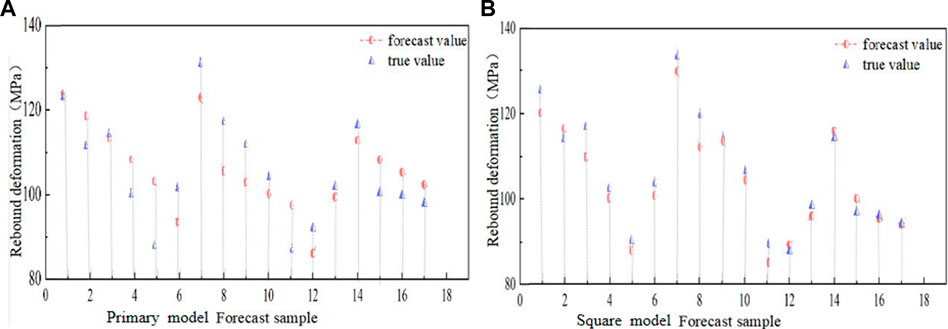
FIGURE 19. Comparison between estimated and actual values.
The relationship of the output square regression model is shown in Formula (14), and the relationship between each estimated value and the actual value is shown in Figure 19B. R2 of 0.981 is better than the quadratic regression model to better estimate the rebound modulus of salt rock fillers:
When establishing a model for evaluating the influencing factors of salt rock fillers’ rebound, the selection of input layer indicators and mapping layer functions is the same as the aforementioned method, and the output item is changed to the rebound modulus indicator. Follow the aforementioned methods for training and testing in sequence, and the visualization results are shown in Figure 20.
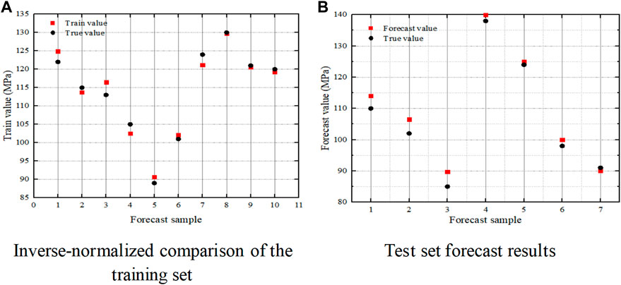
FIGURE 20. Forecast model of salt rock filler rebound modulus SVM.
According to the commonly used calculation for forecast error indicators in Formulas 15–17, the aforementioned three regression models were used to organize the CBR value, rebound modulus forecast value, and corresponding actual values of salt rock fillers. The corresponding error indicators R2, RMSE, MAE, and MAPE values were comprehensively compared and analyzed, as shown in Figures 21, 22:
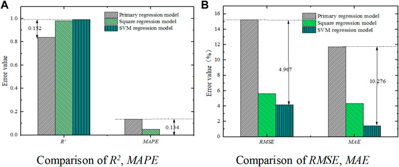
FIGURE 21. Comparison diagram of CBR value multi-model forecast error indicators.
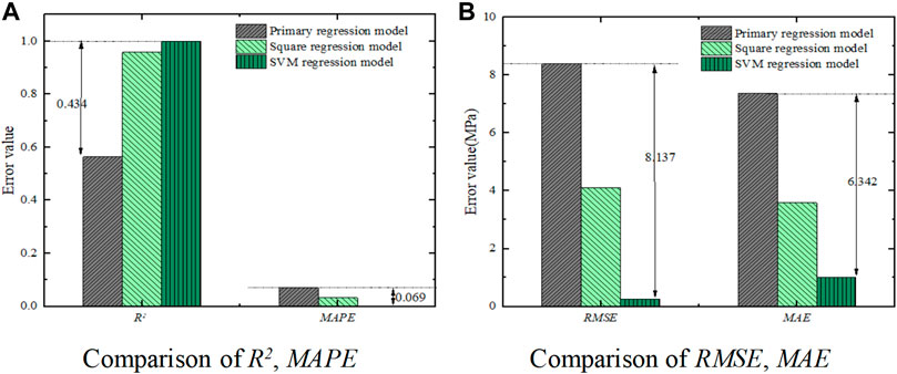
FIGURE 22. Comparison of rebound modulus multi-model prediction error indicators.
As shown in Figure 21, the SVM regression model showed the highest correlation coefficient R2 (0.991) in the estimated CBR value of salt rock fillers, which was 0.152 higher than the R2 of the primary regression model, indicating that the SVM regression model had the best fitting correlation. The values of error indicators MAPE, RMSE, and MAE of the SVM regression model were much smaller than those of the primary and square regression models, which were 0.134, 4.967, and 10.276 lower than the highest values, respectively, indicating that it had better forecast accuracy.
Similarly, Figure 22 shows that the comparison effect of the error indicators in predicting the rebound modulus showed the same trend. The correlation coefficient R2 (0.998) of the SVM regression model was higher than that of the primary regression model by 0.434, and the error indicators MAPE, RMSE, and MAE were 0.069, 8.137, and 6.342 lower than the highest value. The forecast results were closer to the actual value, and the forecast effect improved. Moreover, there were many parameters in the primary and square regression models, making the calculation process cumbersome and prone to errors. The SVM regression model can directly perform forecast calculations without manually inputting parameters, thus avoiding this problem. In summary, for the CBR value and rebound modulus indicators of salt rock fillers, the SVM nonlinear regression model is recommended for the mechanical index forecast. Based on a more accurate forecast effect, it is easy to control construction parameters and ensure the bearing capacity, strength, and stability of salt rock filler roadbeds.
The influencing factors on the compaction characteristics of salt rock fillers were explored, and the effects of factors such as brine content, compaction degree, and immersion time on the mechanical properties of salt rock fillers were comprehensively studied. Three forecast models for the mechanical properties were constructed, and the optimal forecast model was recommended. The main conclusions are as follows:
(1) The optimal brine content of salt rock fillers with different gradations was approximately 8.2%–9.3%, and SC-10 salt rock had the highest optimal brine content. The dry density of salt rock fillers under different grades was approximately 1.69–1.76 g/cm3.
(2) As the brine content increased, the CBR of salt rock samples in the non-immersion state gradually decreased, maintaining an overall range of 70%–105.1%. At the same time, the resistance to external force deformation of the samples gradually decreased. The rebound modulus of salt rock samples with different brine contents was higher than 90.6 MPa.
(3) Under different immersion conditions, the CBR increased with the degree of compaction. As the degree of compaction increased from 89% to 97%, the CBR of non-immersion samples increased from 90.2% to 205.9%, and the CBR of immersion samples increased from 48.3% to 145.8%. At the same time, the ability to resist external force deformation was significantly improved. When the compaction degree increased from 89% to 97%, the rebound modulus of salt rock samples increased by approximately 28.1 MPa.
(4) As the immersion time increased, the CBR of the salt rock sample gradually decreased. The performance degradation amplitude of the rebound modulus was relatively low in the early stage of immersion, but the change was more significant after 3 days.
(5) The SVM regression model had the highest forecast accuracy index R2, and the error-index MAPE, RMSE, and MAE values were much smaller than the other two regression models. It was recommended to use the SVM regression model as a forecast model for the mechanical properties of salt rock.
In the subsequent step, a control model of salt rock engineering properties coupled with temperature, corrosion, seepage, and stress can be established to provide the theoretical basis for a comprehensive analysis of the stability of salt rock fillers.
The original contributions presented in the study are included in the article/Supplementary Material. Further inquiries can be directed to the corresponding authors.
CC: writing—original draft preparation, investigation, and formal analysis. JL: conceptualization, supervision, and resources. CW: conducting the experiments. LS: methodology. HC and LS: writing—review and editing. All authors contributed to the article and approved the submitted version.
This research was supported by the Key Science and Technology Program in the Transportation Industry (2019-MS1-024) and Transportation Department Science and Technology Project in Xinjiang Uygur Autonomous Region (2019-ZD1-015).
The authors are grateful for the support.
LS was employed by the company Xinjiang Communications Investment Construction Management Co., Ltd. and Xinjiang Transportation Planning Surveying and Design Institute Co., Ltd.
The remaining authors declare that the research was conducted in the absence of any commercial or financial relationships that could be construed as a potential conflict of interest.
All claims expressed in this article are solely those of the authors and do not necessarily represent those of their affiliated organizations, or those of the publisher, the editors, and the reviewers. Any product that may be evaluated in this article, or claim that may be made by its manufacturer, is not guaranteed or endorsed by the publisher.
Cheng, L., Li, J. F., Yi, R., Liang, C., and Liao, Y. (2021). Study on very long-term creep tests and nonlinear creep-damage constitutive model of salt rock. Int. J. Rock Mech. Min. 146, 104873. doi:10.1016/j.ijrmms.2021.104873
Fan, J. Y., Jiang, D. Y., Liu, W., Wu, F., Chen, J., and Daemen, J. (2019). Discontinuous fatigue of salt rock with low-stress intervals. Int. J. rock Mech. Min. 15, 77–86. doi:10.1016/j.ijrmms.2019.01.013
Gao, B. L., Wang, J. C., and Li, Y. (2015). Research on the salt soluble disasters of saline lake subgrade along the Qinghai-Tibet railway in Chaerhan salt lake region. J. Railw. Engin 5, 6–11+17.
Huang, X. H., Zhang, X., and Li, Z. (2019). Study on grain composition of manufactured sand on basis of Fuller and Tabor theory. Concrete 354 (04), 97–101.
Kang, M. Y., Zhu, Y. Q., and Chen, C. (2022). Research on landslide sliding distance prediction moded based on multiple nonlinear regression and BP neural network. Geolo Bulle China 12, 2281–2289.
Li, H. L., Yang, S. Y., and Si, J. Z. (2023). Evaluation of asphalt pavement performance based on AMPSO-SVM. J. Dalian Univ. Technol. 63 (01), 69–76.
Li, Z., Zhang, J. P., Liu, T., Wang, Y., Pei, J., and Wang, P. (2021). Using PSO-SVR algorithm to predict asphalt pavement performance. J. Perform. Constr. Fac. 35 (6), 1–12. doi:10.1061/(asce)cf.1943-5509.0001666
Li, Z. Z., Jiang, D. Y., and Fan, J. Y. (2021). Experimental study of triaxial interval fatigue of salt rock. Rock Soil Mech. 04, 1305–1312+1322.
Li, Z. Z., Kang, Y. Y., Fan, J. Y., Fourmeau, M., Jiang, D., and Nelias, D. (2023). Creep–fatigue mechanical characteristics of salt rocks under triaxial loading: an experimental study. Eng. Geol. 322, 107175. doi:10.1016/j.enggeo.2023.107175
Lv, S. S., Ni, W., and Ni, H. J. (2020). Hydrolysis behavior of AlN in aluminum dross and its multivariate nonlinear regression analysis. China J. Rock Mech. Engin 4, 920–926.
Moazenian, A. R., and Abedi, F. (2021). Determining the mechanical characteristics of prismatic salt rock samples and comparing them with cylindrical Ones. J. Min. SCI+. 3, 405–413. doi:10.1134/s1062739121030066
Pedro, M., Maria, L. A., Eduardo, F., and Gomes, M. C. (2021). Machine learning approach for pavement performance prediction. Int. J. Pavement Eng. 22 (3), 341–354. doi:10.1080/10298436.2019.1609673
Song, L., Niu, L. L., and Wang, Z. H. (2018). Advances in engineering characteristics in salt rock subgrade. Highw. Eng. 6, 156–162.
Wang, C. H., Chen, S. C., Song, L., and Wang, L. J. (2023). Microbial production of mevalonate. Chin. J. Geotechnical Eng. 370, 1–11. doi:10.1016/j.jbiotec.2023.05.005
Wang, J., Zhang, Q., Song, Z., and Zhang, Y. (2020). Creep properties and damage constitutive model of salt rock under uniaxial compression. Int. J. Damage Mech. 29 (6), 902–922. doi:10.1177/1056789519891768
Wang, S., Li, Y. L., and Li, Q. (2022). Influence of gangue gradation coefficient on the performance of filling material based on Talbol theory. J. Min. Saf. Eng. 39 (04), 683–692.
Xi, H., Chen, H. Y., and Song, L. (2022). Construction process optimization and stability monitoring of Lop Nor salt rock subgrade. Highway 67 (07), 21–27.
Xu, S. R. (2017). Research on parameter optimization algorithm of hybrid kernel function support vector machines. J. Heze Univ. 5, 20–28.
Zhang, J. H., Peng, J. H., Liu, W. Z., and Lu, W. (2019). Predicting resilient modulus of fine-grained subgrade soils considering relative compaction and matric suction. Road. Mater Pavement 1, 703–715. doi:10.1080/14680629.2019.1651756
Keywords: subgrade engineering, salt rock fillers, California bearing ratio, rebound modulus, forecast model
Citation: Cheng C, Liu J, Wang C, Song L and Chen H (2023) Mechanical properties of Lop Nor salt rock fillers for subgrade and its forecast model construction. Front. Mater. 10:1245955. doi: 10.3389/fmats.2023.1245955
Received: 24 June 2023; Accepted: 02 August 2023;
Published: 01 September 2023.
Edited by:
Xiaolong Sun, Guangdong University of Technology, ChinaReviewed by:
Guoqiang Sun, Beijing University of Technology, ChinaCopyright © 2023 Cheng, Liu, Wang, Song and Chen. This is an open-access article distributed under the terms of the Creative Commons Attribution License (CC BY). The use, distribution or reproduction in other forums is permitted, provided the original author(s) and the copyright owner(s) are credited and that the original publication in this journal is cited, in accordance with accepted academic practice. No use, distribution or reproduction is permitted which does not comply with these terms.
*Correspondence: Jie Liu, MjAyMTAyMTA5MUBjaGQuZWR1LmNu; Chaohui Wang, d2NoaDAyMDVAY2hkLmVkdS5jbg==
Disclaimer: All claims expressed in this article are solely those of the authors and do not necessarily represent those of their affiliated organizations, or those of the publisher, the editors and the reviewers. Any product that may be evaluated in this article or claim that may be made by its manufacturer is not guaranteed or endorsed by the publisher.
Research integrity at Frontiers
Learn more about the work of our research integrity team to safeguard the quality of each article we publish.