 Zengwen Wu
 Ce Li2
 Gang Liu
94% of researchers rate our articles as excellent or good
Learn more about the work of our research integrity team to safeguard the quality of each article we publish.
Find out more
ORIGINAL RESEARCH article
Front. Mater., 04 August 2023
Sec. Thin Solid Films
Volume 10 - 2023 | https://doi.org/10.3389/fmats.2023.1240638
Free-edge effect is one of the factors affecting the mechanical properties of three-dimensional woven composites under tensile load. However, current research is relatively poorly understood regarding the effect of free-edge on the stiffness and strength of the material. This paper aims at examining the influence of free-edge effect on the mechanical properties of 3D woven composites under tension through experimental and simulation methods. The three-dimensional digital image correlation (DIC) technique is used to collect the full-field strains on the specimen surface during the test, and the stress-strain differences in different regions in the width direction are analyzed, and the overlap of the curves in each region is found to be high, indicating that the boundary effect has a small influence on the tensile properties of 3D woven composites. Experimental studies are conducted on specimens of different widths (within the range of 15–20 mm), and the results indicate that the differences in mechanical properties of 3D woven composites under tension loading in this width range are not significant. A progressive damage finite element model is developed for calculation and compared with experimental results. It is found that the tensile properties of the material decreased when the width of the specimen is less than twice the size of the single cell. This study can provide certain data support for the study of the mechanical properties of 3D woven composites and enable the subsequent more in-depth study to provide a certain foundation.
In the fields of aerospace and shipbuilding, fiber-reinforced composites are extensively used due to their exceptional mechanical characteristics, including high specific stiffness and specific strength. These composites are frequently subjected to tensile forces, and scientists have investigated and examined their tensile properties.
Tensile property is a significant mechanical feature of fiber-reinforced composites, which are excellent engineering materials, and scholars studied this property in depth from various aspects (Kohlman et al., 2012; Deng et al., 2021; Liu et al., 2023). Hang et al., (2021) researched the damage and deformation of 2.5D woven composites under tensile loading through a micro/mesoscale analytical framework, analyzed and predicted the strength and elastic properties of fiber bundles, and verified them by comparing with experimental results.
Researchers have conducted numerous early studies on the free-edge effect of composite laminates and found that in many cases the difference in Poisson’s ratio between adjacent plies can lead to laminate free-edge damage (Mittelstedt and Becker, 2004). The study of the free edge effect in woven composites is further complicated by the presence of inhomogeneous deformation within the single cell (Kohlman, 2012).
Chao et al., (2015) focused on the effect of free-edge effect on the feedback of triaxial woven composites under tensile loading and the effect of different specimen widths on the tangential modulus and breaking strength of the material in transverse tension. Finally, the free-edge periodic distribution law was obtained and the relationship between the effective modulus and the specimen width was quantified.
Researchers investigated ways to enhance the mechanical properties of composites by dealing with the free-edge effect. Brauning et al., (2021) adopted a method of treating the edges of composite sheets with a high-performance adhesive to eliminate the free-edge effect and demonstrated that the method was effective in improving the tensile properties by about 11%.
The influence of the geometry of the specimen on the properties of the composite is also not negligible (Kueh, 2014; Flauder et al., 2021). Li et al., (2021) found through experimental studies that different preparation angles have significant effects on the tensile properties and damage mechanisms of 3D braided composites. Laux et al., (2020) used a new modified fixture for combined loading to investigate the difference in the performance of three laminates with the same size and elastic properties and different layup size and layup orientation angles under combined loading. The study by Cai et al., (2021) on the free-edge effect of triaxially woven composites found that the damage mechanism changed from fiber bundle pullout to fiber bundle shear as the specimen width increased.
Relatively little research was reported on the free-edge effect on the tensile properties of 3D woven composites, because of the complex and diverse internal weaving forms of three-dimensional woven composites, diverse weaving patterns lead to different material properties (Zhou et al., 2021; Jiao et al., 2020), there is a necessity to study more comprehensively and extensively on the free-edge effect of 3D woven composites.
In this paper, the free edge effect of 3D woven composites has been investigated by analyzing the tensile properties of specimens with different width regions and different sizes using both experimental and simulation methods. The three-dimensional digital image correlation (3D DIC) technique is used to observe the process in order to collect the distribution of full-field strain on the surface of material. The strain variation in different regions along the width of the specimen during the tensile process is analyzed, and the effect of width on the tensile properties of the material is investigated ensuring that the width of the specimen is greater than two single cell dimensions, and the variation of tensile strength, tensile modulus and failure strain are analyzed. The affect of the free-edge effect on the tensile properties of the material is predicted by using a progressive damage finite element model.
Three-dimensional woven composite is one of the typical non-uniform anisotropic material composed of fiber reinforcement and resin matrix, whose internal fiber bundles include warp fiber bundles, weft fiber bundles and Z-directional fiber bundles, which form a fiber reinforcement by complex and diverse winding forms between them. 3D woven composites are classified into three categories: orthogonal woven, angle-interlocked woven and inter-layered interlocked woven composites, depending on their Z-directional fiber bundle winding methods.
The material used in this study is an interlocking three-dimensional woven composite material provided by the Institute of Composites Structure of Tianjin University of Technology. The material is composed of two types of fiber bundles and an epoxy resin matrix, Toray 12K-T700SC for the warp and weft fiber bundle types, Toray 3K-T300SC for the Z-direction fiber bundle type, and TDE-86 for the epoxy resin matrix type. The production method of this material board is RTM molding process. The basic mechanical properties of the fine component materials of the composites are shown in Table 1. The thickness of the material sheet is 5 mm, in which there are 8 layers of warp fiber bundles and 9 layers of weft fiber bundles, and Z-directional fiber bundles are interspersed between the warp fiber bundles and link the layers of weft fiber bundles as a whole. The structure schematic diagram of the material is shown in Figure 1. The distribution of component materials of 3D woven composites has a certain periodicity, so the material plate can be regarded as a whole consisting of a single cell arrangement of component materials within a certain range.
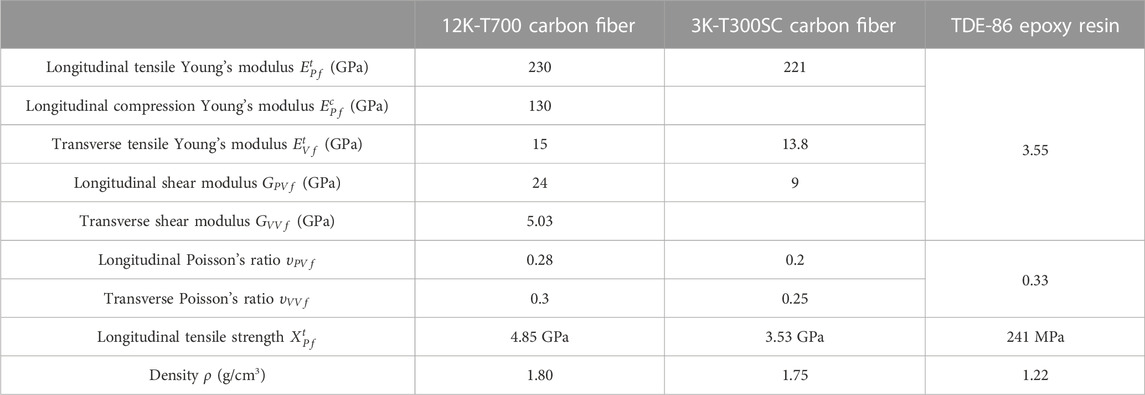
TABLE 1. Basic mechanical properties of the constituents.

FIGURE 1. The structure diagram of 3D woven composites.
As an advanced composite material, the American Society for Testing and Materials (ASTM) developed some test standards for fiber-reinforced composites under quasi-static loading in the early years. The reference standard for the quasi-static uniaxial tension study of 3D woven composites in this paper is ASTM D 3039/D 3039M-08 (ASTM_International, 2008).
According to the statistics of the surface structure of the material, the width of the cell is about 6–7 mm. In order to ensure that there are at least two complete cells in the specimen width, the specimen width is set to 20 mm when studying the boundary effect and 15–20 mm (15, 17.5, and 20 mm) when studying the dimensional effect of the specimen, and the specimen size and shape are shown in Figure 2. The method applied to cut the specimens is waterjet cutting, which is to avoid the high temperature generated by the traditional cutting methods during the process and affect the performance of the material, while ensuring the cutting accuracy. To reduce the early damage of the specimen caused by the stress concentration in the clamping part at both ends of the specimen, and to increase the clamping friction to prevent the slippage of the specimen during the test, the clamping part at both ends of the specimen is polished smooth and a reinforced aluminum sheet with a thickness of 2 mm and a length of 65 mm is pasted, and the effective length of the specimen is 120 mm.
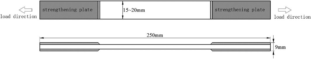
FIGURE 2. Uniaxial tensile specimen of 3D woven composites.
The uniaxial tensile experiment is conducted at room temperature, and loaded by Lishi—250 kN Servo-Hydraulic Fatigue Testing Machine. The loading method is displacement-controlled loading with a rate of 0.5 mm/min.
A non-contact, full-field strain measurement system developed using digital image correlation (DIC) technology can be used to capture the optical scatter on the surface of the object to be measured, track the displacement data at each point on the surface, and calculate the strain and other data. Compared with the traditional contact strain measurement method, the DIC system has the advantages of no impact on the experimental process due to the actual contact with the specimen, high accuracy, and ease of use, etc. The 3D DIC system establishes a 3D spatial coordinate system in the field of view by obtaining spatial information between cameras through the calibration process. The 3D DIC system can calculate the displacement and strain in one more direction than the 2D DIC system, and the strain obtained by the 3D DIC system can eliminate the fake strain caused by the off-surface movement of the specimen during the experiment when calculating the plane strain.
To obtain the full-field strain on the surface of the test piece during the tensile experiment, the experimental setup shown in Figure 3 is built in this study. The surface of the specimen is photographed with two mutually angled (5°–10° is appropriate) fixed-focus camera lenses, and the two cameras are connected to the image acquisition system, and the shooting frequency is set to 2 Hz, i.e., each camera takes two pictures per second. Clamp the specimen in the upper and lower chuck of the test machine, according to the range of the camera, adjust the distance between the camera and the specimen, the angle between the two cameras to focus, to ensure that the image acquisition system to obtain a clear picture, if necessary, LED lights can be used for lighting compensation. Then, with the help of calibration board, several sets of images with different postures and azimuth angles are taken by two cameras at the same time, which are used as the parameters of the VIC-3D analysis software to calibrate the relative positions of the cameras, so that the real strain field on the surface of the specimen can be obtained.
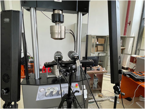
FIGURE 3. Setup of 3D DIC technology.
In order to study the boundary effect of the material, the DIC technique is used to obtain the full-field strain information on the specimen surface during the uniaxial tension of the 3D woven composite. The full-field strains on the specimen surface at different moments are shown in Figure 4, and the numbers on the right side of Figure 4 (1) to (16) are the average strains in the effective area of the specimen surface corresponding to different moments. It can be seen that during the change from the average strain of 1,557–16,481, the strain along the latitudinal direction of the specimen surface is basically the same at each moment, and the overall strain is relatively uniform, which indicates to a certain extent that the boundary effect of the specimen is not obvious.
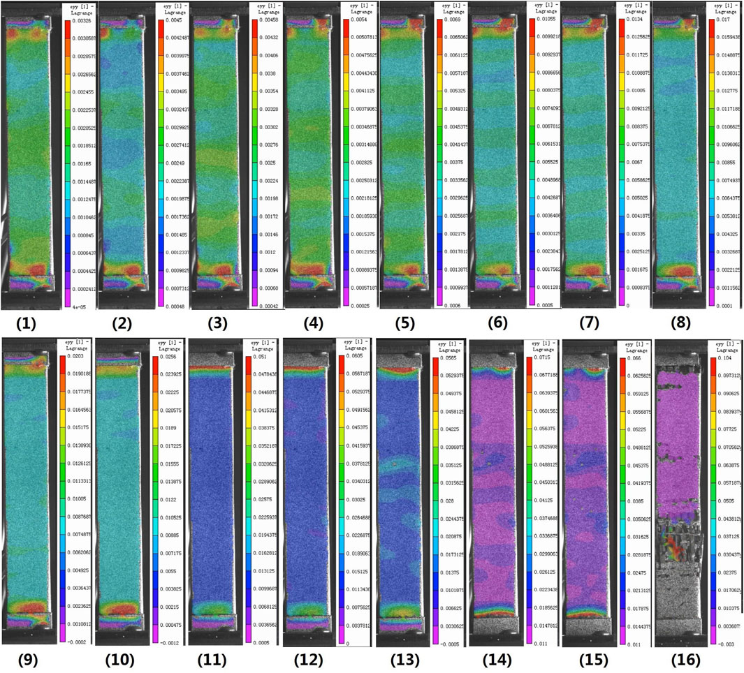
FIGURE 4. Surface strain nephogram of specimen during uniaxial tension.
With the purpose of further studying the influence of the specimen boundary on the overall performance. The strain information of six different regions on the specimen surface are extracted separately, and the average stress-strain curves of different regions are obtained, as shown in Figure 5. The colored square areas in Figure 5A represent the selected five small areas at different locations, and the black area represents the middle large area with the boundary removed. The average stress-strain curves of these six regions are given in Figure 5B. It can be found that the stress-strain curves of these six regions basically overlap before the specimens fracture, indicating that the boundary effect of the test piece does not have much influence on the macroscopic properties of the material. Therefore, in order to save materials and ensure more reliable experimental results, the width of the test piece is selected as 20 mm.
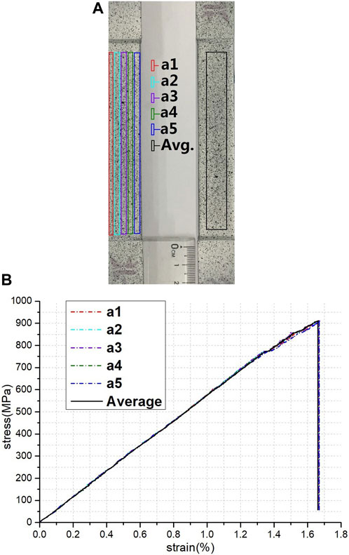
FIGURE 5. Boundary effect analysis of uniaxial tension (A) schematic diagram for selecting different areas on the surface of a specimen (B) stress-strain curves of different area.
The material in this study is brittle and the fiber damage occurs only when the critical load is approached. The surface strains were all small and the matrix shedding was minimal before damage, and there was no significant difference in the distribution in the width direction.
In this study, tensile experimental studies are conducted on three different widths (20, 17.5, and 15 mm, respectively) to investigate the effect of specimen size on the experimental results, and macroscopic stress-strain curves are obtained for the three widths, as shown in Figure 6. It can be seen by comparison that the results of the experiment are in accordance with the results reported in the literature (Liu et al., 2019).
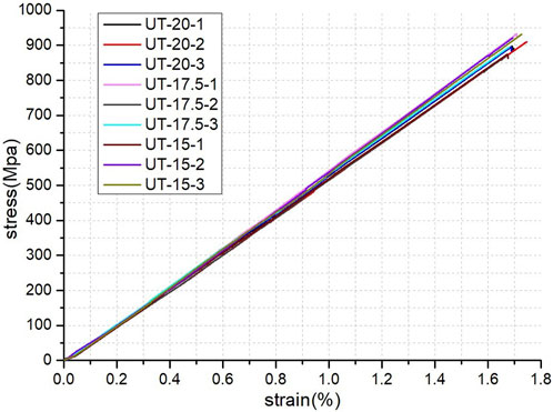
FIGURE 6. Stress-strain curves of specimens with different widths.
As can be seen, the dispersion of the stress-strain curves of the three sizes of test pieces is quite minor. The tension experiment results of the three sizes of test pieces are given in Table 2, and it can be observed that the average elastic modulus, average tensile strength and average failure strain of the three sizes are generally consistent, and the dispersion coefficient of the tension results of the three sizes of test pieces is less than 0.03, which indicates that the size effect of the three-dimensional woven composite specimens is not obvious between 15 and 20 mm in width.
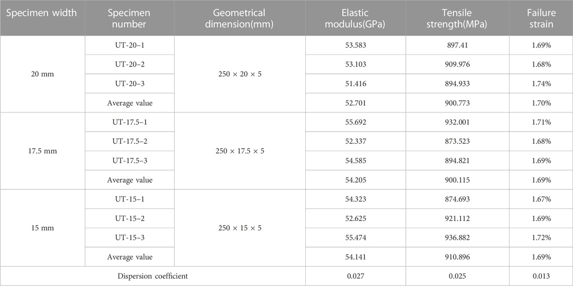
TABLE 2. Uniaxial tensile experimental data of specimens with different widths.
In this paper, a progressive damage finite element model is also developed to investigate the effect of free-edge effect on the tensile properties of 3D woven composites (Liu et al., 2019). The VUMAT subroutine based on ABAQUS software was written to implement the determination and evolution of material damage. A inhomogeneous finite element method was used, where material properties are determined by the location of integration points during the calculation. Instead of distinguishing between fiber bundles and matrix, different material properties are used by determining the type of component material at the integration point location, thus avoiding the difficulty of meshing fiber bundles and matrix separately. An exponential model is used to discount the material properties during the damage evolution. The macroscopic full-size model is established according to the test dimensions, and the schematic diagram of the model is shown in Figure 7. Based on the statistics of the geometric dimensions of warp and weft yarns and binder yarns and simplified, the yarn is designed as an octagonal cross-section with a warp and weft yarn width of 1.483 mm and a binder yarn width of 0.7415 mm. The fiber volume fraction is 50.9%, which is the same to the actual 3D composite material.
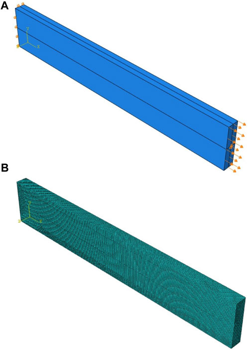
FIGURE 7. Schematic diagram of finite element model (A) load condition (B) mesh.
The mesh is divided into positive hexahedral cells with a mesh size of 0.5 mm, and the cell type is an eight-node reduced integral cell (C3D8R), and the boundary conditions are imposed according to the real force conditions during the test to simulate the damage failure behavior of 3D woven composite materials under tensile loading.
To describe the different fracture modes in three-dimensional woven composites, a modified Puck criterion is used to determine the damage and development of fiber bundles and a parabolic criterion to serve as a matrix damage criterion in this model. The present constitutive equation can be expressed as:
where f and m respectively denote the fiber bundle and matrix,
The damage factor matric of fiber yarn can be written as:
The damage factor matric of matrix can be written as:
Where
The initial compliance matric of the fiber yarn can be written as:
The initial compliance matric of the matrix can be written as:
Where
The damage initiation and evolution criteria of matrix and fiber yarn are defined as:
Where
The damage and failure behaviors of the 3D woven composite under uniaxial tensile loading are obtained by the above finite element model calculation, and the final damage schematic is shown in Figure 8. The final damage and failure of the finite element model shows that the final failure is severe at a certain cross-section of the model midsection and a large number of units fail, which is consistent with the actual material failure.
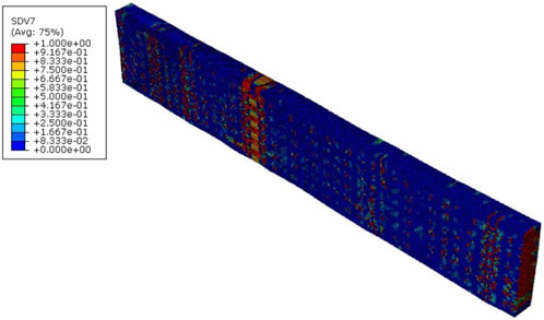
FIGURE 8. Final damage diagram of finite element model.
Different regions are divided according to the width direction of the specimen, and the stress-strain curves are extracted separately, as shown in Figure 9. The stress-strain curves in the model in the figure for different regions along the width direction show that the curves in each region largely overlap before the material fails and damages. This indicates that the mechanical properties of the edge and middle regions of the material under tensile loading are basically the same.
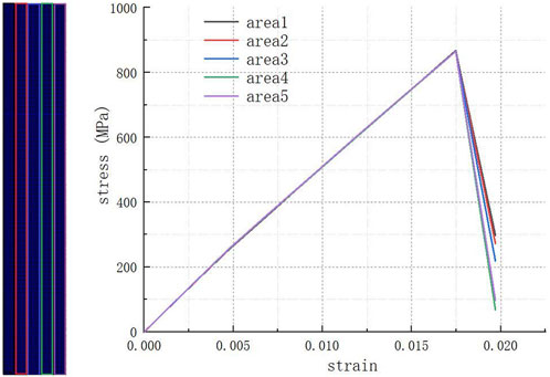
FIGURE 9. Comparison of stress-strain curves in different areas.
It can be seen that the final damage situation obtained from the simulation is consistent with the damage situation obtained from the test, and the test and simulation curves basically match, indicating that the model can effectively predict the failure and surface strain distribution of the 3D woven composite under uniaxial tensile loading. Meanwhile, comparing the model calculation results with the literature (Liu et al., 2019) shows that the model can predict the mechanical properties of three-dimensional woven composites under tensile loading more accurately.
The tensile properties of the specimens with different widths are obtained and the data extracted by changing the model width through the above model calculations. The obtained calculation results are shown in Table 3, which shows that when the specimen width is reduced from 15 to 8 mm, the tensile strength of the material is reduced. When the width of the specimen is in the range of 15–20 mm, the tensile strength of the specimen does not change more than 1%. The tensile strength of the composite continued to increase as the specimen width became larger to 25 mm. Meanwhile, the failure strain and modulus of elasticity did not vary much with the specimen width.

TABLE 3. Simulation results of tensile properties of specimens with different widths.
From Figure 10, in the width range of 15–20 mm, the failure strain, elastic modulus and tensile strength of the material vary somewhat but are within a reasonable range. When the specimen width is less than 15 mm, the mechanical properties of the material under tensile load are somewhat weakened with the decrease of the specimen width. The results of this study are consistent with the conclusions obtained in the literature (Cai et al., 2021).
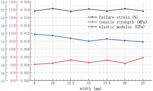
FIGURE 10. Finite element simulation results of tensile properties for different width models.
The reason for this phenomenon is that the three-dimensional woven composites are assembled by the arrangement of single cells, and when the width of the specimen is smaller than the size of two single cells, the mechanical properties of the material under tensile loading are reduced.
When the specimen size is smaller than two single cell sizes, the proportion of fiber bundles parallel to the direction of tensile load may be reduced due to the randomness of the position of the specimen when it is cut from the material plate. The tensile properties of the material therefore become unstable at this time, and it is reasonable that the tensile properties are reduced.
In order to study the free-edge effect of three-dimensional woven composites under uniaxial tension, the 3D DIC system is used in this paper to collect and analyze the full-field strain of the specimens during the test, and the tensile experiments are studied for specimens of different widths on the basis of ensuring that the width of the specimens is larger than two single cell sizes, and the following conclusions are obtained:
1. Under the uniaxial tension, the surface strain changes of the three-dimensional woven composites are generally consistent and uniformly distributed along the width direction, and the stress-strain curves of the specimens in different areas along the width direction are in good agreement, indicating that the boundary effect has a small effect on the tensile properties of the three-dimensional woven composites.
2. The stress-strain curves of the three-dimensional woven composite specimens with different widths (15–20 mm) under uniaxial tensile loading overlap well, and the average elastic modulus, average tensile strength and average failure strain dispersion coefficients of the three types of specimens are less than 0.03, demonstrating that the size effect of the specimens in this width range is not obvious.
3. By using the progressive damage finite element model, it is found that the stress-strain curves in different regions of the same specimen width direction under tensile loading of three-dimensional woven composites basically the same, and are not greatly affected by boundary effects. and the mechanical properties of different width specimens have not much change. When the width of the specimen is less than twice the size of the single cell, the tensile mechanical properties of the material are decreased.
The datasets presented in this article are not readily available because the raw data will be used to publish additional articles. Requests to access the datasets should be directed to GL, bGl1Z0BlY2p0dS5lZHUuY24=.
Conceptualization, ZW; methodology, GL; software, CL; validation, ZW and FL; formal analysis, SZ; investigation, CL; resources, GL; data curation, FL; writing–original draft preparation, CL; writing–review and editing, GL; visualization, FL; supervision, ZW; project administration, SZ; funding acquisition, ZW, GL, and SZ. All authors contributed to the article and approved the submitted version.
This research was funded by the National Natural Science Foundation of China (No. 12102215), the Natural Science Foundation of Zhejiang Province (No. LQ21A020001), the Jiangxi Provincial Natural Science Foundation (Grant Nos 20212BAB211007 and 20202BAB211005), Department of Education of Jiangxi Province (Grant No. GJJ190328).
The authors declare that the research was conducted in the absence of any commercial or financial relationships that could be construed as a potential conflict of interest.
All claims expressed in this article are solely those of the authors and do not necessarily represent those of their affiliated organizations, or those of the publisher, the editors and the reviewers. Any product that may be evaluated in this article, or claim that may be made by its manufacturer, is not guaranteed or endorsed by the publisher.
Astm_International, A. (2008). D3039: Standard test method for tensile properties of polymer matrix composite materials. West Conshohocken (PA): ASTM International.
Brauning, K. A., Kunza, A., Alarifi, I. M., and Asmatulu, R. (2021). Mitigations of machine-damaged free-edge effects on fiber-reinforced composites. J. Compos. Mater. 55, 1621–1633. doi:10.1177/0021998320967987
Cai, Y., Zhao, Z., Ying, T., Cao, Y., Zhang, C., Binienda, W. K., et al. (2021). Size-dependency of the transverse-tensile failure behavior for triaxially braided composites. Compos. Sci. Technol. 206, 108672. doi:10.1016/j.compscitech.2021.108672
Chao, Z., Binienda, W. K., and Goldberg, R. K. (2015). Free-edge effect on the effective stiffness of single-layer triaxially braided composite. Compos. Sci. Technol. 107, 145–153. doi:10.1016/j.compscitech.2014.12.016
Deng, L., Hao, Z., Zhang, L., and Liu, L. (2021). Experimental and numerical investigation of progressive damage and failure behavior for 2.5D woven alumina fiber/silica matrix composites under a complex in-plane stress state. Compos. Struct. 270, 114032. doi:10.1016/j.compstruct.2021.114032
Flauder, S., Bombarda, I., D'Ambrosio, R., Langhof, N., Lazzeri, A., Krenkel, W., et al. (2021). Size effect of carbon fiber-reinforced silicon carbide composites (C/C-SiC): Part 2 - tensile testing with alignment device. J. Eur. Ceram. Soc. 42, 1227–1237. doi:10.1016/j.jeurceramsoc.2021.11.044
Hang, C., Cui, H., Liu, H., and Suo, T. (2021). Micro/meso-scale damage analysis of a 2.5D woven composite including fiber undulation and in-situ effect. Compos. Struct. 256, 113067. doi:10.1016/j.compstruct.2020.113067
Jiao, W., Chen, L., Xie, J. B., Yang, Z., Fang, J., and Chen, L. (2020). Effect of weaving structures on the geometry variations and mechanical properties of 3D LTL woven composites. Compos. Struct. 252, 112756. doi:10.1016/j.compstruct.2020.112756
Kohlman, L. W., Bail, J. L., Roberts, G. D., Salem, J. A., Martin, R. E., and Binienda, W. K. (2012). A notched coupon approach for tensile testing of braided composites. Compos. Part A Appl. Sci. Manuf. 43, 1680–1688. doi:10.1016/j.compositesa.2011.12.013
Kohlman, L. W. (2012). Evaluation of test methods for triaxial braid composites and the development of a large multiaxial test frame for validation using braided tube specimens. Akron, New York: The University of Akron.
Kueh, A. B. H. (2014). Size-influenced mechanical isotropy of singly-plied triaxially woven fabric composites. Compos. Part A Appl. Sci. Manuf. 57, 76–87. doi:10.1016/j.compositesa.2013.11.005
Laux, T., Gan, K. W., Dulieu-Barton, J. M., and Thomsen, O. T. (2020). Ply thickness and fibre orientation effects in multidirectional composite laminates subjected to combined tension/compression and shear. Compos. Part A Appl. Sci. Manuf. 133, 105864. doi:10.1016/j.compositesa.2020.105864
Li, D. S., Han, W. F., and Jiang, L. (2021). On the tensile properties and failure mechanisms of 3D six-directional braided composites at elevated temperatures. Compos. Commun. 28, 100884. doi:10.1016/j.coco.2021.100884
Liu, G., Zhang, L., Guo, L., Liao, F., Zheng, T., and Zhong, S. (2019). Multi-scale progressive failure simulation of 3D woven composites under uniaxial tension. Compos. Struct. 208, 233–243. doi:10.1016/j.compstruct.2018.09.081
Liu, Y., Zhang, L., Li, Z., Chen, Z., Huang, K., and Guo, L. (2023). Investigation on damage evolution of open-hole plain woven composites under tensile load by acoustic emission signal analysis. Compos. Struct. 305, 116481. doi:10.1016/j.compstruct.2022.116481
Mittelstedt, C., and Becker, W. (2004). Interlaminar stress concentrations in layered structures: Part I-A selective literature survey on the free-edge effect since 1967. Compos Mater 38, 1037–1062. doi:10.1177/0021998304040566
Keywords: 3D woven composites, damage, edge-effect, tension, failure
Citation: Wu Z, Li C, Liao F, Liu G and Zeng S (2023) Free-edge effect on the tensile properties of 3D woven composites. Front. Mater. 10:1240638. doi: 10.3389/fmats.2023.1240638
Received: 15 June 2023; Accepted: 26 July 2023;
Published: 04 August 2023.
Edited by:
Ming Lei, Northwestern Polytechnical University, ChinaReviewed by:
Bing Wang, Harbin Institute of Technology, ChinaCopyright © 2023 Wu, Li, Liao, Liu and Zeng. This is an open-access article distributed under the terms of the Creative Commons Attribution License (CC BY). The use, distribution or reproduction in other forums is permitted, provided the original author(s) and the copyright owner(s) are credited and that the original publication in this journal is cited, in accordance with accepted academic practice. No use, distribution or reproduction is permitted which does not comply with these terms.
*Correspondence: Gang Liu, bGl1Z0BlY2p0dS5lZHUuY24=
Disclaimer: All claims expressed in this article are solely those of the authors and do not necessarily represent those of their affiliated organizations, or those of the publisher, the editors and the reviewers. Any product that may be evaluated in this article or claim that may be made by its manufacturer is not guaranteed or endorsed by the publisher.
Research integrity at Frontiers
Learn more about the work of our research integrity team to safeguard the quality of each article we publish.