 Xiaona Shi
 Chenghao Lv
 Guochao Li
 Jie Tang
- School of Mechanical Engineering, Jiangsu University of Science and Technology, Zhenjiang, China
The evolution of the temperature field, microstructure field, and residual stress field of a 34CrNi3MoA steel marine diesel engine crankshaft during medium-frequency induction hardening was studied based on an electromagnetic-thermal-transformation-stress coupled numerical model, which considers the effect of internal stress induced by transformation induced plasticity on residual stress. Using the equal conversion rate method, the austenitizing region of the crankshaft was determined during the induction heating stage. In the quenching stage, the parameters of the phase transformation model are derived from the continuous heating expansion curve and the continuous cooling transformation curve, and the phase transformation kinetics equation is used to analyze the phase transformation process of the crankshaft. The results indicate that extending the heating time can enhance the uniformity of the surface temperature of the crankshaft and the thickness of the hardened layer. The simulation results are validated by measurements of hardened layer, hardness and residual stress, and the simulation results are in good agreement with the experimental results.
1 Introduction
Crankshafts play a vital role as both moving and stress-bearing components in marine diesel engines. The journal surface of a crankshaft requires exceptional tensile strength, wear resistance, and fatigue resistance, while the core should exhibit high plasticity and toughness (Tian et al., 2018; Tian et al., 2019). Among the various surface strengthening techniques, induction hardening stands out as a prominent method capable of creating a well-defined hardened layer and residual stress distribution on the crankshaft surface. This process significantly enhances the wear resistance of the journal surface and improves the bending fatigue strength of the crankshaft (Rudnev and Loveless, 2014; Wang et al., 2019).
Due to the substantial size of marine diesel engine crankshafts, conducting experimental research to determine induction hardening process parameters for various crankshaft types is cost-prohibitive. As a result, researchers have turned to computer simulation methods to explore induction heating and quenching (Tong et al., 2018b; Liu et al., 2019). Based on the finite element method, Li et al. (2015) analyze the temperature curve of induction hardening in a ball screw. Considering the mechanical properties of alloy steel after aging treatment, Jian et al. (2022) investigated the influence of gradient
Microstructure characteristics on the strength and plasticity of the alloy during high-frequency induction hardening. They observed that the alloy steel showed a large microhardness gradient. Using the finite difference method, Jang and Chiu (2007) simulated the electromagnetic field and temperature field in the hollow steel cylinder during induction heating. They explored the impact of the geometric dimension of the workpiece and the air gap between the coil and the workpiece on the temperature field. Kaiser et al. (2020) investigated the mechanical properties and hardness of AISI 4141 steel after short-time induction quenching, revealing the minimum hardness in the transition zone. Gao et al. (2016); Gao and Qin (2020) examined the influence of feed speed and feed path on the local continuous induction hardening of AISI 1045 steel, considering different surfaces. Additionally, Zhu et al. (2015) conducted a detailed analysis of the effect of inductance speed, input current, and quenching medium on the induction quenching temperature of AISI 1045. Their findings indicated an evident heating delay in the workpiece under conditions of lower input current and higher inductance speed. Similarly, Santhanakrishnan and Kovacevic, (2012) analyzed the temperature field during a moving induction heat treatment on a hollow cylinder, including the induction heating and quenching stages. The study investigated the effects of velocity, initial position of the inductor, and the ratio of inner to outer diameter, while also considering the influence of air natural convection and radiant heat on the cylinder’s surface. Their numerical model serves as an efficient design aid for induction coil optimization. Montalvo-Urquizo et al. (2013) developed a comprehensive mathematical model for the induction quenching of 42CrMo4 steel. This model encompasses heat conduction, phase transformation, thermoelasticity, and phase transformation-induced plasticity. The research investigated the thermomechanical effects and phase changes induced by drastic temperature variations during heat treatment. The results provide a theoretical foundation for formulating induction quenching process parameters for 42CrMo4 steel gears, inspiring the development of the numerical model in our study.
In the process of induction hardening, thermal stress arises from the uneven volume expansion and contraction caused by temperature variations between the surface layer and the core of the components. Additionally, during the transformation from austenite to martensite, structural stress occurs due to inconsistent volume growth caused by different thermal expansion coefficients. The resulting residual stress in the workpiece is a combination of thermal stress and structural stress, with a complex distribution influenced by factors such as material composition, geometry, and heat treatment parameters. The faster the cooling rate, the higher the carbon content and the alloy composition, the greater the uneven plastic deformation generated during the quenching process, and the greater the residual stress finally formed (Prisco, 2018). Barglik et al. (2014) examined the influence of material parameters’ uncertainty on induction quenching results. They found that the specific heat capacity significantly affects temperature but has limited impact on hardness. Coupard et al. (2007) compared residual stress fields measured by X-ray diffraction with those predicted by a finite element model of the induction quenching process. The model showed excellent results in axial stress prediction. However, since it did not consider phase transformation plasticity, there was a maximum error of approximately
The crankshaft possesses a complex structure with inherent stress concentration areas. The prudent application of residual stress can effectively mitigate stress concentration and enhance the fatigue limit of the crankshaft (P. Pokorný et al., 2020; Maialen et al., 2022). Tong et al. (2018a) established a thermo-elastic-plastic constitutive model for dual-frequency induction hardening, investigating the influence of the residual stress distribution of the spur gear on the initiation and propagation of the tooth root bending crack. Their results emphasize the significance of temperature change in stress calculations, and provide valuable stress values to delay crack formation. Considering residual stress and different average stress, SongSong et al. (2021) established the prediction model for crankshaft fatigue performance (Qin et al., 2016; Zhong et al., 2020; Wu and Sun, 2021). obtained the residual tension of the crankshaft after induction quenching through simulation of thermo-mechanical coupling. They predicted the fatigue limit load of the crankshaft, offering guidance for crankshaft process optimization. However, their focus on establishing the crankshaft fatigue damage model omitted the influence of transformation-induced plasticity (TRIP) on residual stress during induction hardening. TRIP is a common physical phenomenon in phase transformation, significantly affecting stress evolution, residual stress state, and crankshaft deformation. In this paper, we introduce a numerical model that accounts for TRIP-induced internal stress during crankshaft induction hardening. Our electromagnetic-thermal-phase transformation-stress coupling model simulates the induction quenching process of 34CrNi3MoA steel crankshaft. Using the equal conversion rate, we determine the austenitizing model during heating, and the phase transformation kinetic equation calculates the phase structure during quenching. Through the proposed finite element model, we investigate the temperature, microstructure, and residual stress evolution during induction hardening.
2 Numerical model
Figure 1 illustrates the multi-physics coupling process of induction hardening, involving electromagnetic, thermal, microstructural, and stress phenomena. In this paper, the crankshaft of a diesel engine (Figure 2A) is taken as our research object. Considering the symmetry of the quenching area, a two-dimensional finite element model of the crankshaft half section is established, as shown in Figure 2B. For clarity, the crankshaft is divided into three regions: crankpin, fillet and crankarm.
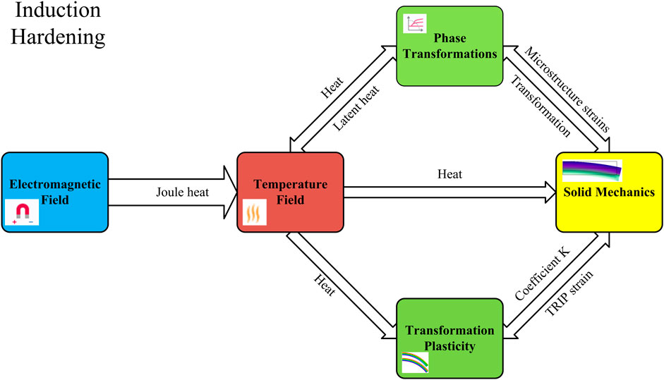
FIGURE 1. Multi-physics couplings.
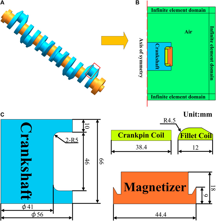
FIGURE 2. (A) Stepped shaft crankshaft; (B) IH model of axisymmetric crankshaft; (C) the detailed size of the model.
2.1 FEM model of electromagnetic-thermal part
2.1.1 Geometric model
Figure 2B illustrates the finite element model of induction heating of the crankshaft. The model comprises four regions: the crankshaft (blue), the induction coil (yellow), the magnetizer (orange), and the surrounding air (green). In order to meet the requirements of fillet quenching, arc coils are positioned at the fillet to maintain a stable air gap between the coil and the fillet. During operation, alternating current flows into one end of the induction coil and exits from the other end, generating an alternating magnetic field. The eddy currents induced by the magnetic field lines cause the surface of the crankshaft to heat up. In order to improve the heating efficiency and quality of the induction coil, a magnetizer is incorporated into the model to adjust the magnetic field distribution surrounding the induction coil. Additionally, to ensure accurate analysis and prevent the electromagnetic field from escaping into the surrounding air, a far-field model of the air is established during the induction heating process (Sun et al., 2022).
2.1.2 Material properties
The crankshaft is composed of 34CrNi3MoA alloy structural steel, as shown in Table 1. The density of the crankshaft is assumed to be constant at 7,800. The thermal conductivity, specific heat, resistivity, and relative permeability of the material properties change with temperature. To determine these properties during heating, JMatPro software was utilized, and the detailed information is presented in Table 2. For the heat transfer analysis, only the material properties relevant to the magnetic field of the magnetizer, induction coil, and air are considered, Both air and induction coils have a relative permeability of 1, while the relative permeability of the magnetizer is 600.

TABLE 1. The composition of 34CrNi3MoA (wt.%).
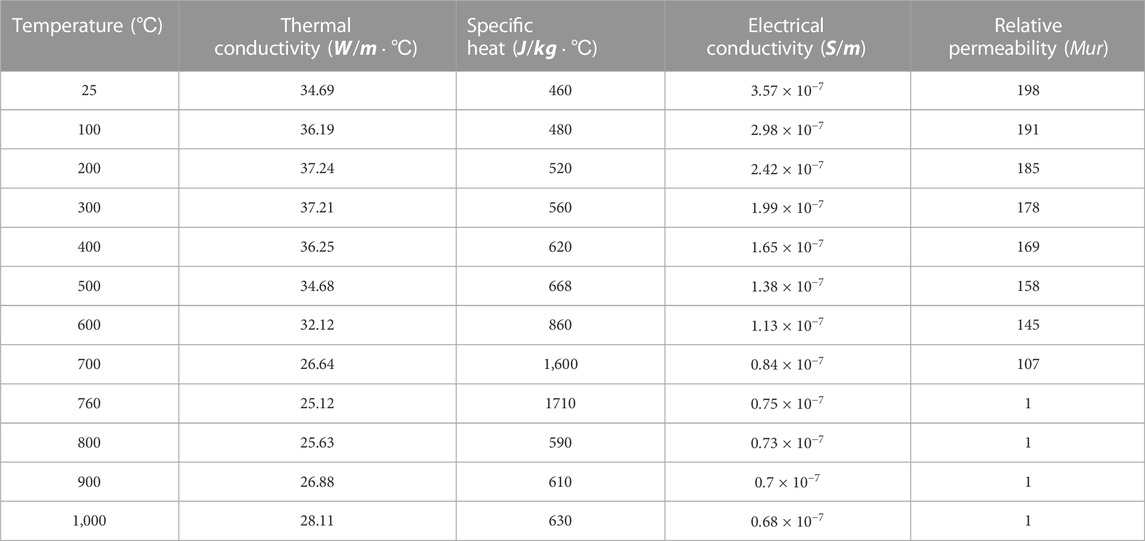
TABLE 2. Computed material properties of 34CrNi3MoA steel related to the temperature field. The calculation was performed using the JMatPro model (Mekky, (2020) verified the validity and applicability of the model.).
2.1.3 Meshing
The COMSOL Multiphysics finite element simulation software employs a free triangular mesh that is adaptively refined to enhance the model’s accuracy. Considering the skin effect, the electromagnetic field induces eddy currents primarily concentrated on the surface area. This leads to rapid heating and significant temperature changes on the crankshaft surface. To ensure precise calculations, a boundary layer mesh is applied to the crankshaft surface. The boundary layer is composed of 8 layers with a stretching factor of 1.2 and a thickness adjustment factor of 1. Additionally, to ensure accurate calculation of the electromagnetic field, the grid size of the induction coil is set to

FIGURE 3. The FEM mesh of electromagnetic-thermal part.
2.1.4 Boundary conditions and load
During the induction heating, both convection and radiation heat occur between the crankshaft surface and the surrounding air. The boundary conditions can be expressed as follows (Gao et al., 2014):
The convective heat transfer coefficient
In practical applications, the semi-annular inductor is commonly employed for crankshaft induction heating. One-ninth of the circumference is allocated to the induction coil used for heating the crankpin, while one-third of the circumference is allocated to the induction coil used for heating the fillet (Li, 2015). During the induction heating process, the crankshaft rotates at a constant speed around the induction coil, while its surface is heated uniformly. As a result, the equivalent heating period for the crankpin region is one-third of that for the fillet region. In this study, the crankpin heating mechanism is set to intermittent heating, with a heating duration of 0.5 s and a current termination period of 1 s. The load conditions are detailed in Table 3.
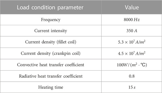
TABLE 3. Load and boundary conditions.
2.2 FEM model of thermal-microstructure-stress part
During the heating process, the surface temperature of the crankshaft rises, leading to the microstructure transformation into an austenite structure. As the temperature reaches the initial austenitizing temperature of
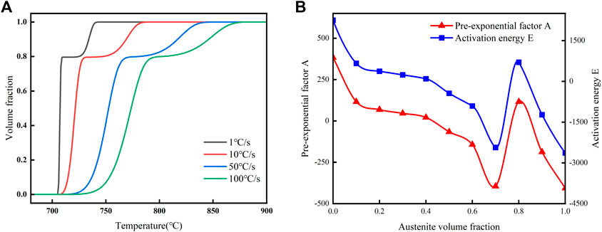
FIGURE 4. (A) Austenite transformation curves; (B) Functions of pre-exponential factor A and activation energy E related to austenite volume fraction in Eq. 5.
During continuous heating, the austenite change rate can be expressed as a derivative of temperature:
Substituting Eq. 4 into Eq. 3, the transformation model of austenitizing content and temperature can be obtained:
The derivative of the austenite content with respect to temperature can be determined using Figure 4A. By considering
To depict the phase transformation, microstructure, and hardness after quenching, the continuous cooling transformation (CCT) curve of 34CrNi3MoA steel is generated using JMatPro software, as illustrated in Figure 5A. When the microstructure is fully austenitized initially and the cooling rate exceeds
where,
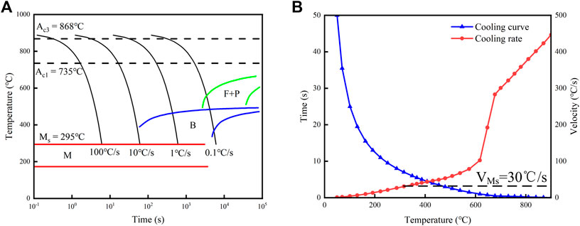
FIGURE 5. (A) The isothermal transformation diagram of 34CrNi3MoA steel; (B) Cooling characteristic curve.
The hardness of a material can be considered as a function of temperature and the distribution of its microstructure, given the known microstructure content. In accordance with the microhardness increment theory, the hardness can be formulated as follows:
The total strain is comprised of elastic strain, plastic strain, thermal strain, microstructure strain and transformation induced plastic strain during the induction hardening process. Therefore, the total strain tensor can be mathematically expressed as follows (Tong et al., 2018b):
where,
In order to calculate the total strain value in the induction quenching process, in this paper, JMatPro software is used to calculate the curves of Young's modulus, Poisson's ratio, thermal expansion coefficient, and TRIP coefficient with temperature, as shown in Figure 6. It can be seen that above the martensite starting temperature
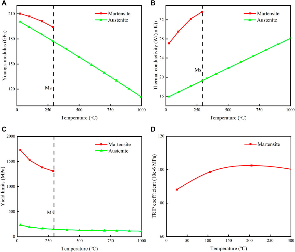
FIGURE 6. Computed material properties of 34CrNi3MoA steel. The calculation was performed using the JMatPro model. (Mekky, (2020) verified the validity and applicability of the model.): (A) Elastic modulus; (B) thermal coefficient; (C) yield limits; (D) the transformation plasticity coefficient.
3 Results and analyses
3.1 Temperature field
The induction hardening process consists of two main stages: electromagnetic induction heating and quenching cooling. The accurate modeling of the crankshaft’s temperature field during induction heating plays a crucial role in achieving desirable quenching quality. By observing the temperature field’s evolution over time and frequency, it becomes possible to achieve an optimal distribution of the hardened layer within the crankshaft.
3.1.1 The influence of current frequency on temperature field
Applying different frequencies of current to an induction coil yields varying distributions of magnetic induction intensity and temperature fields. Selecting the appropriate intermediate current frequency becomes crucial in achieving a more uniform temperature field. To investigate the influence of current frequency on the temperature field, we employ the control variable method, simulating induction heating by adjusting the current frequency based on the load parameters outlined in Table 3. Figure 7A illustrates the temperature field distribution along the center point A to the fillet point E of the crankshaft surface at different frequencies. As the frequency increases, the maximal temperature difference between the crankpin and the fillet decreases from
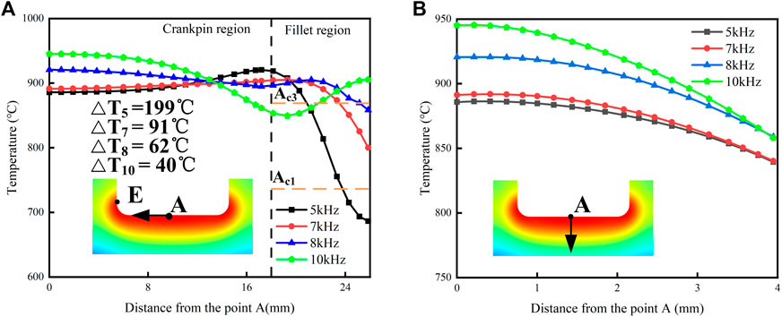
FIGURE 7. (A) Temperature distribution along the axial direction at different frequencies. The temperature difference (
3.1.2 The influence of heating time on the temperature field
In order to observe the magnetic field line and temperature field evolution of the crankshaft over time, we conducted an induction quenching experiment at an
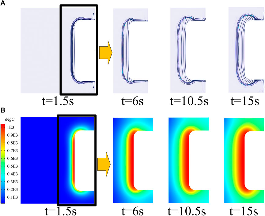
FIGURE 8. (A) Magnetic line evolutions during heating; (B) temperature evolutions during heating.
In order to provide a detailed temperature distribution of the crankshaft surface, Figure 9A illustrates the temperature field curve along the center point A to the fillet point E at different heating times. As the heating time increases, both the maximum temperature on the crankshaft surface and the temperature difference between the crankpin and the fillet decrease consistently. At a heating time of
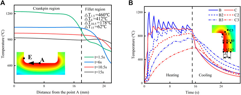
FIGURE 9. (A) Temperature distribution on the surface at different times. The temperature difference (
3.2 Microstructure field
After induction hardening of the crankshaft, a hardened layer is formed through martensitic transformation. This hardened layer can be divided into three regions: the hardened layer (
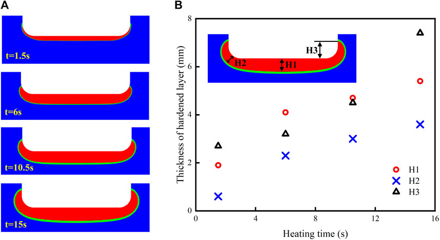
FIGURE 10. (A) Martensite content at different heating; (B) Hardened layer thickness at different heating.
3.3 Stress field
When the microstructure transitions from austenite to martensite during cooling process, due to the varied thermoplastic properties of the various phases illustrated in Figure 6, an uneven residual stress distribution is formed, as shown in Figure 11A. The crankshaft’s surface experiences tensile stress initially during cooling, while the interior experiences compressive stress. In the intermediate cooling phase, the surface layer reaches the
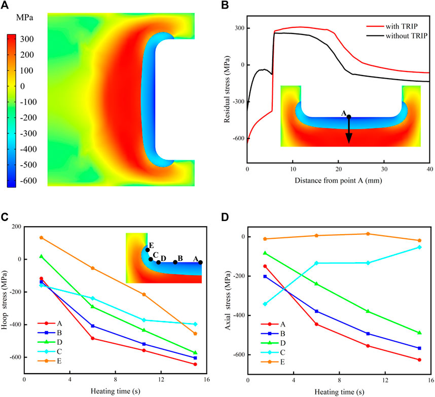
FIGURE 11. (A) Hoop stress field distribution after quenching; (B) simulated hoop stresses with and without TRIP strain; (C)hoop stress; (D) axial stress.
In order to analyze the influence of the TRIP effect on the induction quenching process, the numerical simulation of crankshaft induction quenching in the second section is repeated without the TRIP. Figure 11B illustrates the residual stress distribution along the radial orientation of the crankpin center with and without the TRIP effect. It is evident that the non-TRIP model exhibits approximately
The generation of residual stress is attributed to the combined effect of thermal stress and microstructure stress. Thermal stress is primarily influenced by the crankshaft structure and heat treatment technology, while microstructure stress is predominantly influenced by phase transformation in the hardened layer region. Figures 11C, D illustrate the distribution of hoop and axial residual stress on the crankshaft surface at different heating times. With increased heating time, the thickness of the hardened layer on the surface increases, leading to reduced constraint within the crankshaft’s hardened layer. Consequently, the axial and hoop stress at points A, B, and D in the crankpin region gradually decrease. The expansion constraint is one of the most significant means of producing residual tension, however, the expansion constraint of the crankarm on the fillet cannot be represented in the two-dimensional model. Figure 11D demonstrates a gradual decrease in axial stress and an increase in hoop stress at point C in the fillet area with increasing heating time. By adjusting the heating time, the value of residual stress after surface quenching can be modified while keeping other process parameters constant.
Figure 12 depicts the distribution of hoop and axial residual stress along the radial orientation of the crankpin center at varying thicknesses of the hardened layer. The hoop and axial stress patterns on the crankshaft exhibit similarities. With an increase in hardened layer thickness, the surface of the crankshaft experiences a progressively higher compressive residual stress. Additionally, the peak tensile stress on the crankshaft surface gradually shifts inward, effectively mitigating residual deformation. However, it is important to note that an excessively thick hardened layer can lead to the formation of coarse austenite grains, which may compromise the quenching performance of the workpiece. In this study, the austenitizing process is determined solely based on the temperature method, disregarding the uniformity and grain size of the austenite. Future research will focus on developing an austenitizing kinetic model and investigating the influence of austenite particle size.
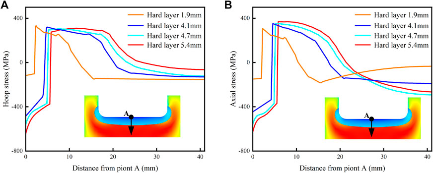
FIGURE 12. (A) Hoop stress at different hardened layer thickness; (B) axial stress at different hardened layer thickness.
4 Experimental validation
In order to verify the accuracy of the simulation results, a medium-frequency induction hardening experiment was conducted on an H-type specimen of 34CrNi3MoA steel. The induction hardening process parameters were set as follows: power of
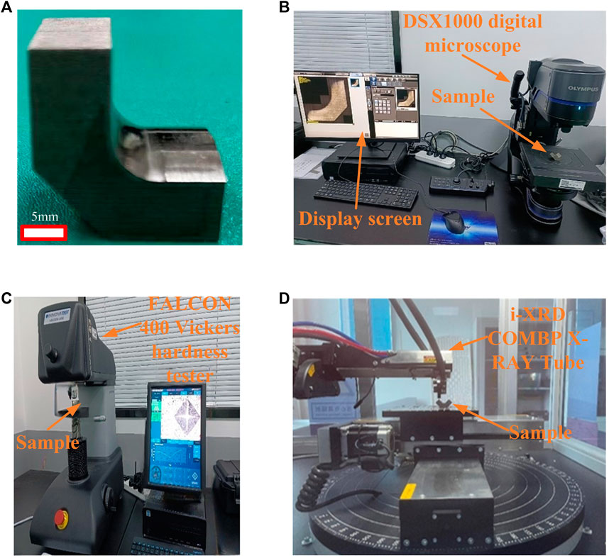
FIGURE 13. (A) Medium frequency hardening; (B) metallographic characterization; (C) residual stress detection; (D) hardness detection.
The comparison of experimental and simulated distributions of the hardened layer is presented in Figure 14A. The error between the fillet and crankpin areas is
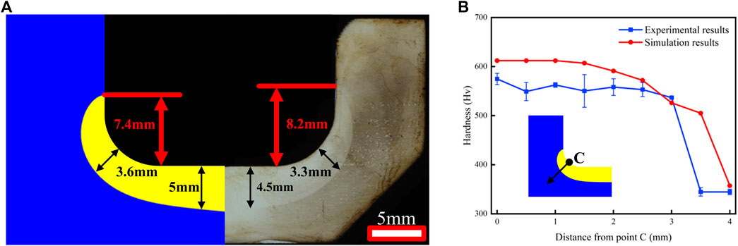
FIGURE 14. (A) Comparison of experimental and simulated hardened layer; (B) comparison of experimental and simulated hardness.
Table 4 presents the comparison between simulated and experimental residual stresses in the hoop and axial dimensions at the center point A of the crankpin surface and the center point C of the fillet surface. For the crankpin location, the axial and hoop errors between the simulation and test results are
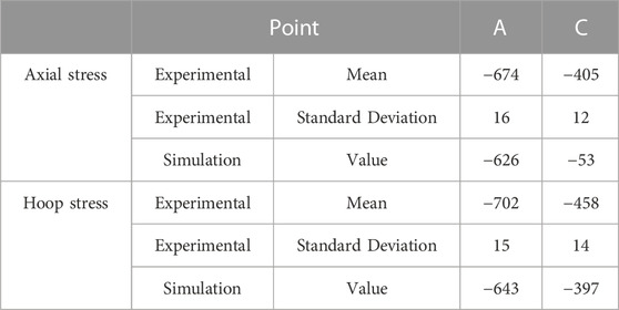
TABLE 4. The residual stress (mean and standard deviation) measured by the experiment was compared with the simulated residual stress. The positioning of the measurement points is determined by referencing Figure 11, where point A is situated at the midpoint of the crank pin surface, and point C is positioned at the midpoint of the fillet surface. All dimensions are in MPa.
5 Discussion
The results of numerical simulations and experimental validations presented in the preceding section have conclusively shown that medium-frequency induction hardening significantly alters the residual stress state on the surface of crankshafts. In all cases, both circumferential and axial residual tensile stresses on the crankshaft surface transform into compressive states after induction hardening. The degree of this transformation primarily depends on heating time and cooling rate.
Heating time plays a crucial role in determining the depth of the hardened layer. Longer heating times result in a larger region of the crankshaft surface reaching the Curie point, leading to a more extensive demagnetization zone. This, in turn, enhances heat conduction and increases the heated area, resulting in a thicker heat-treated layer on the crankshaft. During the quenching process, only a certain depth of the crankshaft surface undergoes a phase transformation, while the core structure remains unchanged. Therefore, longer heating times contribute to a more pronounced transformation into a compressive stress state. In general, the crankshaft exhibits a notable temperature gradient during induction heating or cooling, potentially causing deformation. Appropriately prolonging the heating time can foster a uniform distribution of surface temperature across the crankshaft.
Higher cooling rates lead to a more pronounced transformation into compressive stress. When the cooling rate exceeds a critical threshold, austenite undergoes a phase transformation, forming martensite in the hardened layer. The structural stress of martensite induce a stronger phase transformation effect and classical plasticity.
This holds significant importance for the practical application of surface hardening in crankshafts. Based on the Goodman theory and the linear relationship between residual stress and fatigue limits, the residual compressive stress generated on the crankshaft’s surface after strengthening can counteract the tensile stress experienced during operational conditions. Consequently, this can enhance the fatigue limit of the crankshaft.
Considering the change of residual stress from the surface to the core of the crankshaft with or without TRIP strain, since the induction quenching process only undergoes martensitic transformation on the surface layer and still maintains the original structure state inside, there is a significant difference in the residual stress between the two on the surface layer of the crankshaft. In comparison to experimental data obtained through X-ray diffraction techniques, numerical models that incorporate TRIP strain provide more accurate results. Hence, TRIP strain should be regarded as a crucial factor in the numerical modeling of induction hardening.
In these studies, we employed a simplified two-dimensional symmetric model that effectively simulated the residual stresses following induction hardening of crankshafts. However, we anticipate that the use of a more complex three-dimensional model will yield superior results. We assumed that the microstructure after induction heating comprises a uniform and entirely austenitic phase. In fact, the material may be anisotropic, it may also contain a smaller proportion of other microstructures (bainite and retained austenite) after quenching. This accounts for the relative error between surface hardness obtained in experiments and the results derived from numerical simulations. These aspects will be addressed and resolved in our future work.
6 Conclusion
The evolution of temperature field, microstructure field, and residual stress field in a marine diesel engine crankshaft made of 34CrNi3MoA steel during medium-frequency induction hardening was studied. Our study employed an electromagnetic-thermal-transformation-stress/strain coupled numerical model that accounted for the influence of internal stress induced by TRIP on residual stress. The following conclusions can be drawn.
1) As the frequency of the current increases, the temperature difference on the crankshaft surface decreases. However, excessively low frequencies result in inadequate heating of the fillet region, while excessively high frequencies lead to significant temperature disparities between the adjacent fillet area and the crankpin. By setting the heating frequency to
2) Increasing the heating time enlarges the demagnetization region on the crankshaft surface, causing the dense area of magnetic lines to gradually shift towards the interior. Simultaneously, the surface heating temperature decreases, resulting in improved temperature uniformity across the crankshaft surface. After heating for
3) The transformation plasticity during induction hardening has a notable impact on the distribution of residual stress in the crankshaft. The non-TRIP model exhibits a surface residual compressive stress
4) In line with the theoretical analysis of induction quenching residual stress, the crankshaft exhibits compressive residual stress on the surface, tensile stress in the subsurface, and compressive stress at the center.
5) The surface of the crankshaft exhibits increasing residual compressive stress as the thickness of the hardened layer increases. Simultaneously, the peak tensile stress on the surface of the crankshaft gradually shifts inward, effectively preventing residual deformation. Modifying the thickness of the hardened layer allows for adjustment of the residual stress value after quenching, ensuring compliance with design specifications.
To conclude, studying the distribution of residual stress after induction quenching of a crankshaft is crucial for enhancing its fatigue life. This paper successfully investigates the impact of induction quenching process parameters on the quenching performance of a 34CrNi3MoA steel crankshaft, offering valuable insights for process optimization. Moreover, the proposed numerical model for crankshaft induction quenching, which considers the influence of TRIP, demonstrates excellent agreement with experimental findings, validating its accuracy and reliability.
Data availability statement
The original contributions presented in the study are included in the article/Supplementary Material, further inquiries can be directed to the corresponding author.
Author contributions
JC, experimental method design. KW and JT, data collection and collation. CL, original Draft. XS, review and revision. GL, administrative and technical support. All authors contributed to the article and approved the submitted version.
Funding
This study was supported by the National Natural Science Foundation of China (Grant No. 62203193), General project of natural science research of Institutions of Higher Education of Jiangsu Province of China (Grant No. 21KJB510016).
Conflict of interest
The authors declare that the research was conducted in the absence of any commercial or financial relationships that could be construed as a potential conflict of interest.
Publisher’s note
All claims expressed in this article are solely those of the authors and do not necessarily represent those of their affiliated organizations, or those of the publisher, the editors and the reviewers. Any product that may be evaluated in this article, or claim that may be made by its manufacturer, is not guaranteed or endorsed by the publisher.
References
Areitioaurtena, M., Segurajauregi, U., Fisk, M., Cabello, M. J., and Ukar, E. (2022). Numerical and experimental investigation of residual stresses during the induction hardening of 42CrMo4 steel. Eur. J. Mech. - A/Solids 96, 104766. doi:10.1016/j.euromechsol.2022.104766
Barglik, J., Smalcerz, A., Przylucki, R., and Doležel, I. (2014). 3D modeling of induction hardening of gear wheels. J. Comput. Appl. Math. 270, 231–240. doi:10.1016/j.cam.2014.01.019
Coupard, D., Palin-luc, T., Bristiel, P., Ji, V., and Dumas, C. (2007). Residual stresses in surface induction hardening of steels: comparison between experiment and simulation. Mater. Sci. Eng. A 487 (1), 328–339. doi:10.1016/j.msea.2007.10.047
Gao, K., and Qin, X. (2020). Effect of feed path on the spot continual induction hardening for different curved surfaces of AISI 1045 steel. Int. Commun. Heat Mass Transf. 115 (C), 104632. doi:10.1016/j.icheatmasstransfer.2020.104632
Gao, K., Qin, X., Wang, Z., Chen, H., Zhu, S., Liu, Y., et al. (2014). Numerical and experimental analysis of 3D spot induction hardening of AISI 1045 steel. J. Mater. Process. Technol. 214 (11), 2425–2433. doi:10.1016/j.jmatprotec.2014.05.010
Gao, K., Qin, X., Wang, Z., and Zhu, S. (2016). Effect of spot continual induction hardening on the microstructure of steels: comparison between AISI 1045 and 5140 steels. Mater. Sci. Eng. A 651, 535–547. doi:10.1016/j.msea.2015.11.012
Jang, J.-Y., and Chiu, Y.-W. (2007). Numerical and experimental thermal analysis for a metallic hollow cylinder subjected to step-wise electro-magnetic induction heating. Appl. Therm. Eng. 27 (11-12), 1883–1894. doi:10.1016/j.applthermaleng.2006.12.025
Jian, S., Wang, J., Xu, D., Ma, R., Huang, C., Lei, M., et al. (2022). Gradient microstructure and mechanical properties of Ti-6Al-4V titanium alloy fabricated by high-frequency induction quenchingtreatment. Mater. Des. 222, 111031. doi:10.1016/j.matdes.2022.111031
Kaiser, D., Damon, J., Mühl, F. B., de Graaff, B., Kiefer, D., Dietrich, S., et al. (2020). Experimental investigation and finite-element modeling of the short-time induction quench-and-temper process of AISI 4140. J. Mater. Process. Tech 279, 116485. doi:10.1016/j.jmatprotec.2019.116485
Li, H., He, L., Gai, K., Jiang, R., Zhang, C., and Li, M. (2015). Numerical simulation and experimental investigation on the induction hardening of a ball screw. Mater. Des. 87, 863–876. doi:10.1016/j.matdes.2015.08.094
Li, J. (2015). Numerical studies on the induction quenching process of crankshaft. Beijing, China: Beijing Institute of Technology.
Liu, Y., Yang, Z., Zhai, Z., Zhao, C., and Zhai, T. (2019). Optimization of induction quenching processes for HSS roll based on MMPT model. Metals 9 (6), 663. doi:10.3390/met9060663
Maialen, A., Unai, S., Martin, F., Eneko, U., and Ukar, E. (2022). Influence of induction hardening residual stresses on rolling contact fatigue lifetime. Int. J. Fatigue 159, 106781. doi:10.1016/j.ijfatigue.2022.106781
Mekky, A. B. H. (2020). Computational modelling for specific heat and thermal conductivity of austenitic stainless steels alloys at solid phase. Revue Des Compos. Des Materiaux Avances, Int. Inf. Eng. Technol. Assoc. 30 (1), 23–27. doi:10.18280/rcma.300104
Montalvo-Urquizo, J., Liu, Q., and Schmidt, A. (2013). Simulation of quenching involved in induction hardening including mechanical effects. Comput. Mater. Sci. 79, 639–649. doi:10.1016/j.commatsci.2013.06.058
Pokorný, P., Dlhý, J., Poduška, R., Fajkoš, T., Vojtek, L., Náhlík, M., et al. (2020). Influence of heat treatment-induced residual stress on residual fatigue life of railway axles. Theor. Appl. Fract. Mech. 109, 102732. doi:10.1016/j.tafmec.2020.102732
Prisco, U. (2018). Case microstructure in induction surface hardening of steels: an overview. Int. J. Adv. Manuf. Technol. 98 (9-12), 2619–2637. doi:10.1007/s00170-018-2412-0
Qin, W. J., Dong, C., and Li, X. (2016). Assessment of bending fatigue strength of crankshaft sections with consideration of quenching residual stress. J. Mater. Eng. Perform. 25 (3), 938–947. doi:10.1007/s11665-016-1890-1
Rohde, J., and Jeppsson, A. (2000). Literature review of heat treatment simulations with respect to phase transformation, residual stresses and distortion. Scand. J. Metallurgy 29 (2), 47–62. doi:10.1034/j.1600-0692.2000.d01-6.x
Rudnev, V. I., and Loveless, D. (2014). “Induction hardening,” in Comprehensive materials processing, 489–580.
Santhanakrishnan, S., and Kovacevic, R. (2012). Hardness prediction in multi-pass direct diode laser heat treatment by on-line surface temperature monitoring. J. Mater. Process. Technol. 212 (11), 2261–2271. doi:10.1016/j.jmatprotec.2012.06.002
SongSong, S., Xingzhe, Z., Chang, W., Maosong, W., and Fengkui, Z. (2021). Crankshaft high cycle bending fatigue research based on the simulation of electromagnetic induction quenching and the mean stress effect. Eng. Fail. Anal. 122, 105214. doi:10.1016/j.engfailanal.2021.105214
Sun, S., Zhang, X., Wan, M., Gong, X., and Xu, X. (2022). Study of quenched crankshaft high-cycle bending fatigue based on a local sub model and the theory of multi-axial fatigue. Metals 12 (6), 913. doi:10.3390/met12060913
Tian, J., Tong, J., and Luo, S. (2018). Differential steering control of four-wheel independent-drive electric vehicles. Energies 11 (11), 2892. doi:10.3390/en11112892
Tian, J., Wang, Q., Ding, J., Wang, Y., and Ma, Z. (2019). Integrated control with DYC and DSS for 4WID electric vehicles. IEEE Access 7, 124077–124086. doi:10.1109/access.2019.2937904
Tong, D., Gu, J., and Totten, G. E. (2018a). Numerical investigation of asynchronous dual-frequency induction hardening of spur gear. Int. J. Mech. Sci. 142-143, 1–9. doi:10.1016/j.ijmecsci.2018.04.036
Tong, D., Gu, J., and Totten, G. E. (2017). Numerical simulation of induction hardening of a cylindrical part based on multi-physics coupling. Model. Simul. Mater. Sci. Eng. 25 (3), 035009. doi:10.1088/1361-651x/aa5f7c
Tong, D., Gu, J., and Yang, F. (2018b). Numerical simulation on induction heat treatment process of a shaft part: involving induction hardening and tempering. J. Mater. Process. Technol. 262, 277–289. doi:10.1016/j.jmatprotec.2018.06.043
Umberto, P. (2018). Case microstructure in induction surface hardening of steels: an overview. Int. J. Adv. Manuf. Technol. 98 (9-12), 2619–2637. doi:10.1007/s00170-018-2412-0
Wang, X., Meng, Q., Wang, Z., Gan, J., Yang, Y., Qin, X., et al. (2019). Prediction of the surface characteristic of 42CrMo after spot continual induction hardening based on a novel co-simulation method. Surf. Coatings Technol. 357, 252–266. doi:10.1016/j.surfcoat.2018.09.088
Wu, C., and Sun, S. (2021). Crankshaft high cycle bending fatigue research based on a 2D simplified model and different mean stress models. J. Fail. Analysis Prev. 21 (4), 1396–1402. doi:10.1007/s11668-021-01192-w
Zhong, H., Wang, Z., Gan, J., Wang, X., Yang, Y., He, J., et al. (2020). Numerical simulation of martensitic transformation plasticity of 42CrMo steel based on spot continual induction hardening model. Surf. Coatings Technol. 385 (C), 125428. doi:10.1016/j.surfcoat.2020.125428
Zhu, S., Wang, Z., Qin, X., Mao, H., and Gao, K. (2015). Prediction of phase transformation and hardness distribution of AISI 1045 steel after spot continual induction hardening. J. Mater. Eng. Perform. 24 (10), 3919–3932. doi:10.1007/s11665-015-1680-1
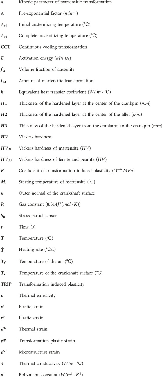
Nomenclature
Keywords: induction quenching, 34CrNi3MoA steel, temperature field, microstructure field, hardened layer, residual stress
Citation: Shi X, Lv C, Li G, Wang K, Chen J and Tang J (2023) Study on induction hardening performance of 34CrNi3MoA steel crankshaft. Front. Mater. 10:1240087. doi: 10.3389/fmats.2023.1240087
Received: 14 June 2023; Accepted: 19 September 2023;
Published: 29 September 2023.
Edited by:
Francesco Ascione, University of Salerno, ItalyReviewed by:
Wojciech Macek, Gdansk University of Technology, PolandVincent Ji, Université Paris-Saclay, France
Copyright © 2023 Shi, Lv, Li, Wang, Chen and Tang. This is an open-access article distributed under the terms of the Creative Commons Attribution License (CC BY). The use, distribution or reproduction in other forums is permitted, provided the original author(s) and the copyright owner(s) are credited and that the original publication in this journal is cited, in accordance with accepted academic practice. No use, distribution or reproduction is permitted which does not comply with these terms.
*Correspondence: Guochao Li, bGlndW9jaGFvQGp1c3QuZWR1LmNu