 Yifei Zhang1
 Zhimei Jiang
- 1Anhui Provincial Highway Engineering Testing Center, Anhui, China
- 2State Key Laboratory of Mountain Bridge and Tunnel Engineering, Chongqing Jiaotong University, Chongqing, China
- 3School of Civil Engineering, Chongqing Jiaotong University, Chongqing, China
Ultra-high performance concrete (UHPC) is a new class of structural material with outstanding properties of high strength, excellent ductility, and durability, which has an extremely broad application field. To examine the rehabilitation potential of UHPC on the existing masonry structures, the mechanical behavior of square masonry columns strengthened with UHPC under eccentric loading was investigated in this paper. A total of six masonry columns with or without the confinement of UHPC jackets were axially and eccentrically loaded. The strengthening effectiveness of UHPC on masonry columns was explored in terms of failure mode, deformation capacity, and carrying capacity. The results showed that UHPC jacketing is a highly effective technique for strengthening masonry columns, significantly increasing both the load-carrying capacity and transverse deformability of eccentrically compressed masonry columns (up to 103.64% and 71.43%, respectively). Furthermore, the UHPC strengthening technique modified brittle damage in unconfined masonry columns. A theoretical calculation was carried out for determining the bearing capacity of masonry columns strengthened with UHPC under eccentric loading. The accuracy of the theoretical calculation method was verified by comparing the theoretical values with the experimental values. Thus, this study provides a theoretical basis for the practical application of masonry structures strengthened with UHPC.
1 Introduction
The masonry structure is one of the oldest forms of building structure. Few examples are the Great Wall of China, the Imperial Palace, the Egyptian pyramids, and the Zhaozhou Bridge (selected by the American Society of Civil Engineers as a milestone in civil engineering) (Yang and Cheng, 2013; Wang et al., 2020). It has been a remarkable achievement during the evolution of human society. In recent decades, strengthening of the most existing masonry structures has become challenging owing to the degradation of masonry materials and functional changes of masonry structures, whilst masonry removal and reconstitution are time-consuming and expensive (Fayala et al., 2016; Li et al., 2021). Conventional methods used for strengthening masonry columns can be divided into direct strengthening methods (i.e., mesh reinforcement, mortar joint treatment, and surface treatment) and indirect strengthening methods (post-tension and external steel reinforcement) (Wang et al., 2018). Nevertheless, numerous shortcomings were observed for traditional strengthening methods, including increased weight, low durability of structures and impact on the sizes, and the appearance of original structures. In particular, the fiber-reinforced polymer (FRP) is the most commonly used strengthening material for masonry columns to enhance the axial compression and deformation capacity (Vincent and Ozbakkaloglu, 2013; Witzany et al., 2014; Babatunde, 2017; Alotaibi and Galal, 2018). It has been confirmed (through numerous investigations) that FRP, with its advantages of light weight, high strength, good corrosion resistance, and design capability, has the ability to replace most traditional strengthening methods (Corradi et al., 2007; Alotaibi and Galal, 2018). However, the combination with an organic matrix (epoxy resin) is needed for FRP applications, which leads to several weaknesses being exhibited in FRP, including poor fire resistance, stringent external environmental requirements at the interface between old and new structures, and poor permeability (Cevallos et al., 2015; Ombres and Verre, 2015; Deng and Li, 2020; Wan et al., 2021). In addition, FRP, which has brittle damage characteristics, exhibits poor ductility under load (Zou et al., 2023a). Thus, an effective strengthening material or strengthening method for repairing masonry columns is urgently needed. The shortcomings of FRP-strengthened masonry columns can be compensated by using ultra-high performance concrete (UHPC) (Zhang et al., 2023).
UHPC is a new class of cementitious composite material proposed by de Larrard and Sedran (1994). Its compressive strength was demonstrated to be more than 150 MPa. Moreover, the fracture energy and Young’s modulus were within the range of 1,200–40,000 J/m2 and 50–60 MPa, respectively. It achieved a major span in the performance of engineering materials (Richard and Cheyrezy, 1994; Richard and Cheyrezy, 1995; AFGC-SETRA, 2002; Schmidt and Fehling, 2005; Yazıcı et al., 2009). Compared to normal concrete (NC), UHPC has significant advantages in terms of corrosion resistance, toughness, and impermeability (Guan et al., 2022). Meanwhile, owing to the high density and compactness of UHPC materials, superior mechanical and physical performance can prevent the ingress of dangerous substances, resulting in enhanced durability of structures (Lee et al., 2007; Yang et al., 2022; Yang et al., 2023). Furthermore, UHPC is characterized with an excellent self-healing ability (Beglarigale et al., 2021). Therefore, UHPC has been broadly adopted in practical engineering applications, such as high-rise buildings, structural rehabilitation, and large-span bridges (Azmee and Shafiq, 2018; Haber et al., 2018; Zhou et al., 2018; Zou et al., 2023b). The strengthening effectiveness of UHPC layers on masonry walls under horizontal cyclic force and continuous axial compression was investigated by Peng et al. (2019). The results indicated that the in-plane shear resistance and cracking load of masonry walls can be enhanced to 193% and 127%, respectively, by UHPC. Wang et al., 2022 applied UHPC to repair damaged stone arch bridges. The results discovered that the stiffness and bearing capacity of strengthened structures were significantly improved and pointed to the reliability of application in stone arch bridges with UHPC. To determine the shear strength of the interface between UHPC and unreinforced masonry (URM) structures, an experimental study and finite element analysis were carried out by Lampropoulos et al. (2017). It was demonstrated that UHPC was extremely effective in enhancing the stiffness and strength of URM structures. Experimental parameters including grade of masonry mortar, method of strengthening, and thickness of strengthening were (Chen, 2021) considered during compressive tests of UHPC-strengthened masonry columns. The results revealed that the strength of masonry mortar was an essential factor influencing the compressive load-bearing capacity of structures. Under two-sided strengthening, the cracking loads were increased by 95%, 65.6%, and 270% and ultimate loads were increased by 58.7%, 82.7%, and 196.6%, respectively, with mortar strengths of M1, M2.5, and M5.
In conclusion, current research studies indicated that the strengthening of masonry structures using UHPC was effective, especially in terms of enhancing strength and stiffness. In theory, UHPC-strengthened masonry columns are expected to shine brightly in terms of the whole life cycle, durability, and low-carbonization. Nevertheless, the influence of eccentric loading on UHPC-strengthened structures was poorly recorded. There is a lack of experimental investigation and theoretical predictions for masonry columns strengthened with UHPC under eccentric loading. Therefore, the objective of this paper is to investigate the compressive performance of masonry columns strengthened with UHPC jackets under eccentric loads. Six columns, including four masonry columns without UHPC strengthening and two masonry columns strengthened with UHPC, were subjected to eccentric loading experiments, considering the influence of loading eccentricity. The compressive performance of masonry columns strengthened with UHPC was analyzed in terms of failure mode, peak load, load–displacement curves, and load–strain curves. Based on the calculation method of the normal section capacity of composite structures, a theoretical prediction method for determining load-carrying capacity was suggested for eccentrically compressed masonry columns strengthened with UHPC jackets.
2 Experimental program
2.1 Mechanical properties of the materials
In this study, the mechanical properties of stone, mortar, and UHPC were determined using standard tests.
2.1.1 Stone
All stones used in the paper were sandstones collected from Chongqing, China. The major mineral types in the sandstones were albite and quartz. In addition, they also consisted of illite, chlorite, and mica. To evaluate the compressive strength of stones, 12 specimens, with a dimension of 70 mm × 70 mm × 70 mm, were made according to the test methods of rock for highway engineering (JTG E41-2005) (JTG E41-2005, 2005), as shown in Figure 1. The average compression strength was 128.6 MPa, and the same batch of stone was used for the material and formal tests.
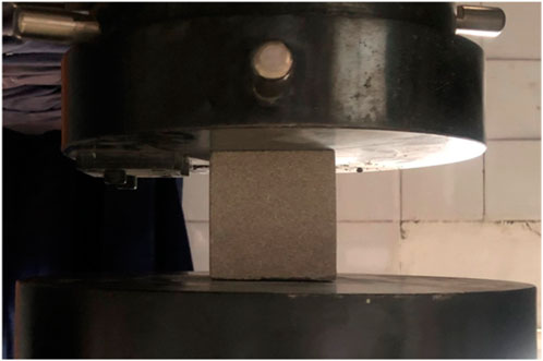
FIGURE 1. Testing of mechanical properties of stone.
2.1.2 Mortar
A cement mortar (with a cement: sand: water ratio of 1: 6.3: 1.17 by weight) was applied as a binder to construct the masonry columns. To determine the compressive strength of the mortar, the uniaxial compression test was carried out on six cubic specimens with a dimension of 70.7 mm × 70.7 mm × 70.7 mm as per the code for design of highway masonry bridges and culverts (JTG D61-2005) (JTG D61-2005, 2005). The test results of specimens are listed in Table 1, which shows that the average 28-day compressive strength of the mortar was 7.1 MPa under room temperature.

TABLE 1. Results of the mortar compressive test.
2.1.3 UHPC
Mix proportions of UHPC are shown in Table 2. Steel micro-fibers, i.e., copper-plated steel fibers were used at 2% volume fractions, with a diameter of 0.2 mm and a length of 12 mm. The basic material properties of UHPC are reflected in the mechanical tests. The compressive strength, elastic modulus, and tensile strength of UHPC were carried out at the ages of 1, 3, 7, 14, and 28 days. According to the reactive powder concrete (GB/T 31,387-2015) (GB/T 31387-2015, 2015), five cubic and five prismatic specimens of sizes 100 mm × 100 mm × 100 mm and 100 mm × 100 mm × 300 mm were prepared for testing the compressive strength and elastic modulus of UHPC, respectively. In order to determine the tensile strength of UHPC, five dog-bone specimens were constructed in accordance with the fundamental characteristics and test methods of UHPC (T/CBMF 37-2018) (T/CBMF 37-2018, 2018). The mechanical properties of UHPC are summarized in Table 3.
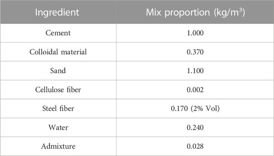
TABLE 2. Mixture design for the preparation of UHPC.
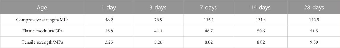
TABLE 3. Mechanical properties of UHPC at various ages.
2.2 Characteristics of column specimens
The strengthening details for the six columns are shown in Figure 2 and summarized in Table 3. For the nomenclature displayed in Table 4, U indicates unstrengthened, S indicates strengthened, E indicates eccentricity, the first subscript is strengthening thickness, and the second subscript is loading eccentricity. For example, “S-UHPC30-E30” represents masonry columns with a 30 mm UHPC strengthening layer subjected to 30 mm eccentric loading.
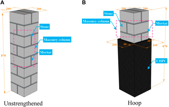
FIGURE 2. Strengthening details of the specimen (unit: mm). (A) Unstrengthened. (B) Hoop.
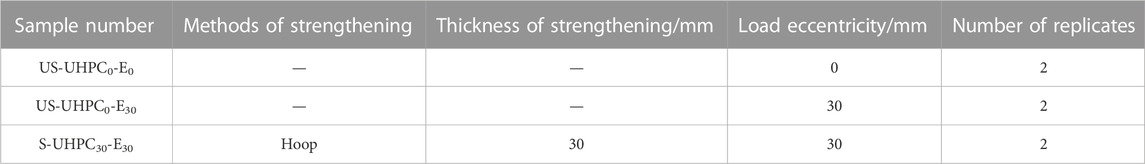
TABLE 4. Details of test specimens.
All of the masonry columns had a 200 × 200 mm2 cross section and a height of 870 mm, composed of eight rows of two stones (200 × 95 × 100 mm3). All stones were connected by mortar joints with an average thickness of 10 mm. Additionally, in order to avoid structural deformation, the vertical joints of adjacent layers were positioned in separate locations. After all unstrengthened columns had been cured at room temperature for 14 days, the strengthening of UHPC jackets was carried out according to the following steps: (a) a wooden formwork was prepared for the columns strengthened with UHPC and fixed; (b) the UHPC layer was poured and cured for 7 days; and (c) the wooden formwork was removed. The process of fabricating the experimental columns is shown in Figure 3.
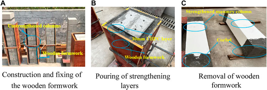
FIGURE 3. Preparation of experimental columns. (A) Construction and fixing of the wooden formwork. (B) Pouring of strengthening layers. (C) Removal of the wooden formwork.
2.3 Test procedure and instrumentations
In this experiment, the positive surface of the load was defined as the A surface, and the B, C, and D surfaces in clockwise order.
The schematic test setups for unstrengthened and strengthened columns are displayed in Figures 4A,B, respectively. The compression tests were conducted on the specimens using hydraulic jacks of 2000 kN grade. In addition, the central line was marked on the specimen beforehand, thus aligning the center of the tooling with the loading point. To confirm the proper functioning of the whole test system, the specimens were pre-loaded with 20 kN before formal loading. Then, the experimental columns were subjected to compression testing until failure by a displacement control at a rate of 0.1 mm/min.
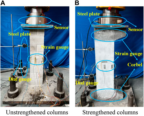
FIGURE 4. Test setup and instrumentation of the compressive test. (A) Unstrengthened columns. (B) Strengthened columns.
Two dial gauges were placed, respectively, at 3/8 H and 6/8 H of the B surface to record the transverse displacements. One dial gauge was placed at the middle height on the C surface to measure the vertical displacement. Strain gauges were mounted at the middle height on the A, B, and D surfaces of the columns to measure transverse and vertical strains. The arrangement is shown in Figure 5.
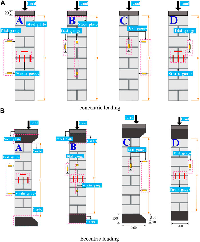
FIGURE 5. Arrangement of dial and strain gauges (unit: mm). (A) Concentric loading. (B) Eccentric loading.
3 Results and discussion
3.1 US-UHPC0-E0 group
3.1.1 Failure mode
The failure mode of group US-UHPC0-E0 specimens is shown in Figure 6. It can be seen that the cracks extended along the block from the middle to the ends when the specimens were destroyed. Meanwhile, the failure of specimens started after the crack penetrated, and the block lost its bearing capacity and collapsed. For US-UHPC0-E0-1, when the load was increased to 56% Pu, the crack was observed in the middle of the stones. With the further increase in load, the mortar joints were slagged but not cracked under compression. As the load was increased to 78% Pu, the cracks in the middle of the stones continued to extend and expand toward the ends. However, the cracks did not extend completely along the mortar layer. In addition, tiny cracks were found in other parts of the stone. A visible vertical through crack was noticeable in the middle of the specimen at failure, and, subsequently, the masonry column was broken into two parts and destroyed. The failure process of specimen US-UHPC0-E0-2 was approximately similar to US-UHPC0-E0-1. Owing to the short damage process of the specimen, the failure behavior of masonry columns was not thoroughly recorded (the damage mode had certain features of brittle damage). Overall, the failure mode of unstrengthened columns was the crushing failure of mid-masonry.
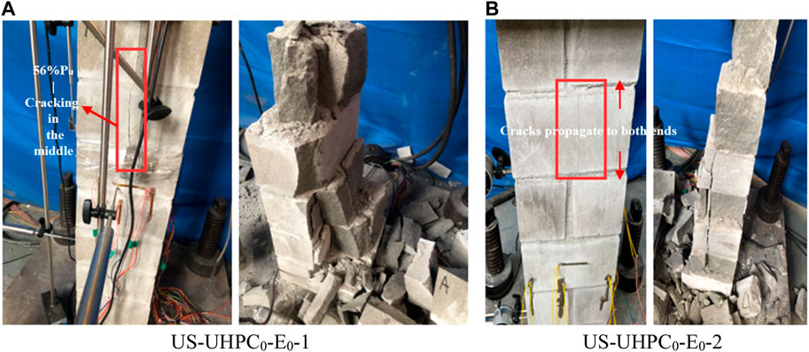
FIGURE 6. Failure modes of specimens. (A) US-UHPC0-E0-1. (B) US-UHPC0-E0-2.
3.1.2 Load–displacement behavior
The load–displacement curve of the axially loaded unstrengthened column is depicted in Figure 7. The mechanical properties of the control specimens (i.e., US-UHPC0-E0 group) were very weak, with poor stiffness and deformability. For US-UHPC0-E0-1, transverse and vertical displacements rapidly increased when the load was above 120 kN, corresponding to the mortar joints dropping slag during the test. With the further increase in load to 450 kN, the displacement sharply increased at this moment owing to the spalling of stones caused by the expansion of masonry cracks. Following the peak load, the sudden drop in load-carrying capacity of the specimen can be seen, exhibiting obvious brittle failure of the unstrengthened masonry column. For US-UHPC0-E0-2, the construction technique of masonry was better, and the structure as a whole was deformed in a coordinated way. Its displacement increased steadily with the increase in load, and the phenomenon of stone and masonry debonding was not observed during the experiment. Therefore, the bearing capacity of US-UHPC0-E0-2 was also superior. It is noteworthy that the ultimate loads of specimens were highly variable. The ultimate loads of specimens US-UHPC0-E0-1 and US-UHPC0-E0-2 were 581.47 kN and 797.58 kN, respectively. It can be attributed to the differences in construction techniques of masonry structures and damage differences caused during handling.
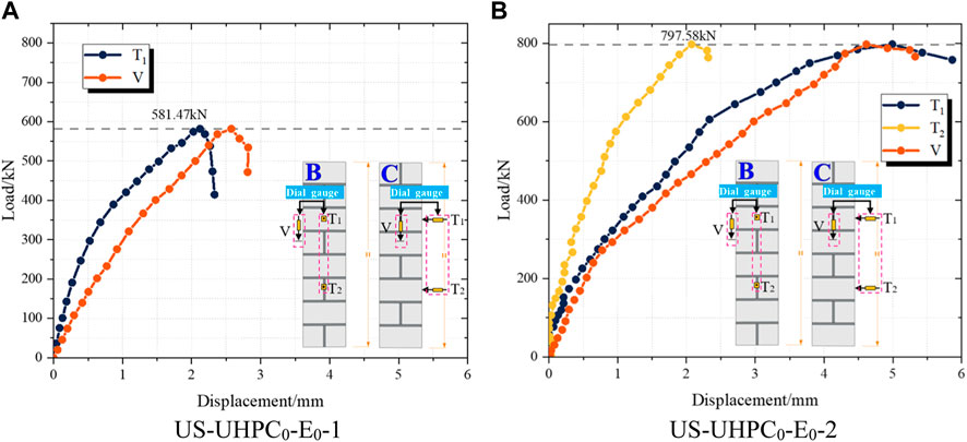
FIGURE 7. Load–displacement curves. (A) US-UHPC0-E0-1. (B) US-UHPC0-E0-2.
3.2 US-UHPC0-E30 group
3.2.1 Failure mode
Damage to unstrengthened columns under 30 mm eccentric loading is shown in Figure 8. No significant phenomena were observed in the specimens when the load was low. For US-UHPC0-E30-1, the masonry joints were observed to be debonded when the load was 60% Pu. As the load was further increased to 80% Pu, a number of stones were broken and slagged, and minor cracks appeared in stones on the A, C, and D surfaces. With the further increase in load, the cracks in the stones on the C and D surfaces approached penetration. The cracks were penetrated when the ultimate load was reached, and the specimen collapsed due to the loss of load-bearing capacity. For US-UHPC0-E30-2, the phenomena of specimen during the experiment were approximately similar to US-UHPC0-E30-1. When the specimen was destroyed, part of the masonry joints near the D surface had been peeled off under pressure, but it was not completely dehollowed. Meanwhile, the main crack was also observed on the D surface. With the increase in the load, the main cracks expanded to the A and C surfaces, while only some stones on the B surface displayed minor cracks. It is worth noting that the cracks on the C surface were more widely expanded when US-UHPC0-E30-1 was destroyed. Meanwhile, the blocks were also crushed. In contrast, when US-UHPC0-E30-2 was destroyed, there were only a few minor cracks on the C surface and the cracks were not penetrated. In general, the failure mode of specimens in group US-UHPC0-E30 was mainly crushing damage to masonry near the D surface.
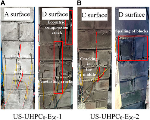
FIGURE 8. Failure modes of specimens. (A) US-UHPC0-E30-1. (B) US-UHPC0-E30-2.
3.2.2 Load–displacement behavior
The load–displacement curve of the eccentrically loaded unstrengthened masonry column is shown in Figure 9. The data on S-UHPC0-E30-2 were lost due to the accidental damage to equipment. The T1, T2, and V displacements of specimen S-UHPC0-E30-1 corresponding to the peak load were 3.7, 2.18, and 3.22 mm, respectively. The variation in displacement of specimen S-UHPC0-E30-1 at T1 and T2 was consistent with its damage mode. The displacement T1 was more than T2, and the slope of the load–displacement curve was greater. This was consistent with the upper part of UHPC0-E30-1 inclined during the actual eccentric loading. The displacement V was low, which can be analyzed by the damage mode of the C surface in Figure 8. The damage on the C surface was mainly observed on the top of V, while only a few minor cracks were observed on V and its lower part. Meanwhile, the masonry joints were not detached such that the values measured by V were small.
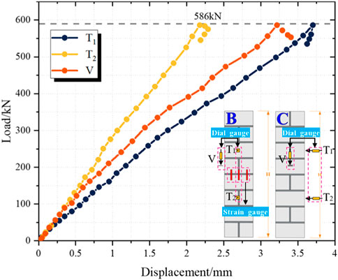
FIGURE 9. Load–displacement curve.
3.3 S-UHPC30-E30 group
3.3.1 Failure mode
The failure mode of the strengthened masonry column is shown in Figure 10. For S-UHPC30-E30-1, when the load reached 56% Pu, the sound of steel fibers being pulled off was observed. This observation demonstrated that UHPC was participating in the common loading of masonry columns. With the further increase in the eccentric load, the top of A, C, and D surfaces were all subjected to vertical cracks. When the load was increased to 82% Pu, the UHPC strengthening layer separated gradually from masonry forming cracks on the C surface, and UHPC peeling was observed on the A surface. Horizontal cracks appeared on the A and B surfaces when the specimens were loaded to 94% Pu. Eventually, with a loud noise, the UHPC strengthening layer was destroyed and the specimen failed. For S-UHPC30-E30-2, the sound of steel fibers being pulled off was noted when the specimen was loaded up to 59% Pu. As the load was increased to 79% Pu, vertical cracks appeared on the top of the D surface. When the load was further increased, the top of the C surface was cracked and the UHPC strengthening layer appeared to be peeled off. Then, the specimen was destroyed with a loud noise when the ultimate load was reached.
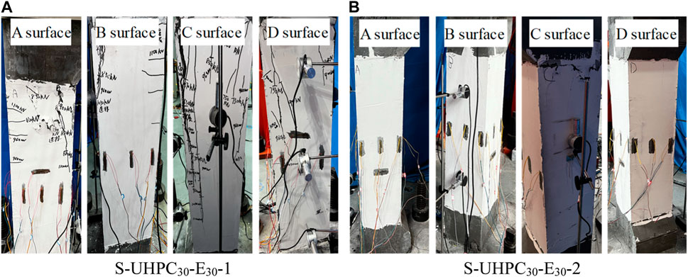
FIGURE 10. Failure modes of specimens. (A) S-UHPC30-E30-1. (B) S-UHPC30-E30-2.
3.3.2 Load–displacement behavior
The load–displacement curve of columns strengthened under the eccentric load is shown in Figure 11. The T1, T2, and V displacements of specimen S-UHPC30-E30-1 corresponding to the peak load were 6.51, 4.14, and 2.9 mm, respectively. The T1, T2, and V displacements of specimen S-UHPC30-E30-2 corresponding to the peak load were 5.78, 3.71, and 3.08 mm, respectively. Compared to the US-UHPC0-E30 group, the peak load of group S-UHPC30-E30 was increased by 757.31 kN (129%), which demonstrated the effectiveness of the masonry columns strengthened with UHPC under eccentric loading. It is worth noting that the displacements at T1 and T2 were increased by 2.45 (66%) and 1.73 mm (79%), respectively, while the displacements at V were decreased by 0.23 mm (7.7%). This indicated that UHPC can improve the transverse deformation of masonry columns and can confine the vertical deformation of masonry columns. Compared to the US-UHPC0-E0 and US-UHPC0-E30 groups, the load–displacement curves of masonry columns strengthened with UHPC exhibited non-linear characteristics near the peak loads, which showed better elastic–plastic deformability. It is interesting that the load-carrying capacity of the strengthened columns was more slowly degraded after the peak load, exhibiting a certain ductile failure characteristic. This can be explained by the bridging effect of steel fibers in the UHPC jacket, which restrained the crack expansion and lateral expansion of masonry columns. This indicated that using UHPC jacketing for masonry column strengthening was a reliable technique to enhance the load-bearing capacity and deformation of masonry columns, preventing brittle failure of masonry columns under compressive loads.
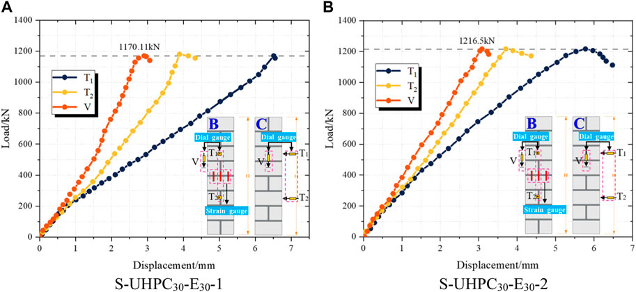
FIGURE 11. Load–displacement curves. (A) S-UHPC30-E30-1. (B) S-UHPC30-E30-2.
3.3.3 Load–strain curves
Based on experimental data, the load–strain curves for masonry columns strengthened with UHPC under the eccentric load were drawn. The load–strain curves for specimens strengthened with UHPC jackets are depicted in Figure 12. Positive values stand for tensile strain, and negative values stand for compressive strain.
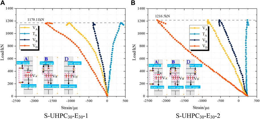
FIGURE 12. Load–strain curves. Note: VA is the vertical strain in the A surface, TA is the transverse strain in the A surface, VB is the vertical strain in the B surface, and VD is the vertical strain in the D surface. (A) S-UHPC30-E30-1. (B) S-UHPC30-E30-2.
As can be seen from Figure 12, the masonry columns are subjected to tension in the transverse direction and compression in the vertical direction under compression. It can be observed that when the load was small, the relationship between the load and strain was linear provided that the masonry column was in the elastic stage. With a further increase in load, the strain in masonry columns exhibited a non-linear development. At this moment, the specimen was in the plastic stage and the strain started to increase rapidly. The experimental results indicated that the masonry columns generated high compressive strains under peak loads, but most of the A surface strains did not pass the yield value.
For specimen S-UHPC30-E30-1, the strains of VA, TA, VB, and VD corresponding to the peak load were 1,042.92 με, 375.15 με, 382.79 με, and 1,643.51 με, respectively. For specimen S-UHPC30-E30-2, the strains of VA, TA, VB, and VD corresponding to the peak load were 849.15 με, 238.56 με, 533.87 με, and 2246.29 με, respectively. It can be seen that the strain at VD corresponding to the peak load was the highest and reached the yield state. This indicates that the performance of the UHPC layer on the D surface was adequately utilized at this point. In addition, it is notable that the strain in the near eccentric surface (D surface) was considerably higher than that in the opposite eccentric surface (B surface) under the same load. This can be attributed to the fact that the eccentric loads can lead to eccentric deformation of specimens, which, in turn, can induce their inhomogeneous strains.
3.4 Comparison of results
In this section, a comparison analysis of the results obtained in axial or eccentric compression tests for unstrengthened columns and columns strengthened with UHPC is presented. The failure modes and key results of all the specimens are shown in Table 5. In Table 5, both transverse and vertical displacements correspond to the peak load, εh is the ultimate constrained axial strain, and εcc is the ultimate constrained hoop strain.
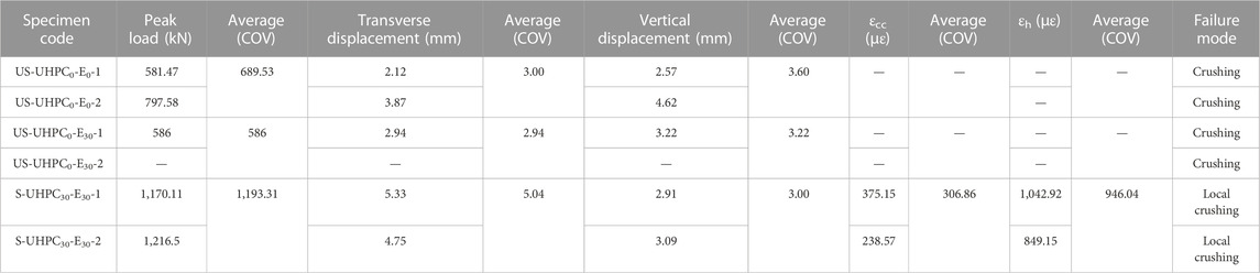
TABLE 5. Details of masonry columns and key results.
Brittle failure characteristics were observed in the unstrengthened columns. Due to the expansion of the masonry core, a very rapid destruction process was observed. On the contrary, the damage pattern for masonry columns constrained with UHPC was characterized by transverse cracks in the middle or upper part of specimens, with a relatively slow crack progression process. In terms of load-carrying capacity, the area of the compression zone of structures can be weakened by the eccentricity distance, which consequently decreased the load-carrying capacity of structures, with US-UHPC0-E30 being smaller than US-UHPC0-E0 by 103.53 kN (17.67%). However, the specimen strengthened by UHPC (S-UHPC30-E30) showed an increase in bearing capacity by 607.31 kN (103.64%). This demonstrated the effectiveness of UHPC in strengthening the eccentric members. Masonry columns strengthened with UHPC exhibited a greater transverse buckling deformation. The transverse displacements increased by 2.04 mm (68%) and 2.1 mm (71.43%), respectively, compared to US-UHPC0-E0 and US-UHPC0-E30. In contrast, the vertical displacements of strengthened masonry columns were constrained, and the vertical displacements of S-UHPC30-E30 declined by 0.6 mm (20%) and 0.22 mm (6.83%) compared to US-UHPC0-E0 and US-UHPC0-E30, respectively. When the specimen reached the ultimate load, the tensile and compressive strains on the A surface of the UHPC layer were 306.86 and 946.04 με, respectively. It is interesting to note that the strain values were extremely small. This can be attributed to the fact that the masonry interior has been destructed under ultimate loading, while UHPC has not completely cracked yet.
4 Theoretical predictions
4.1 Strengthening mechanism of UHPC jackets
Based on the aforementioned analysis of experimental results, it can be seen that the bearing capacity and failure modes of masonry columns strengthened with UHPC are extremely different from unstrengthened masonry columns. For hoop-strengthened masonry columns, an excellent bond between masonry and the UHPC layer exists, where both were subjected to forces and destroyed at the time of final failure. In the calculations, it is taken into account that masonry columns are subjected to practical forces with constant loads and corresponding initial strains. Hence, the effect of an initial stress level was considered theoretically. In addition, the influence of strengthening materials with various characteristics and hoop effects on the increase in load-bearing capacity of structures was comprehensively considered in the calculations.
4.2 Basic assumptions
Although masonry strengthening and UHPC strengthening have been studied in the literature, little research has been performed on the application of UHPC to masonry structures. In this paper, the code for the design of strengthening masonry column (GB 50702-2011) (GB 50702-2011, 2011), the code for the design of highway masonry bridges and culverts (JTG D61-2005) (JTG D61-2005, 2005), and the code for the design of strengthening concrete structure (GB 50367-013) (GB 50367-2013, 2013) are treated as the principles, and other materials are comprehensively considered for the study on masonry column strengthening. In order to simplify the calculation process, the following basic assumptions are used in the process of analysis:
(1) No relevant slips were observed between the UHPC layer and masonry column at the capacity limit state.
(2) The strain distribution on the column section conforms to the plane cross-section assumption. The variation in the vertical strain in the UHPC layer and masonry core under compression is equivalent.
(3) The impact of the UHPC layer constraining the masonry will be maintained before it is peeled away.
(4) The damage mode of masonry columns strengthened with UHPC is compression damage to the normal section.
4.3 Load-carrying prediction of strengthened masonry columns
4.3.1 Analysis of failure modes of UHPC-strengthened masonry columns
The calculation of masonry columns strengthened with UHPC is similar to the section-enlarging reinforced method of reinforced concrete. In practical strengthening, the upper part of the structure is subjected to non-unloadable constant loads (N1), resulting in a certain initial strain (
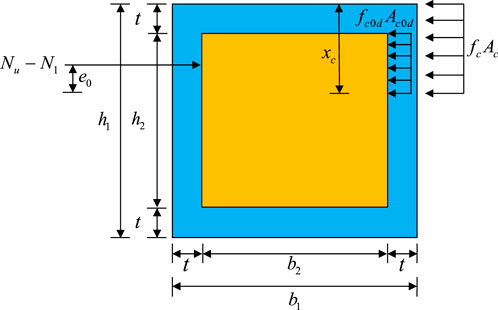
FIGURE 13. Analytical model of the ultimate bearing capacity.
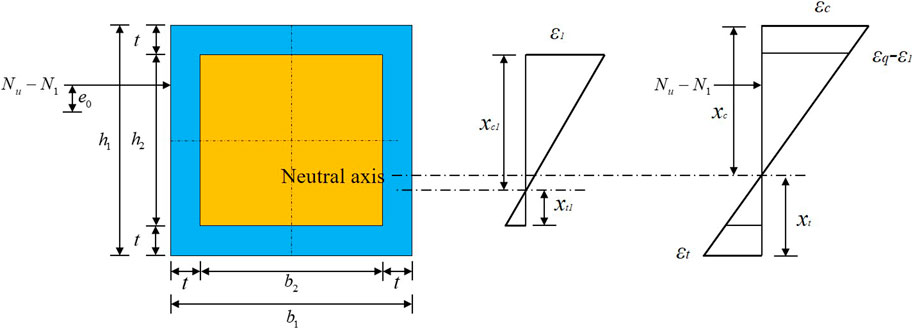
FIGURE 14. Strain distribution on the cross section.
As shown in Figure 14, the failure of the structure after strengthening can be divided into the following three main types:
(1) The edge of the UHPC layer first reached the maximum strain when the structure was damaged. The failure of the structure began with the cracking of the UHPC layer. For this case, the strain at the edge of the UHPC layer was
(2) The edge of masonry first reached the ultimate strain when the specimen was damaged. The failure of the structure began with the cracking of masonry. For this case, the strain at the edge of the masonry column was
(3) The edges of UHPC layer and masonry simultaneously reached the maximum stress and ultimate strain when the structure was damaged, i.e.,
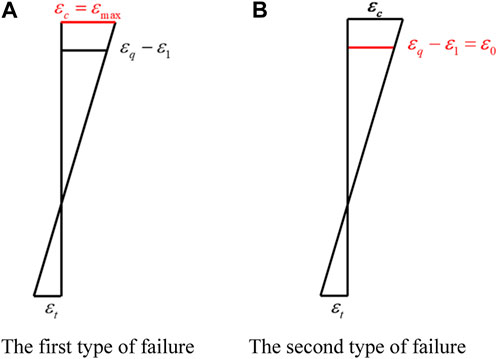
FIGURE 15. Strain distribution on the cross section. (A) First type of failure. (B) Second type of failure.
4.3.2 Calculation of the relative depth of the compression zone
Corresponding to the three failure types of the structure, there exist three types of relative depth of the compression zone.
(1) The UHPC layer edge in the compression zone reached its maximum strain when the first type of failure occurred in the structure. Meanwhile, UHPC in the tension zone reached its maximum tensile strain. The relative depth of the compression zone (
It can be seen that
(2) The masonry edge in the compression zone reached its maximum strain when the second type of failure occurred in the structure. Meanwhile, UHPC in the tension zone reached its maximum tensile strain. The relative depth of the compression zone (
It can be seen that
(3) When the third type of failure occurred in the structure,
4.3.3 Calculation of the ultimate bearing capacity of the normal section
By analyzing the failure type and relative depth of the compression zone for the strengthened structure, the corresponding formulas for calculating the ultimate bearing capacity can be obtained.
Based on the section equilibrium equation, the axial forces and bending moments on the cross section were calculated. The equilibrium equation can be expressed as follows:
where
According to Orange et al. (2013) and Hussein and Amleh (2015),
where
(1) The first type of failure
When
The bending moment equilibrium of cross sections can be expressed using Eq. 6:
where
In Eq. 7,
When
The bending moment equilibrium of point N can be expressed as shown in Eq. 10:
(2) The second type of failure
When
The bending moment equilibrium of point N can be given by Eq. 12:
When
The bending moment equilibrium of point N can be expressed as shown in Eq. 14:
4.4 Comparison between experimental and theoretical predictions
In this section, the strength increases obtained in the current experimental study were compared with those deduced from the equations derived previously and those derived from the analytical expressions existing in the literature. Owing to the lack of codes and models for UHPC-constrained masonry, BMHDC- and FRP-constrained models were chosen in this paper. Based on the work in Ref., two models were selected to predict the strength gain in this study, i.e., the second-order analysis model proposed by Li et al. (2021) and the Italian guidelines CNR model (CNR-DT 200 R1 2013, 2013).
The second-order analysis model was used for masonry columns with the confinement of BMHDC, which is formulated as follows:
where
Referring to the CNR model and literature (El-Sokkary and Khaled, 2019), the expression for the compressive strength of the eccentric specimen in this experiment is given as follows:
where
The theoretical and test results of the ultimate bearing capacity are given in Table 6. It can be found that the ratio of the calculated values to experimental values was 1.09–1.14, which indicates that the accuracy of this formula in predicting masonry columns strengthened with UHPC was high. It is also worth noting that the calculated values were higher than the experimental values. This can be explained by the fact that the formula was proposed on the assumption that UHPC is well bonded to the masonry in this paper. In contrast, the bonding of specimens was weakened in the laboratory due to fabrication and handling. Hence, the calculation method proposed in this paper can provide a reference for strengthening calculations involving better bonding between UHPC and masonry structures. However, it can be observed that the final results for using both second-order and CNR models were larger relative to the experimental results. This can be explained in two aspects: (a) the existence of initial strains in the structure was not considered, resulting in oversized predictions; (b) the high ductility of steel fibers in UHPC, which will generate a tensile effect on the structure.
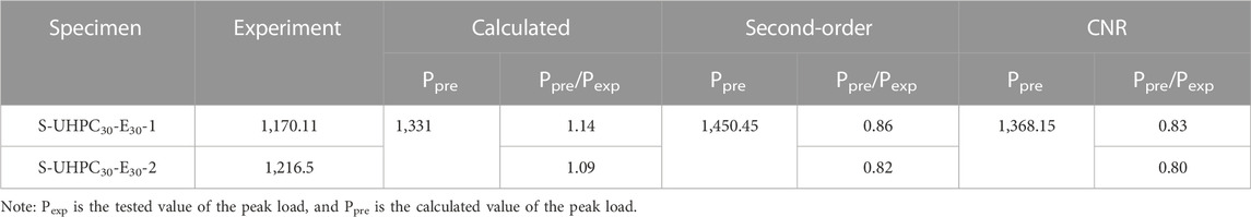
TABLE 6. Comparison of compressive strength between test results and theoretical values.
5 Conclusion
The force behavior of masonry columns strengthened with UHPC jackets under eccentric compressive loading was investigated by means of six masonry columns subjected to compressive experimental studies and theoretical analyses. The influence of initial stress on the bearing capacity of strengthened columns was discussed, and the following conclusions are drawn.
(1) The damage mode of masonry columns strengthened with UHPC jackets under compressive conditions was modified. Certain brittle damage characteristics were exhibited in unstrengthened masonry columns. The masonry columns strengthened with UHPC jackets showed excellent elastic–plastic deformation capacity after peak loading, with a ductile failure mode.
(2) The peak load and deformation capacity of masonry columns strengthened with UHPC jackets were significantly increased. Compared with the US-UHPC0-E30 group, the peak load of masonry columns strengthened with UHPC increased by 103.64%. The transverse displacement of the S-UHPC30-E30 masonry column increased by 71.43% and the vertical displacement increased by −6.83%. This phenomenon demonstrated the effectiveness of masonry columns strengthened with UHPC under eccentric loading.
(3) Non-uniform distribution of the vertical strain was observed in the UHPC composite masonry columns. Meanwhile, the strain growth rate in the near-eccentric side was much higher than that in any other side. The inconsistency of the strain growth rate may be attributed to the complex deformation of masonry columns under eccentric loading.
(4) Based on the experimental results, the equation for predicting the ultimate bearing capacity of UHPC-strengthened masonry columns was proposed. With good bonding of the UHPC layer to the masonry section, the experimental values were in good agreement with the calculated values.
In conclusion, the aforementioned experimental and theoretical studies proved that UHPC jacketing was an effective strengthening technology in enhancing the bearing capacity of eccentric compressed masonry columns. However, the number of samples in this study was too small owing to time and field conditions. In future experiments, more tests on masonry structures strengthened by UHPC should be carried out, including the thickness of UHPC, the interface treatment type, and the masonry material. Meanwhile, further research on the size effect on full-size members should be conducted to obtain general conclusions.
Data availability statement
The original contributions presented in the study are included in the article/Supplementary Material. Further inquiries can be directed to the corresponding author.
Author contributions
YZ: conceptualization, methodology, formal analysis, and writing—reviewing and editing; PJ: supervision; HS: resources and data curation; JL: validation and writing—original draft; RC: investigation; ZJ: data curation. All authors contributed to the article and approved the submitted version.
Acknowledgments
The authors acknowledge the financial support from the National Natural Science Foundation of China (Grant Nos 52278293 and U20A20314).
Conflict of interest
The authors declare that the research was conducted in the absence of any commercial or financial relationships that could be construed as a potential conflict of interest.
Publisher’s note
All claims expressed in this article are solely those of the authors and do not necessarily represent those of their affiliated organizations, or those of the publisher, the editors, and the reviewers. Any product that may be evaluated in this article, or claim that may be made by its manufacturer, is not guaranteed or endorsed by the publisher.
References
AFGC-SETRA (2002). Ultra-high-performance fiber-reinforced concrete, interim recommendations. Pairs, France: AFGC publication.
Alotaibi, K. S., and Galal, K. (2018). Experimental study of CFRP-confined reinforced concrete masonry columns tested under concentric and eccentric loading. Compos. Part B Eng. 155, 257–271. doi:10.1016/j.compositesb.2018.08.024
Azmee, N. M., and Shafiq, N. (2018). Ultra-high performance concrete: from fundamental to applications. Case. Stud. Constr. Mater. 9, e00197. doi:10.1016/j.cscm.2018.e00197
Babatunde, S. A. (2017). Review of strengthening techniques for masonry using fiber reinforced polymers. Compos. Struct. 161, 246–255. doi:10.1016/j.compstruct.2016.10.132
Beglarigale, A., Eyice, D., Tutkun, B., and Yazıcı, H. (2021). Evaluation of enhanced autogenous self-healing ability of UHPC mixtures. Constr. Build. Mater. 280, 122524. doi:10.1016/j.conbuildmat.2021.122524
Cevallos, O. A., Olivito, R. S., Codispoti, R., and Ombres, L. (2015). Flax and polyparaphenylene benzobisoxazole cementitious composites for the strengthening of masonry elements subjected to eccentric loading. Compos. Part B Eng. 71, 82–95. doi:10.1016/j.compositesb.2014.10.055
Chen, Y. (2021). Experimental study on compressive bearing capacity of existing masonry structures strengthened by UHPC. Hebei, China: North China University of Science and Technology.
CNR-DT 200 (R1 2013) (2013). Guide for the design and construction of externally bonded FRP systems for strengthening existing structures. Rome: Italian Council of Research CNR.
Corradi, M., Grazini, A., and Borri, A. (2007). Confinement of brick masonry columns with CFRP materials. Compos. Sci. Technol. 67, 1772–1783. doi:10.1016/j.compscitech.2006.11.002
de Larrard, F., and Sedran, T. (1994). Optimization of ultra-high-performance concrete by the use of a packing model. Cem. Concr. Res. 24, 997–1009. doi:10.1016/0008-8846(94)90022-1
Deng, M., and Li, T. (2020). Masonry columns strengthened with bar mesh highly ductile fiber reinforced concrete (BMHDC) jacket under concentric and eccentric loads. Constr. Build. Mater. 237, 117606. doi:10.1016/j.conbuildmat.2019.117606
El-Sokkary, H., and Khaled, G. (2019). Performance of eccentrically loaded reinforced-concrete masonry columns strengthened using FRP wraps. J. Compos. Constr. 23 (5), 958. doi:10.1061/(asce)cc.1943-5614.0000958
Fayala, I., Limam, O., and Stefanou, I. (2016). Experimental and numerical analysis of reinforced stone block masonry beams using GFRP reinforcement. Compos. Struct. 152, 994–1006. doi:10.1016/j.compstruct.2016.06.046
GB 50367-2013 (2013). Code for design of strengthening concrete structure. Beijing, China: China Architecture & Building Press.
GB 50702-2011 (2011). Code for design of strengthening masonry structures. Beijing, China: China Architecture & Building Press.
GB/T 31387-2015 (2015). Reactive powder concrete. Beijing, China: General Administration of Quality Supervision, Standards Press of China Press.
Guan, D., Xu, R., Yang, S., Chen, Z., and Guo, Z. (2022). Development and seismic behavior of a novel UHPC-shell strengthened prefabricated concrete column. J. Build. Eng. 46, 103672. doi:10.1016/j.jobe.2021.103672
Haber, Z. B., Munoz, J. F., De la Varga, I., and Graybeal, B. A. (2018). Bond characterization of uhpc overlays for concrete bridge decks: laboratory and field testing. Constr. Build. Mater. 190, 1056–1068. doi:10.1016/j.conbuildmat.2018.09.167
Hussein, L., and Amleh, L. (2015). Structural behavior of ultra-high performance fiber reinforced concrete-normal strength concrete or high strength concrete composite members. Constr. Build. Mater. 93, 1105–1116. doi:10.1016/j.conbuildmat.2015.05.030
JTG D61-2005 (2005). Code for design of highway masonry bridges and culverts. China: People’s Communications Press.
JTG E41-2005 (2005). Test methods of rock for highway engineering. Beijing, China: China Communications Press.
Lampropoulos, A., Tsioulou, O., and Dritsos, S. E. (2017). Strengthened unreinforced masonry (URM) structures with ultra high performance fibre reinforced (UHPFRC) layers under axial in-plane and horizontal out-of-plane loading. IABSE Symp.
Lee, M., Wang, Y., and Chiu, C. (2007). A preliminary study of reactive powder concrete as a new repair material. Constr. Build. Mater. 21, 182–189. doi:10.1016/j.conbuildmat.2005.06.024
Li, T., Deng, M., and Zhang, Y. (2021). Effect of eccentricity on strengthening efficiency of bar mesh high ductile concrete (BMHDC) on slender masonry columns. Eng. Struct. 230, 111732. doi:10.1016/j.engstruct.2020.111732
Ombres, L., and Verre, S. (2015). Structural behaviour of fabric reinforced cementitious matrix (FRCM) strengthened concrete columns under eccentric loading. Compos. Part B Eng. 75, 235–249. doi:10.1016/j.compositesb.2015.01.042
Orange, G., Acker, P., and Dugat, J. (2013). Damage resistance and micromechanical analysis of ultra high performance concrete. Ecf 13 San Sebastian.
Peng, B., Wei, S. D., Long, L. B., Zheng, Q. Z., Ma, Y. Q., and Chen, L. Y. (2019). Experimental investigation on the performance of historical squat masonry walls strengthened by UHPC and reinforced polymer mortar layers. Appl. Sci. 9 (10), 2096. doi:10.3390/app9102096
Richard, P., and Cheyrezy, M. (1995). Composition of reactive powder concretes. Cem. Concr. Res. 25, 1501–1511. doi:10.1016/0008-8846(95)00144-2
Richard, P., and Cheyrezy, M. (1994). Reactive powder concretes with high ductility and 200-800 MPa compressive strength. ACI Sp. 144, 507–518.
Schmidt, M., and Fehling, E. (2005). Ultra-high-performance concrete: research development and application in europe. ACI Sp. 228, 51–56. doi:10.1016/j.bioeng.2004.09.004
T/CBMF 37-2018 (2018). Fundamental characteristics and test methods of ultra-high performance concrete. Beijing, China: China Building Materials Industry Press.
Vincent, T., and Ozbakkaloglu, T. (2013). Influence of fiber orientation and specimen end condition on axial compressive behavior of FRP-confined concrete. Constr. Build. Mater. 47, 814–826. doi:10.1016/j.conbuildmat.2013.05.085
Wan, C., Wang, J., Zeng, Q., Shen, L., Yan, D., and Peng, Y. (2021). Mechanical behavior of masonry columns strengthened with basalt textile reinforced concrete under eccentric loading: experimental investigation and analytical modelling. Constr. Build. Mater. 269, 121816. doi:10.1016/j.conbuildmat.2020.121816
Wang, C., Sarhosis, V., and Nikitas, N. (2018). Strengthening/retrofitting techniques on unreinforced masonry structure/element subjected to seismic loads: A literature review. Open constr.build. Technol. J. 12, 251–268. doi:10.2174/1874836801812010251
Wang, J., Wan, C., Zeng, Q., Shen, L., Malik, M. A., and Yan, D. (2020). Effect of eccentricity on retrofitting efficiency of basalt textile reinforced concrete on partially damaged masonry columns. Compos. Struct. 232, 111585. doi:10.1016/j.compstruct.2019.111585
Wang, Z., Yang, J., Zhou, J., Yan, K., Zhang, Z., and Zou, Y. (2022). Strengthening of existing stone arch bridges using UHPC: theoretical analysis and case study. Struct 43, 805–821. doi:10.1016/j.istruc.2022.06.055
Witzany, J., Čejka, T., and Zigler, R. (2014). Failure mechanism of compressed short brick masonry columns confined with FRP strips. Constr. Build. Mater. 63, 180–188. doi:10.1016/j.conbuildmat.2014.04.041
Yang, J., Chen, R., Zhang, Z., Zou, Y., Zhou, J., and Xia, J. (2023). Experimental study on the ultimate bearing capacity of damaged RC arches strengthened with ultra-high performance concrete. Eng. Struct. 279, 115611. doi:10.1016/j.engstruct.2023.115611
Yang, J., Xia, J., Zhang, Z., Zou, Y., Wang, Z., and Zhou, J. (2022). Experimental and numerical investigations on the mechanical behavior of reinforced concrete arches strengthened with UHPC subjected to asymmetric load. Struct 39, 1158–1175. doi:10.1016/j.istruc.2022.03.087
Yang, Z., and Cheng, X. (2013). A performance study of high-strength microbial mortar produced by low pressure grouting for the reinforcement of deteriorated masonry structures. Constr. Build. Mater. 41, 505–515. doi:10.1016/j.conbuildmat.2012.12.055
Yazıcı, H., Yardımcı, M. Y., Aydın, S., and Karabulut, A. Ş. (2009). Mechanical properties of reactive powder concrete containing mineral admixtures under different curing regimes. Constr. Build. Mater. 23, 1223–1231. doi:10.1016/j.conbuildmat.2008.08.003
Zhang, Z., Pang, K., Xu, L., Zou, Y., Yang, J., and Wang, C. (2023). The bond properties between UHPC and stone under different interface treatment methods. Constr. Build. Master. 365, 130092. doi:10.1016/j.conbuildmat.2022.130092
Zhou, M., Lu, W., Song, J., and Lee, G. C. (2018). Application of ultra-high performance concrete in bridge engineering. Constr. Build. Mater. 186, 1256–1267. doi:10.1016/j.conbuildmat.2018.08.036
Zou, Y., Yu, K., Heng, J., Zhang, Z., Peng, H., Wu, C., et al. (2023a). Feasibility study of new GFRP grid web-Concrete composite beam. Com. Struct. 305, 116527. doi:10.1016/j.compstruct.2022.116527
Keywords: ultra-high performance concrete, masonry columns, strengthening, compressive performance, theoretical predictions
Citation: Zhang Y, Jiang P, Song H, Leng J, Chen R and Jiang Z (2023) Experimental study on the eccentrically compressive performance of square masonry columns repaired with UHPC jackets. Front. Mater. 10:1232768. doi: 10.3389/fmats.2023.1232768
Received: 01 June 2023; Accepted: 11 September 2023;
Published: 02 October 2023.
Edited by:
Jing Yu, The University of Hong Kong, Hong Kong SAR, ChinaReviewed by:
Peng Wang, Hong Kong University of Science and Technology, Hong Kong SAR, ChinaLuciano Ombres, University of Calabria, Italy
Copyright © 2023 Zhang, Jiang, Song, Leng, Chen and Jiang. This is an open-access article distributed under the terms of the Creative Commons Attribution License (CC BY). The use, distribution or reproduction in other forums is permitted, provided the original author(s) and the copyright owner(s) are credited and that the original publication in this journal is cited, in accordance with accepted academic practice. No use, distribution or reproduction is permitted which does not comply with these terms.
*Correspondence: Peng Jiang, MTE1MTg5ODE0MUBxcS5jb20=