 Yingna Mu
 Qibing Hu1
 Yanbin Tan
94% of researchers rate our articles as excellent or good
Learn more about the work of our research integrity team to safeguard the quality of each article we publish.
Find out more
ORIGINAL RESEARCH article
Front. Mater., 10 August 2023
Sec. Structural Materials
Volume 10 - 2023 | https://doi.org/10.3389/fmats.2023.1229930
This article is part of the Research TopicAdvanced Materials and Techniques for Structural Monitoring, Analysis and ControlView all 16 articles
To ensure the safe operation of bridges, the study of methods and techniques for boom replacement has become a crucial aspect of the scientific maintenance of suspension bridges. This study focuses on analyzing the bridge responses and evaluating the applicability of three different boom replacement methods: single-point, three-point and five-point, using finite element calculations. A sea-crossing suspension bridge is taken as a case study to simulate the process of boom replacement using temporary booms. Consequently, the optimal replacement method for booms of varying lengths is determined. Meanwhile, this research proposes a quantitative basis for classifying boom lengths based on calculation data and analysis results to determine the suitable boom lengths for different replacement methods. Besides, a comparison of the relationship between the force transmission efficiency of temporary booms and boom length reveals that longer booms exhibit lower force transmission efficiency, with the efficiency decreasing at a faster rate as boom length increases. Overall, these findings provide a theoretical basis for the study of boom replacement in suspension bridges.
With the improvement of China’s economic level and engineering construction capacity, a lot of long-span suspension bridges (Huang and Zhang, 2021) have been constructed across canyons, rivers, streams, and sea areas throughout the country. However, these bridges are inevitably subjected to performance degradation due to harsh environmental conditions. Therefore, studying the maintenance of suspension bridges is of utmost importance. The boom plays a crucial role as a force transmission element in suspension bridges, connecting the main cable and the main beam while transferring the self-weight of the main beam and various loads to the main cable, tower, and anchorage structure. Therefore, the function and condition of the boom are closely intertwined with the safe operation of suspension bridges. Once a bridge is put into service, the boom undergoes gradual changes in appearance, mechanics, material properties, and other aspects due to external environmental factors, permanent and variable actions, and even accidents. As a result, various defects may arise, posing risks to the bridge’s safety. Available data indicates that within 2–3 years of operation, several issues such as cracking of the protective layer, component corrosion, steel wire corrosion, cable body water seepage, and shaft sleeve wear have been observed to varying degrees in some bridges (Cao, 2020; Dou, 2020; Han, 2020). Rust greatly reduces the fatigue life of a single steel wire in the suspension boom. As a vulnerable structure, the service life of the suspension boom is generally 20 years (Xu, 2020; Yang and Lu, 2022). The Technical Code of Maintenance for City Bridge specifies that the replacement of booms should be considered if the wire breaking rate of the cable exceeds 2%, or the section reduction caused by corrosion of the steel wire exceeds 10% (Sun, 2014).
Numerous examples of boom replacement in suspension bridges can be found at home and abroad. Specifically, all booms of the Forth Road Bridge in the United Kingdom were replaced after 40 years from its opening to traffic in September 1964 (Alastair and Colford, 2017). The Aquitaine Bridge in France underwent a complete overhaul of its cable system as a result of main cable corrosion (Li, 2021). All booms of the Lions Gate Bridge in Vancouver Canada were replaced in around 2000, marking the world’s first instance of boom replacement for an entire bridge without interrupting traffic (Radojevic et al., 2019). Four groups of booms in the Shantou Bay Bridge were replaced by engineering personnel in 2012 due to significant deterioration during the bridge’s extended period of service (Wang et al., 2015). Urgent boom replacements were carried out on the Jiangsu Runyang Bridge in 2017 following severe fire damage (Yuan et al., 2021), and all booms of the Fushun Tianhu Bridge were replaced in 2015 (Yu et al., 2019).
Despite numerous examples of boom replacement projects at home and abroad, limited research has been conducted on the technology and theory of boom replacement in suspension bridges. Yu Zh et al. (Yu et al., 2019) simulated the boom replacement process using the temporary boom method in finite element software in 2019. Their study revealed a significant 38.9% reduction in the tensile force of the temporary boom in the three-point replacement method compared to the single-point replacement method. However, the temporary boom in the five-point replacement method exhibited a 9.9% lower tensile force than that in the three-point replacement method. With only the adjacent booms on both sides of the replacement boom greatly affected during the replacement. To address the long construction duration associated with boom replacement, Yuan et al. (2021) designed and developed a self-balancing tensioning and thrusting equipment specifically for boom replacement construction. The equipment was successfully applied in the boom construction of the Runyang Bridge, effectively minimizing the interference of displacement and internal forces caused by boom replacement. However, this equipment is only suitable for bridges with steel box beams and lifting lug anchor plates, and pin control should be reserved. Wang et al. (2015) in response to the defects observed on the booms of the Shantou Bay Bridge, conducted a replacement test on representative booms. And proposed a replacement construction scheme through discussions on the scheme and method of boom replacement. Huang and Zhang. (2021) compared the construction plans for replacing long and short booms and found that the method with a single lifting point for releasing the tensile force, followed by simultaneous graded tensioning and dismantling of the old boom is generally applicable for replacing short booms. The multi-point lifting scheme, although suitable for replacing long booms and minimizing impacts on bridge alignment, has disadvantages such as requiring numerous temporary booms, heavier construction workloads, and higher costs. Zeng et al. (2016) thought that the stress condition of short booms is more complex than that of long booms and provided insights into the stress transmission mode and damage mechanism of booms. As short booms can experience a combination of static and dynamic loads, separate calculation of their dynamic characteristics becomes necessary. Liu et al. (2023) used the method of matrix analysis and transforming multiple objectives into a single objective to determine the adjustment amount of boom length, adjust the boom force and actual deck elevation. Then achieve the comparison and selection of boom replacement schemes for a steel truss suspension bridge. Three-dimensional finite element analyses were employed by Süleyman et al. (2023) for both inclined and vertical boom configurations of the Bosporus Suspension Bridge. Fan et al. (2023) presented a robustness-based condition evaluation framework for the overall structure. The evaluation processes of three conditions are further presented in accordance with the suspension bridge, and the variation in the potential risk of accidents induced by cable failure is shown intuitively through the evaluation results.
The design service life of bridges is generally long, and in such a long service period, the performance of bridges will inevitably deteriorate due to the harsh environment, especially for long-span suspension bridge. In order to maintain the safe operation of the bridge, the research on boom replacement has also received more and more attention. It has become an important part of scientific maintenance, which is of great significance for scientific guidance of bridge maintenance. From the above analysis, it can be clearly seen that the cable system is an extremely important part of the suspension bridge, the boom configuration has a positive impact in terms of vertical displacement and internal forces obtained. Thus the safe operation of the bridge structure has very high requirements for the accuracy of the boom replacement process. The full bridge structure and components will all respond to changes with the tension of the temporary boom. Therefore, the study on the adaptability of boom replacement methods, the optimization in the process of boom replacement with various lengths, as well as the response analysis of the structure and components is crucial.
This paper focuses on studying the adaptability of boom replacement methods and the response of the bridge structure, using a sea-crossing bridge as a case study. The bridge under investigation is a three-span earth-anchored double-deck suspension bridge located in the Yellow Sea area of China, spanning from the east to the west. The bridge was completed and opened to traffic in 2015. The computed span of the bridge is 180 m + 460 m+180 m = 820 m. The bridge features two main cables, each consisting of 7747 high-strength galvanized parallel steel wires with a diameter of 5.2 mm. Meanwhile, a total of 158 hanging points is distributed along the bridge, with two booms arranged at each hanging point. The ordinary flexible boom consists of 73 high-strength galvanized steel wires with a diameter of 7 mm, covered with a protective layer made of PE material. In addition, central buckle stay cables are installed at the mid-span. The bridge incorporates a portal tower that stands 112.31 m high. The column of the tower is designed as a “D"-shaped hollow reinforced concrete structure with a variable section, while the upper crossbeam is constructed using prestressed concrete. The main steel truss beam is 10 m high, and all structural members are constructed with closed box sections. Moreover, the double-deck system of the bridge consists of orthotropic plates, with a 55 mm layer of asphalt paving on the steel plates. The deck is designed as a one-way four-lane system, with the upper layer facilitating traffic from east to west and the lower layer accommodating traffic from west to east. The overall configuration of the bridge is illustrated in Figure 1. Unit number and spatial location of the booms are shown in Figures 2, 3. The short boom analyzed in the paper is No. 122, with a length of 3.13 m, the medium boom is No. 93, with a length of 35.40 m and the long boom is No. 102, with a length of 56.75 m.
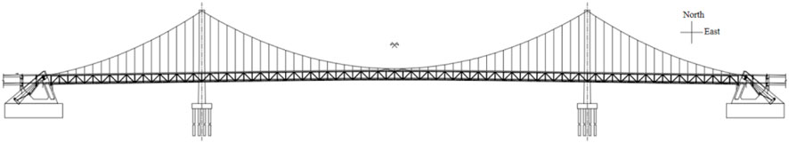
FIGURE 1. The sea crossing suspension bridge.
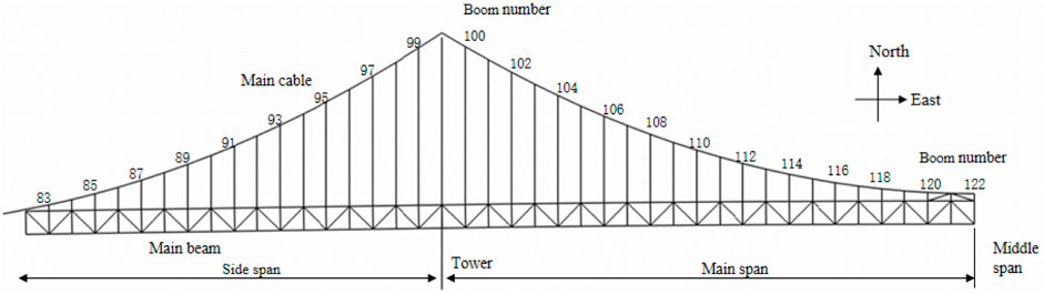
FIGURE 2. Unit number and spatial location map of boom.
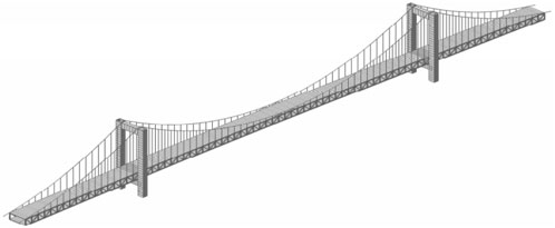
FIGURE 3. Model drawing of the suspension bridge.
The full bridge model was established using MIDAS Civil finite element software, incorporating appropriate simplifications and equivalences to ensure the feasibility and accuracy of the finite element analysis. Specifically, the main cable and booms were modeled as the equivalent section of 1860 steel wire in tension only. The bridge tower was modeled as a C50 concrete box hollow beam element with an equivalent section. The double-layer main beam was modeled as a non-closed box section, while the vertical and inclined web members were represented using beam elements. Correctly establishing the boundary conditions was crucial to ensure that the deformation and displacement of the bridge closely matched the actual situation. General supports were placed at both ends of the main beam to restrict vertical and transverse bridge displacement, while releasing longitudinal constraints to enable free movement and stress release. Besides, the stress state of the truss was accurately simulated by releasing beam end constraints for the vertical and inclined web members. The force transmission relationship between the main beam and the boom was established through rigid connections, consolidating the bottom of the tower and the two ends of the main cable. To ensure result accuracy, an independent model analysis method for nonlinear analysis was adopted during the operational analysis stage.
Currently, the temporary support method, temporary basket-hanging method, and temporary boom method are commonly employed for boom replacement, each with its own set of advantages and disadvantages. In this study, the temporary boom method was selected as it is widely utilized in practical applications. The fundamental principle of this method involves utilizing a temporary stress system to transfer the tensile force from the boom undergoing replacement, enabling the removal of the old boom and installation of the new one. Subsequently, the tensile force is once again transferred from the temporary stress system to the newly installed boom.
Besides, this study focused on the short boom located at the mid-span as the research object, analyzing the impact of boom replacement with the single-point method on the bridge. To accurately capture the response of each bridge component during the boom replacement process, it was necessary to ensure the temporary boom was evenly tensioned in stages. Therefore, the tension of the temporary boom was simulated by applying opposite node loads at both end nodes of the boom undergoing replacement using the MIDAS Civil finite element software (as shown in Figure 4).

FIGURE 4. Schematic diagram of single-point tensioning of mid-span and short booms.
The axial force of the temporary boom, tensioned in stages, is presented in Table 1. Upon completion of the tensioning process, the total axial force of the temporary boom exhibited a slight increase of 2.20% compared to the initial axial force of the replaced boom. The replacement of the short boom using the single-point method had a minimal impact on the vertical displacement of the main beam. Following the tensioning of the temporary boom, only the node of the main cable at the replaced boom experienced a downward displacement of −2.7 mm (as shown in Figure 5). Other nodes remained largely unaffected, and the cable maintained its alignment without significant changes. The vertical displacement of the main cable and beam at the mid-span experienced a sudden change due to the central buckle stay cables set.
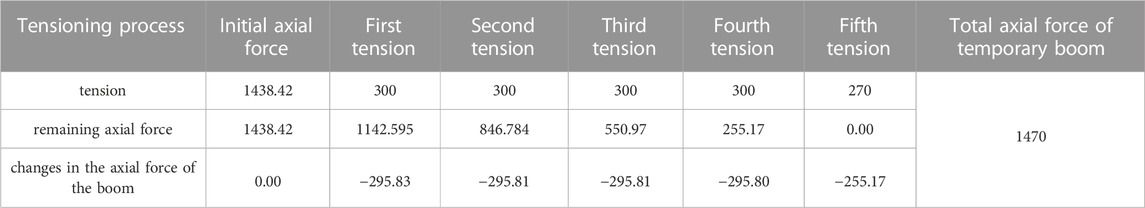
TABLE 1. Variation of the axial force in the uniform tension of the short boom at the mid-span (KN).
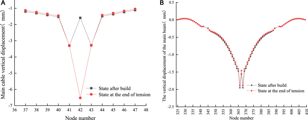
FIGURE 5. (A) Vertical displacement of the main cable nodes when the short boom at the mid- span is uniformly tensioned by the single-point method (B). Vertical displacement of the main beam on the upper floor when the short boom at the mid-span is uniformly tensioned by the single-point method.
Similarly, opposite node loads are applied for the replacement of medium-length booms. The staged tensioning of the temporary boom is shown in Table 2, indicating the corresponding axial forces. Since the upper node of the temporary boom is connected to the main cable, when the temporary boom is tensioned, the axial force applied to its upper node will also be transmitted to the main cable. According to the vertical displacement of the main cable node (Figure 6A), node 12 exhibited a significant downward displacement of −43.51 mm, while nodes 11 and 13 experienced smaller displacements of −5.97 mm and −7.45 mm, respectively. Other cable nodes showed minimal displacement. It can be concluded that the main cable nodes at the boom undergoing replacement and the adjacent boom will be significantly affected during the replacement of the medium boom using the single-point method. However, the impact on the main cable nodes at other locations is relatively minor. Meanwhile, as the upper node (node 12) of the replaced boom is connected to the main cable, its applied force combines the remaining axial force of the replaced boom and the tensioning axial force of the temporary boom, resulting in a downward movement of the main cable node. Secondly, at the end of the tensioning process, the axial force of the temporary boom slightly exceeded the initial axial force of the replaced boom. This increased force disrupted the initial equilibrium state of the main cable, leading to a significant downward displacement of the main cable node.
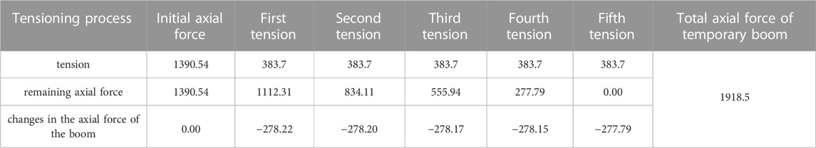
TABLE 2. Axial force change when a boom with a side span of medium length is tensioned by the single-point method (KN).

FIGURE 6. (A) Vertical displacement of the main cable at the side span. Figure 6 (B) The vertical displacement of the main beam on the upper floor when the mid-length boom of the side span is tensioned by the single-point method.
The vertical displacement of the upper main beam is shown in Figure 6B. The main beam displacement underwent an abrupt change at the position of the temporary boom, resulting in an upward displacement of 0.45 mm. At the same time, an upward displacement of 0.72 mm occurred at the mid-span, which is the maximum displacement at the main beam of the bridge. However, the main beam of the east side span remained unaffected. In addition, the geometric shape of the main beam in the main span underwent significant changes following tensioning, deviating from its finished bridge state. Due to the substantial rigidity of the main beam, the section at the temporary boom experienced an upward movement, thereby altering the internal force transmission mechanism to some extent. Moreover, the main beam in the main span also exhibited an upward displacement influenced by the integrity of the main beam.
Similarly, the long boom underwent staged tensioning during the displacement. The applied tension and the remaining axial force throughout the tensioning process is shown in Table 3. The axial force of the replaced boom was uniformly reduced during the uniform tensioning process, which aligns with the observations made during the replacement of the short and medium booms. This consistency indicates that the axial force of the replaced boom exhibited a linear change pattern when the single-point method was employed for replacing short, medium, and long booms. Furthermore, at the end of the tensioning process for the long boom replacement, the total axial force of the temporary boom significantly exceeded the initial axial force of the replaced boom by 812.05 KN, about 58.38% of the initial axial force.

TABLE 3. Variation of the axial force in the uniform tension of the long booms of the main span (KN).
In the case of replacing the long boom using the single-point method, the main cable node located at the position of the replaced boom experienced a significant downward displacement of −70 mm at the end of the temporary boom tensioning (Figure 7A). Meanwhile, the main cable node at the first adjacent boom underwent a downward displacement of −16.64 mm, while the second adjacent boom experienced a downward displacement of −3.96 mm. However, the main cable nodes that are farther away remained largely unaffected. These findings demonstrate that the vertical displacement and the extent of influence were relatively substantial, indicating that the single-point method is not suitable for replacing long booms.
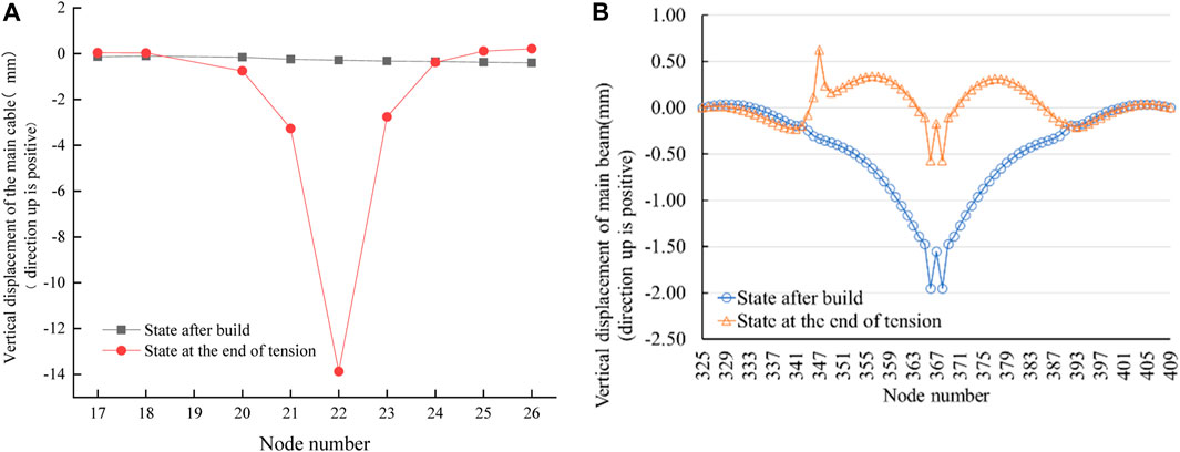
FIGURE 7. (A) Vertical displacement of the main cable when the main span long boom is tensioned by the single-point method. (B). Vertical displacement of the main beam on the upper floor when the long boom of the main span is tensioned by the single-point method.
The vertical displacement of the upper main beam is shown in Figure 7B, showing an abrupt change in displacement at the location of the temporary boom, resulting in an upward displacement of 0.96 mm. Besides, it is observed that the main beam in the main span exhibited an upward movement compared to its finished bridge state. The main beam in the east side span remained unaffected, while the alignment of the main beam in the main span underwent significant changes after tensioning. In particular, a maximum displacement of 1.38 mm occurred at the mid-span. This discrepancy in displacement can possibly be attributed to the redistribution of internal forces and changes in the transmission mechanism of the main beam during the replacement, causing the displacement at the mid-span to be greater at the temporary boom.
In the case of boom replacement using the temporary boom method, theoretically, the axial force of the temporary boom should be equal to the initial axial force of the replaced boom in its finished state. However, the results of numerical simulation analysis indicate that they are not equal. This finding aligns with the conclusions drawn by Yu Zhanglong (Yu et al., 2019) in a numerical simulation of a suspension bridge. It was suggested that this phenomenon is primarily influenced by the overall stiffness of the bridge and the boom replacement method employed. Specifically, a higher overall stiffness of the bridge results in a lower force transmission efficiency of the temporary boom during the boom replacement process.
To accurately study the influencing factors of force transmission efficiency, the computational formula of force transmission efficiency was proposed to quantitatively analyze the force transmission efficiency:
Where
The force transmission efficiency can be influenced by various factors, including the length of the boom, the replacement method used, and the initial axial force of the boom. The relationship between force transmission efficiency and boom length was studied with the single-point method, and numerical simulation analysis was conducted specifically on main span booms using the reference stress free state method. This approach ensured a continuous variation in boom length. Refer to Figures 2, 8 for details. Besides, the study on force transmission efficiency involved the analysis of 23 booms ranging from the short boom in the mid-span to the long boom adjacent to the tower in the west. The corresponding data for analysis are shown in Table 4.
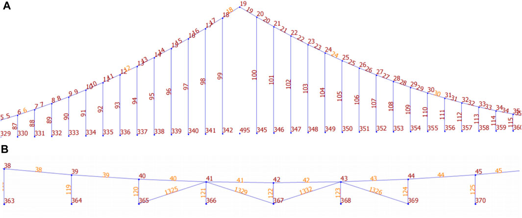
FIGURE 8. (A, B) Spatial location map of boom.
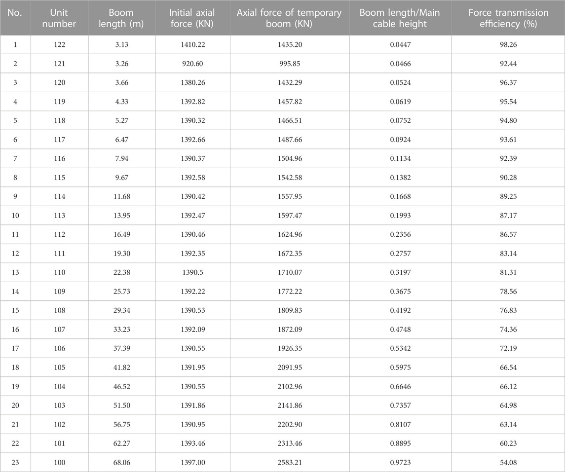
TABLE 4. Force transmission efficiency of temporary booms.
As shown in the relationship between force transmission efficiency and length of the boom (Figure 9), the force transmission efficiency of the shortest boom reached 98.26%, while booms with lengths less than 10 m maintained a force transmission efficiency above 90%. In contrast, the force transmission efficiency of booms with lengths exceeding 50 m decreased to below 70%. This trend indicates that the reduction in force transmission efficiency increased with increasing boom length, underscoring the high applicability of the single-point method for replacing short booms. Based on these results, booms with lengths under 10 m in the sea crossing suspension bridge can be defined as short booms. At the same time, it was observed that the ratio of boom length with a force transmission efficiency over 90% to the rise of the main cable was smaller than the rise-span ratio of 0.1522. Therefore, booms with a ratio of boom length to rise of the main cable smaller than the rise-span ratio can also be defined as short booms.

FIGURE 9. Relationship between the force transmission efficiency of the temporary boom and the length of the boom.
To study the adaptability of different boom replacement methods, the force transmission efficiency of temporary boom is regarded as the main optimization. Meanwhile, the moves in the vertical displacement of the main cable, the vertical displacement of the main beam, and the tensioning workload during the boom replacement process are comprehensively considered to seek the optimal replacement method for booms of different lengths.
In the case of replacing the short booms in the mid-span with the three-point method, the axial force during uniform tensioning of the temporary booms is shown in Table 5. At the end of tensioning process, the total axial force of the No. 122 temporary boom was lower than its initial axial force, resulting in a force transmission efficiency of 103.69%. This efficiency is 5.84% higher than that achieved with the single-point method. There is a coupling effect when three temporary booms were tensioned simultaneously. As a result, the axial forces of the No. 121 and No. 123 temporary booms exceeded their initial values, and the excess axial force may be redistributed to the No. 122 temporary boom. Thus causing the total axial force of the No. 122 temporary boom to be less than its initial axial force. The reduction in the total axial force of the No. 122 temporary boom at the end of tensioning amounted to 110 KN. That indicates a minimal advantage in terms of reducing the axial force of the temporary boom compared to the single-point method. However, the three-point method necessitates significantly more workload and construction facilities.
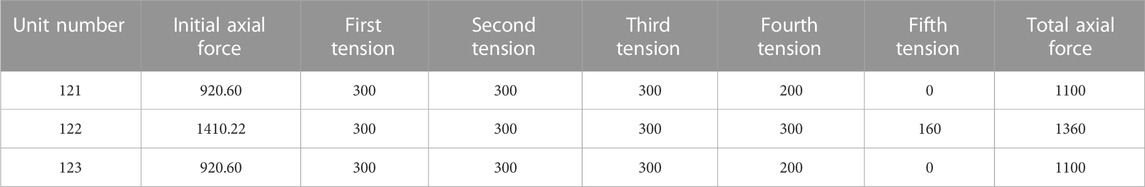
TABLE 5. Tensioning process during replacement of short booms at mid-span using the three-point method (KN).
In the case of replacing the short booms with the three-point method, the main cable node connecting the No. 122 boom experienced a downward displacement of −2.78 mm (Figure 10A). The maximum vertical displacements of the main cable nodes occurred at the No. 121 and No. 123 booms, both measuring −7 mm. Besides, the main beams in the main span underwent an upward displacement, resulting in a slight change in their geometric shape after tensioning (Figure 10B). The vertical displacements of the upper main beam nodes at the No. 121–123 booms were 0.42 mm, 0.35 mm, and 0.42 mm, respectively. These displacements indicate an increase in upward displacement compared to the one-point method of boom replacement. This indicates the replacement of short booms within the three-point method can introduce a certain level of disturbance to the main beams in the main span.
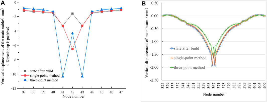
FIGURE 10. (A) Vertical displacement variation of the main cable node when the mid-span and short booms are tensioned by the three-point method. (B). Vertical displacement of the main beam on the upper floor when the mid-span and short booms are tensioned by the three-point method.
In the case of replacing the medium booms (No. 92, 93 and 94 at side span) with the three-point method, the axial forces during the uniform tensioning of the temporary booms are shown in Table 6. At the end of tensioning, the total axial force on the No. 93 temporary boom amounted to 1480 KN. This value is 438 KN lower compared to the single-point method, resulting in a force transmission efficiency of 93.95%. This efficiency is 21.47% higher than that achieved with the single-point method. These findings indicate that the three-point method offers certain advantages in reducing the axial force and improving the force transmission efficiency of the temporary boom when compared to the single-point method.
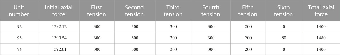
TABLE 6. Three-point tensioning of temporary booms with medium booms in side span (KN).
In the case of medium boom replacement with the three-point method, the main cable nodes at the three temporary booms experienced downward movements as shown in Figure 11A. Specifically, the main cable node at No. 93 exhibited the largest downward displacement of −43.7 mm, which is 0.02 mm less than that in the single-point method. The vertical displacement of the main cable nodes at No. 92 and No. 94 booms was −34.13 mm and −41.28 mm respectively. Generally, the affected range of the main cable nodes is expanded when compared to the single-point method. The vertical displacement of the upper main beam is shown in Figure 11B. An abrupt change in displacement occurred at the location of the replaced boom, resulting in an upward displacement of 0.53 mm. The main beams in the main span exhibited a complete upward movement, accompanied by significant variations in geometric shape. Moreover, a maximum upward displacement of 1.51 mm occurred at the main beam at the mid-span. In comparison, the single-point method yielded a displacement of 0.45 mm at the location of the abrupt change and a displacement of 0.72 mm at the main beam of the mid-span. These observations suggest that the three-point method has a greater impact on the vertical displacement and geometric shape of the main beam compared to the single-point method. Neither of the two replacement methods has affected the geometric shape of the main beam at the east side span.
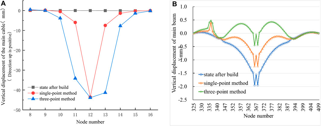
FIGURE 11. (A) Vertical displacement variation of main cable nodes when side-span medium booms are tensioned by the three-point method. (B). Vertical displacement of the main beam on the upper floor.
The force transmission efficiency of the three-point method is shown in Table 7. It is observed that the force transmission efficiency of a single temporary boom gradually decreased as the boom length increased. The transmission efficiencies of booms with lengths of 12.56 m and 15.71 m exceeded 98%, while booms with lengths below 50 m maintained a force transmission efficiency of over 90%. Therefore, the three-point method demonstrates high applicability for booms ranging from 10 m to 50 m in length. Based on these findings, booms within the range of 10–50 m on the sea crossing suspension bridge can be defined as medium booms. Furthermore, the definition of a medium boom can also be determined by considering the ratio of boom length to the rise of the main span. A boom with a ratio of boom length to rise of the main span that falls between 1 and 4.5 times the rise-span ratio can be classified as a medium boom. As well as booms with lengths exceeding 50 m and a ratio of boom length to rise of the main span exceeding 4.5 times the rise-span ratio are designated as long booms.

TABLE 7. Force transmission efficiency of the side-span boom using the three-point method.
In the case of replacing the long booms in the main span (No. 101, 102 and 103 boom close to the west bridge tower) using the three-point method, the axial force during the uniform tensioning of the temporary booms is shown in Table 8. At the end of tensioning, the total axial force on the No. 102 temporary boom was 1535 KN, which is 668 KN lower than that in the single-point method. Furthermore, the transmission efficiency is 90.62%, 27.48% higher compared to the single-point method. These results indicate that the three-point method offers advantages in reducing the axial force and enhancing the force transmission efficiency of the temporary boom, in contrast to the single-point method.
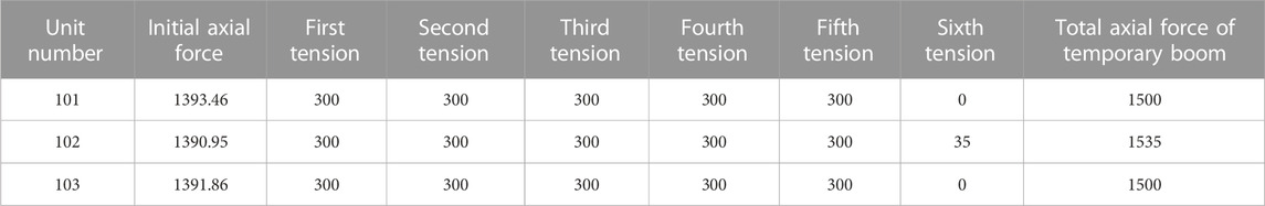
TABLE 8. Axial force change of temporary boom in replacement of long boom at main span using the three-point method (KN).
According to the vertical displacement of the main cable nodes (Figure 12A), the main cable nodes at No. 101–103 booms experienced significant downward displacement during the replacement of long booms using the three-point method. Specifically, the main cable node at No. 102 boom exhibited the largest displacement, reaching −70 mm, which is consistent with the displacement observed in the single-point method. Additionally, the vertical displacements of the main cable nodes at No. 101 and No. 103 booms were −63.64 mm and −56.36 mm, respectively. In addition, the main cable nodes on both sides of the temporary booms also exhibited downward movement to some extent. The displacement at the main cable node of the No. 100 boom was −15.14 mm, while that of the node at the No. 104 boom was −9.74 mm, both of which are greater than the displacements observed in the single-point method. Compared with the single-point method, the affected range of the main cable node increased, but the displacement has minimal impact on the main cable nodes located far from the temporary booms.
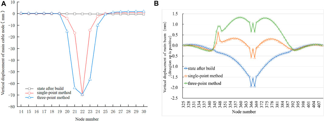
FIGURE 12. (A) Vertical displacement of the main cable. (B). Vertical displacement of the upper main beam.
The vertical displacement of the upper main beam nodes is shown in Figure 12B. It can be seen that the main beams in the main span underwent significant upward displacement and experienced notable changes in geometric shape after tensioning. The main beam at the mid-span exhibited the maximum upward displacement of 2.6 mm, which is 2.5 mm larger than that observed in the single-point method. Simultaneously, there was an abrupt change in vertical displacement at the position of the temporary booms. Specifically, the displacement of the main beam at the No. 102 boom was 1.26 mm, while that at the No. 101 and No. 103 booms were 1.25 mm and 1.05 mm, respectively. From these findings, it can be concluded that the three-point method has a greater effect on the displacement and geometric shape of the main beam compared to the single-point method. However, neither of the two replacement methods has an impact on the geometric shape of the main beams in the side span.
In the case of replacing the medium booms (No. 91–95 booms in side span) using the five-point method, the axial force during the uniform tensioning of the temporary booms is shown in Table 9. At the end of tensioning, the total axial force on the No. 93 temporary boom amounted to 1300 KN, which is 619 KN and 180 KN lower than that of the single-point method and the three-point method, respectively. Furthermore, the force transmission efficiency reached 106.96%, surpassing the three-point method by 10.01% and the single-point method by 34.48%. These results indicate that the interaction among multiple temporary booms in the five-point method significantly reduces the tension experienced by each individual temporary boom, thus reducing the requirements for the material properties and mechanical strength of the temporary booms.
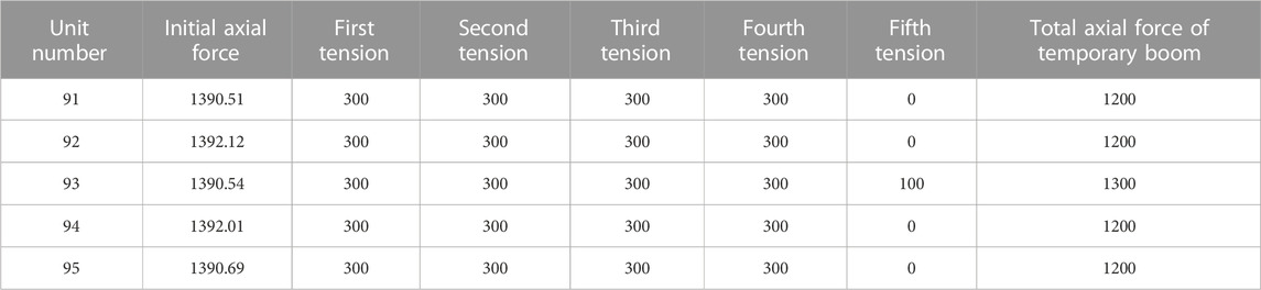
TABLE 9. Five-point method process of medium booms in side span (KN).
The vertical displacement of main cable nodes during the displacement of medium booms using the five-point method is shown in Figure 13A. It is found that the nodes at the temporary booms experienced significant downward movement. Specifically, the No.12 node exhibited the largest displacement of −43.44 mm, which is comparable to the displacements of −43.39 mm and −43.70 mm observed in the single-point method and the three-point method, respectively. It is evident that the three boom replacement methods yield similar effects on the vertical displacement of the main cable nodes at the replaced booms. Meanwhile, the first cable nodes immediately adjacent to both sides of the temporary booms also exhibited slight downward movement in the five-point method, signifying an expanded range of influence compared to the three-point method.
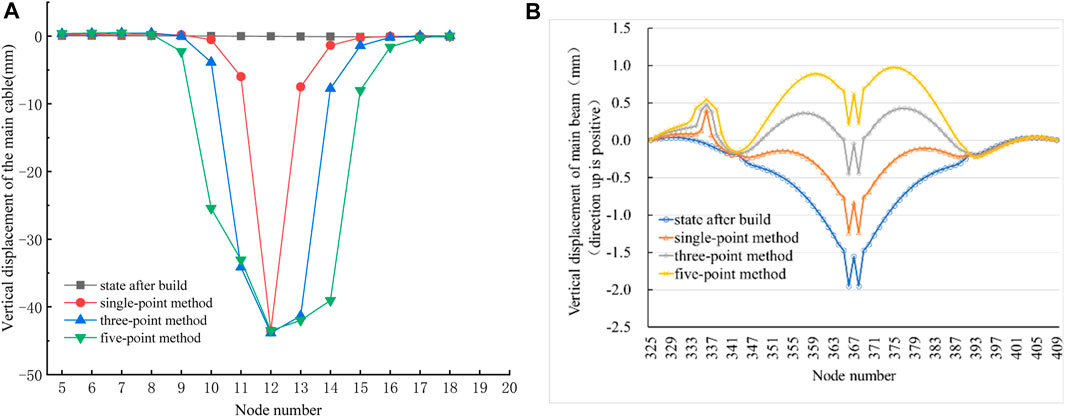
FIGURE 13. (A) Vertical displacement of main cable nodes at end of tensioning in replacement of medium boom in the side span with the five-point method. (B). Vertical displacement of the upper main beam.
The vertical displacement of the upper main beam is presented in Figure 13B. The main beam at the position of the temporary booms exhibited a sudden change in displacement. Specifically, the main beam at the No. 93 boom had a larger displacement of 0.60 mm. Concurrently, it is observed that the main beams in the main span collectively moved upward and underwent significant changes in geometric shape. Besides, the maximum displacement of main beams in the mid-span reached 2.16 mm. When compared to the single-point method, the displacement of the main beam at the No. 93 boom increased by 0.15 mm, and the displacement of the main beam in the mid-span increased by 1.46 mm. In contrast, when compared to the three-point method, the displacements at these two locations increased by 0.07 mm and 0.67 mm, respectively. These observations indicate that the five-point method has the most pronounced effect on the displacement and geometric shape of the main beams throughout the entire bridge when replacing medium booms in the side span. And none of the three replacement methods have any impact on the geometric shape of main beams at the east side span.
In summary, the five-point method demonstrates notable advantages in reducing the tension of temporary booms and significantly increasing the force transmission efficiency compared to the one-point method and the three-point method for replacing medium booms in the side span. However, it also introduces greater disturbance to the main cable and main beam, particularly to the main cable. Overall, the superiority of the five-point method in medium boom replacement is not clearly evident when compared to the three-point method.
The axial force during the uniform tensioning of the temporary booms in replacement of the long booms in the main span (No. 100–104 booms) using the five-point method is shown in Table 10. At the end of tensioning, the total axial force of No. 102 temporary boom was 1450 KN, and the force transmission efficiency was 95.93%, which is 32.79% higher than that in the single-point method and 5.32% higher than that in the three-point method. According to the vertical displacement of the main cable nodes shown in Figure 14A, the temporary booms in the five-point method replacement of long booms result in a significant downward displacement of the main cable nodes. Specifically, the main cable node at the No. 101 boom exhibited the largest vertical displacement of −70.85 mm, followed by the main cable node at the No. 102 boom with a displacement of −69.38 mm. Comparing the data with the single-point method and the three-point method, it is observed that the maximum displacement of the main cable nodes caused by the five-point method is the same as that of the single-point method and the three-point method. However, the notable difference lies in the location of the maximum displacement, which occurs at the main cable node of the No. 102 boom for both the single-point and three-point methods. In addition, the three replacement methods exhibited varying degrees of influence on the main cable nodes. Specifically, the single-point method had the smallest affected area, resulting in significant downward movement at only three main cable nodes. In contrast, the three-point method affected up to five main cable nodes with substantial downward displacement, with the three largest displacements occurring at the locations of the temporary booms. Similarly, the five-point method caused significant downward displacement in up to six main cable nodes, with the five largest displacements occurring at the positions of the temporary booms.
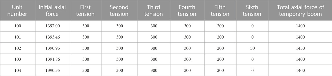
TABLE 10. Tensioning process in replacement of long boom in the main span by the five-point method (KN).
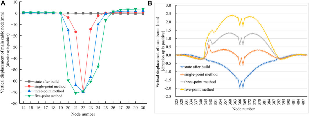
FIGURE 14. (A) Vertical displacement change of main cable node at end of tensioning in replacement of long boom in the main span by the five-point method. (B). Displacement change of the upper main beam.
The vertical displacement of the upper main beam is shown in Figure 14B. The five-point replacement method significantly altered the geometric shape of the main beams in the main span, resulting in a maximum displacement of 3.75 mm in the mid-span. This displacement exceeds that of the single-point method by 2.37 mm and the three-point method by 1.15 mm. It can be concluded that the five-point method has a notable influence on the vertical displacement and geometric shape of the main beams in the main span. However, none of the three boom replacement methods significantly impacted the beam at the east side span.
In general, the main advantage of the five-point method in replacing the long boom is the reduction in temporary boom tension by 753 KN compared to the single-point method and 85 KN compared to the three-point method. However, this advantage is not significantly greater than that of the three-point method. Therefore, when selecting the most suitable boom replacement method for actual bridge construction, a comprehensive evaluation is necessary.
As shown in Table 11, the changes in the axial force and force transmission efficiency of a single temporary boom with different replacement methods, it can be found that when replacing a short boom, the single-point method can achieve a force transmission efficiency of more than 90%. When replacing a medium-length boom, the maximum force transmission efficiency of a single temporary boom with the three-point method can also be maintained at more than 90%. When the five-point method replaces the long boom, the maximum force transmission efficiency of a single temporary boom can be greatly improved.
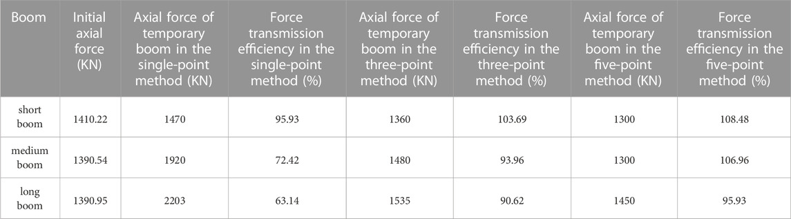
TABLE 11. Axial force and force transmission efficiency of a single temporary boom with different replacement methods.
In the paper, the adaptability of the nominal boom length and the boom replacement method is discussed according to numerical simulation analysis of the structural response during the boom replacement process. And the optimal replacement method of booms with different nominal lengths is determined. It can be seen that the single-point method is the optimal choice for replacing short booms, as it achieves a force transmission efficiency above 90% while reducing the axial force of the temporary boom and fully utilizing its function. Considering the bridge’s overall effect and construction complexity, the three-point method is most suitable for replacing medium booms, while the five-point method is more appropriate for long booms. These have practical guiding significance for the selection of suspender replacement method in the operation and maintenance of a sea crossing suspension bridge. The conclusions are also applicable to other suspension bridge. The nominal boom length of suspension bridge can be determined according to the method in this paper, then the optimal boom replacement method can be selected according to the nominal boom length. Which can simplify the theoretical analysis process of boom replacement, optimize the number of construction platform and equipment scale. At the same time, in the actual process of replacing booms, monitoring and controlling relevant parameters can ensure the quality of replacement, improve the efficiency of replacement.
The response of the bridge structure during boom replacement was analyzed using the single-point, three-point, and five-point methods. The process of boom replacement was simulated using the temporary boom method. Meanwhile, the performance of the three boom replacement methods in replacing short, medium, and long booms was extensively analyzed using a significant amount of data. The definition of the nominal boom length of suspension bridge is based on the correlation between the transmission efficiency of the temporary boom, the actual boom length and the main cable sag in the paper. Specifically, the nominal boom length and boom replacement method were quantitatively assessed based on the axial tensile force of temporary booms, the vertical displacement of the main beams and cables, and the change in the remaining axial force of booms. And the optimal replacement method for booms with different nominal lengths was determined. Simultaneously discovered, the force transmission efficiency of the temporary boom decreases as the boom length increases, with a larger rate of decrease observed for longer booms.
The above analysis can be widely applied to the operation, maintenance and management of the same type of suspension bridge. Conclusion in the paper can ensure the safety and reliability of bridge structures during operation, reduce maintenance costs in the later stages of operation, and enhance the safety protection ability of operating bridges, which has significant reference value.
The original contributions presented in the study are included in the article/Supplementary material, further inquiries can be directed to the corresponding author.
Conceptualization, YM; methodology, CC; software, QH; validation, YZ; investigation, YT; data curation, GL. All authors contributed to the article and approved the submitted version.
This research was funded by Scientific Research Project of the Educational Department of Liaoning Provincial (The Education Department of Liaoning Province, grant number-100920202019); Key Laboratory of Environment Controlled Aquaculture (Dalian Ocean University, grant number-202302).
The authors declare that the research was conducted in the absence of any commercial or financial relationships that could be construed as a potential conflict of interest.
All claims expressed in this article are solely those of the authors and do not necessarily represent those of their affiliated organizations, or those of the publisher, the editors and the reviewers. Any product that may be evaluated in this article, or claim that may be made by its manufacturer, is not guaranteed or endorsed by the publisher.
Alastair, A. S., and Colford, B. R. (2017). “Forth Road bridge-maintenance challenges [M],” in Advances in cable-supported bridges (New York: Taylor & Francis Group Logo).
Cao, F. A (2020). Analysis on construction technology and quality control of suspender replacement for tied arch bridge. Traffic Constr. Manag. (06), 138–139.
Dou, Y. (2020). A case study on the replacement of cable clips of A suspension bridge and Key technologies. Urban Roads, bridg. Flood Control (09), 131–134.
Fan, B., Wang, S., Chen, B., Chao, P-F., Sun, Q., et al. (2023). Robustness-based condition evaluation frameworkfor through tied-arch bridge. J. Perform. Constr. Facil. 37 (2), 06023001. doi:10.1061/jpcfev.cfeng-4048
Han, X. (2020). Research on the fracture safety of corroded suspenders of self-anchored suspension bridge [D]. Dalian University of Technology.
Huang, W., and Zhang, X. (2021). “Exploration of suspension bridge suspension rod replacement technology-based on the method of cable replacement without affecting the spatial position of the cable girder[A],” in Maintenance and management branch of China highway society. The 11th academic annual conference of maintenance and management branch of China highway society collection of essays.
Li, Y. (2021). Research on replacement method and bearing capacity of suspension bridges in service [D]. Chang’an University. doi:10.26976/dcnki.gchau.2021.000377
Liu, W., Tang, M., Xu, B., Shen, J. H., Wang, Z., and Wang, X. W. (2023). COAP/Pd-Catalyzed linear asymmetric allylic alkylation for optically active 3,3-disubstituted oxindole derivatives with a four-carbon amino side chain. World bridg. 51 (2), 104–108. doi:10.1021/acs.orglett.2c03902
Radojevic, D., Kirkwood, K. F., and Matson, D. D. A. (2019). A tale of twobridges: extending the lifetimes of the Lions gate and angus L. Macdonald suspension bridges. Struct. Eng. Int. 29 (4), 527–532. doi:10.1080/10168664.2019.1624142
Süleyman, A., Ebru, K. O., Ahmet, C. A., Günaydin, M., and Rahwan, B. R. (2023). Investigation of the structural behaviors of Bosphorus suspension bridge with vertical hangers replaced by inclined hangers. Alex. Eng. J. 65, 75–102. doi:10.1016/j.aej.2022.10.041
Sun, H. (2014). Typical diseases and replacement technology of suspenders of jiangyin bridge. Sci. Technol. Innov. Appl. (31), 70–71.
Wang, J., Wang, X., and Yang, C. (2015). Construction and monitoring of Shantou Bay bridge test suspender replacement project. Highw. Auto. Transp. (6), 172–177.
Xu, T. (2020). Corrosion fatigue analysis and structural improvement of arch bridge suspenders [D]. Harbin Institute of Technology.
Yang, H., and Lu, W. (2022). Key technologies for arch bridge suspender replacement under heavy load protection requirements [J]. Zhongwai Highw. 42 (03). doi:10.14048/j.issn.1671-2579.2022.03.022
Yu, Z. H., Zhang, D., Zhang, Y., et al. (2019). Suspender replacement technology and stress state simulation analysis of long-span suspension bridges. Zhongwai Highw. 39 (02), 82–88. doi:10.14048/j.issn.1671-2579.2019.02.018
Yuan, A., Yang, T., Xia, Y., et al. (2021). Replacement technology of long suspenders of runyang suspension bridge. China Highw. J. 34 (02), 289–297. doi:10.19721/j.cnki.1001-7372.2021.02.017
Keywords: suspension bridge, replacement method, boom length, force transmission efficiency, adaptability analysis
Citation: Mu Y, Hu Q, Chen C, Tan Y, Zheng Y and Liang G (2023) Study on the adaptability and optimization of boom replacement methods for suspension bridges. Front. Mater. 10:1229930. doi: 10.3389/fmats.2023.1229930
Received: 27 May 2023; Accepted: 31 July 2023;
Published: 10 August 2023.
Edited by:
Yunlai Zhou, Xi’an Jiaotong University, ChinaReviewed by:
Chuncheng Liu, Northeast Electric Power University, ChinaCopyright © 2023 Mu, Hu, Chen, Tan, Zheng and Liang. This is an open-access article distributed under the terms of the Creative Commons Attribution License (CC BY). The use, distribution or reproduction in other forums is permitted, provided the original author(s) and the copyright owner(s) are credited and that the original publication in this journal is cited, in accordance with accepted academic practice. No use, distribution or reproduction is permitted which does not comply with these terms.
*Correspondence: Changping Chen, Y2NwQGRsb3UuZWR1LmNu
Disclaimer: All claims expressed in this article are solely those of the authors and do not necessarily represent those of their affiliated organizations, or those of the publisher, the editors and the reviewers. Any product that may be evaluated in this article or claim that may be made by its manufacturer is not guaranteed or endorsed by the publisher.
Research integrity at Frontiers
Learn more about the work of our research integrity team to safeguard the quality of each article we publish.