 Nitish Kaushik
 Sanjay Kumar Jha
 Ravi Shankar Anand2*
95% of researchers rate our articles as excellent or good
Learn more about the work of our research integrity team to safeguard the quality of each article we publish.
Find out more
ORIGINAL RESEARCH article
Front. Mater. , 29 June 2023
Sec. Polymeric and Composite Materials
Volume 10 - 2023 | https://doi.org/10.3389/fmats.2023.1147882
This article is part of the Research Topic Fiber-Reinforced Composites: Design, Characterization, Analysis, and Application View all 6 articles
Recently, most of the conventional (industrial) materials such as steel, aluminum, and copper are being replaced by composite materials. Among the various composite materials, CFRP material is one of the most popular materials in many industries due to its excellent mechanical properties like-high strength, high modulus, compressive strength, etc. However, the micro hole in micro EDM drilling in the CFRP composite material is challenging due to fiber orientation, uneven distribution of conducting fiber, and delamination affecting the material removal rate (MRR) and micro hole quality performance. The objective of the article is to optimize the process parameters for optimum hole quality in the micro EDM drilling of CFRP composites. For this purpose, response surface methodology is applied to investigate the effect of the input process parameters which are voltage, capacitance, and tool rotation speed on material removal rate, roundness error, and tapper of the micro-hole. The experiments have been conducted according to the box behnken design of experiments. Regression equations, and response surfaces are developed. Optimum responses are determined by the desirability function approach. The experimental investigation shows that capacitance is the highly significant factor among the input process parameters affecting hole quality output responses such as material removal rate, roundness error, and tapper. The MRR increases with increasing the capacitance and tool rotation speed initially but its value decreases on further increasing the capacitance at a particular voltage. Roundness error and the tapper initially decrease on increasing capacitance and tool rotation speed then increases. The optimum material removal rate and hole quality are obtained in a range of 150–250 nF capacitance, and 1400–1600 rpm tool rotation speed, at 100 voltage.
Recently, the miniaturization of industrial products has increased our living standards. Microchips, sensors, laptops, and cell phone micro-components are impressive examples of miniaturization (Takahata and Gianchandani, 2002). The Micro features-based micro product increases the efficiency of the system due to its small size and lightweight. The micro-holes are one of the important micro-features of micro products of many industries like electronics, aerospace, environment, biomedical, automotive, etc (Kumar et al., 2020). Most of the micro products having micro holes are manufactured with composite material due to its excellent mechanical properties such as high strength and lightweight. For example, printed circuit boards and gas turbine blades a remanufactured by CFRP composites having micro holes (Masuzawa, 2000; Wang and Han, 2014).
Micro holes are produced by various manufacturing methods, including micro-electrical discharge (µEDM), electron beam, laser beam micromachining, ultrasonic micromachining, and mechanical micro-drilling processes (Eckart, 2010; Sivaprakasam et al., 2021). Among the various micro-drilling processes, µEDM drilling process produces micro holes by electron discharge method in the electrically conductive materials. During the material removal process, the tool and workpiece are not in contact, and the material of the workpiece melts and evaporates due to the high temperature produced by electron discharge process. The material removal process is affected by electrode voltage, capacitance, tool rotation, and pulse rate rather than the mechanical properties of the workpiece such as tensile strength, hardness, toughness, chatter, and vibration (Rajurkar et al., 2006; Teimouri and Baseri, 2012a; Teimouri and Baseri, 2012b; Teimouri and Baseri, 2013; Ji et al., 2014). The µEDM process has potential to produce micro holes with high dimensional accuracy and repeatability (Satyarthi and Pandey, 2013). However, downscaling of the tool diameter of the electrode shows significant differences of the material removal mechanism of the µEDM drilling process from macro-EDM processes (Masuzawa, 2000; Wang and Han, 2014). The electrode diameter of the macro-EDM is larger than the µEDM which mainly changes the discharge of the pulse affecting the energy density on the hole surface. In the macro-EDM, discharge pulses are generated for a longer time, and plasma is spread over the large surface area of the macro hole. Workpiece material is removed from the large surface area and the material is considered as homogenous. The amount of debris can be ignored due to the large diameter. On the other hand, in the µEDM process, the discharge pulses are produced for a short time and the plasma spread over a particular grain and material cannot be considered as homogeneous material. The effect of debris on the hole quality cannot be ignored in the µEDM. The effect of debris is amplified in the composite material due to fiber orientation (Liu et al., 2016).
Most of the research works that have been carried out in the micro EDM are related to metallic materials (Eckart, 2010). Kadirvel et al. (Kadirvel et al., 2013) conducted experiments on the machining of EN24 die steel with different electrodes such as tungsten, copper, copper tungsten, and silver tungsten using µEDM and found that the material removal rate (MRR) depends on the internal electrode gap and overcut is higher at maximum MRR. Kuriakose et al. (Kuriakose et al., 2020) explained that tool rotation speed is one of the important factors in µEDM drilling of metallic glass. The tool rotation speeds affect the edge, taper angle, deviation, and overcut significantly. Micro EDM drilling in the CFRP composite material is challenging due to the micro range of tool diameter, anisotropic mechanical properties, fiber orientation, uneven distribution of conducting fiber, and delamination (Lau et al., 1990; Teicher et al., 2013; Park et al., 2015; Ahmad, 2016). Teicher et al. (Teicher et al., 2013) observed that low pulse energies produce a low material removal rate but a low pulse reduces tool wear and increased surface quality in the micro EDM drilling of the CFRP. Kumar et al. (Kumar et al., 2018) investigated the maximum MRR in µEDM drilling of CFRP composite with influence of input process parameters using Taguchi design of experiments and analysis of variance (ANOVA) and determined the maximum MRR at the high voltage and capacitance. Dutta et al. (Dutta et al., 2020) applied Grey relational analysis to optimize the micro-hole quality in terms of hole dilation in the CFRP material and observed that voltage is one of the input factors affecting the hole quality.
After reviewing the literature, it can be concluded that a few articles describe the effect of the input process parameter on the micro-hole quality in the micro EDM drilling of composite materials and the optimization of more than one input parameter simultaneously is also rear in the literature. Therefore, it is necessary to carry out research to analyze the effect of the input process parameters on the material removal rate (MRR) and hole quality in the micro EDM drilling of the CFRP composite using statistical modeling techniques. RSM modeling method provides a way to establish the relationship between more than one parameter simultaneously and optimization can be done by the desirability function approach. Thus, the objective of the article is to investigate the optimum hole quality and MRR to the input process parameter including capacitance, voltage, and tool rotation speed using RSM in the micro EDM drilling of CFRP composite. Design of experiment is based on the Box-Behnken method having three factors and three levels with three center points. The adequacy of the model is evaluated by ANOVA analysis and response surfaces are developed to show the trend of hole quality properties to the input parameters. The optimum hole quality and MRR are predicted by the desirability function approach. The predicted results are also compared with experimental results.
For requirements, the workpiece material is CFRP composite. The fiber volume is approx. 55% and the rest is covered with the help of epoxy material as shown in Figure 1A. The epoxy is used as a matrix in the CFRP composite material which binds the reinforced fiber together. The epoxy is selected because it has high adhesive and wear resistance that increases the flexibility and durability of the CFRP (Uthaman et al., 2020a). Brinell hardness of the CFRP is 100.05 BHN (Ghani et al., 2019). The dimensions of the workpiece are 25 mm × 25 mm × 0.6 mm. To uncover the carbon fiber layer for better conductivity, the top surface of the CFRP was rubbed using sandpaper.
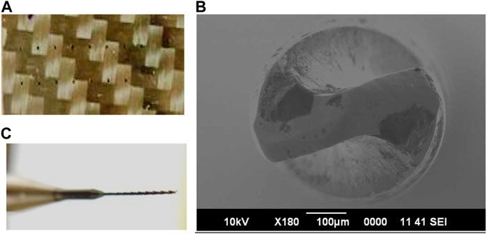
FIGURE 1. (A) CFRP Workpiece material (B) Tool and (C) SEM image of drill bit.
A solid flute Tungsten Carbide drill bit is used as a tool electrode because it has high hardness, melting point, and heat-resistant capacity (Uthaman et al., 2020b). The dimension of the tool electrode is 5 mm of drilling length with 250 microns diameter as shown in Figure 1B, C respectively. The Experiments have been performed on CNC EDM Micro Machining Centre (Mikrotools DT-110) as shown in Figures 2A, B. Position feedback scales have a resolution of 0.1 μm and working table dimensions are X-200 mm, Y-100 mm, and Z-100 mm. The spindle speed range is up to 3000 RPM. The micro drilled hole quality is evaluated by roundness error, tapper angle, and material removal rate with the influence of input process parameters that are voltage, capacitance, and rotation speed of tool electrode. Experiments were conducted using the Box-Behnken method of design of experiments of response surface methodology (Anand and Patra, 2018). Box-Behnken designs are used to generate higher-order response surfaces required fewer experimental run than a normal factorial experimental runs. Box-Behnken designs are independent quadratic designs that do not contain an embedded factorial or fractional factorial design. Design treatments are at the midpoint of the edge of the process space and the center requiring three center points. Three factors and three levels have been used as given in Table 1. The levels of input parameters are selected on the basis of the range of CNC EDM Micro Machining Centre and previous work also shows that the level of the parameters frequently used in micro EDM drilling of CFRP composite as mentioned by Kumar et al. (Kumar et al., 2018).
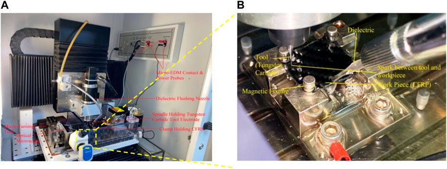
FIGURE 2. (A) Experimental setup and (B) tool and workpiece assembly closed view.
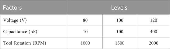
TABLE 1. Design of experiments.
In the Micro EDM drilling of the CFRP, the micro hole quality is not only depend on the process parameters but also depend on the material properties such as orientation of carbon fibre. Material removal process is different at different fiber orientation which cannot be controlled. In the present work, the fibre orientation is not considered and the deviation of the experimental results is neglected by taking average value of the hole quality of the three times experimental results of the same input process parameters with fresh tools and average values are used as output responses. The MRR, roundness error, and tapper of the hole are determined by taking the difference of the average value of the top and bottom circumference of the micro holes. The average value of the top and bottom circumference is calculated by an average value of the inner and outer circle circumference of micro holes as shown in Figure 3A.
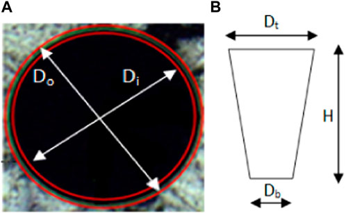
FIGURE 3. Hole quality parameters (A) roundness error (B) tapper.
The tapper parameter is shown in Figure 3B. The MRR, roundness error, tapper angle, and are calculated using Eqs. 1 2, 3 respectively.
To establish a relation between input factor and output response, response surface methodology has been applied. Second-order polynomials which are a non-linear functions having linear, interacting, and power terms are used in the modeling of several manufacturing processes as given by Eq. 4 (Uthaman et al., 2020a).
Where
Experimental results of material removal rate (MRR), roundness error, and tapper for all combinations of voltage, capacitance, and tool rotation are given in Table 2. The influence of the input parameters, i.e., tool rotation speed, voltage, and capacitance on the material removal rate, roundness error, and tapper have been evaluated through analysis of variance (ANOVA). A 95% confidence interval with a 5% significance level is used for the adequacy of the quadratic statistical model. ANOVA for MRR, roundness error, and tapper are shown in Table 3 to Table 5, respectively. Table 3 shows ANOVA for the material removal rate (MRR). The quadratic model is significant with 97.39% of the coefficient of determination. In the quadratic model, a square of capacitance is highly significant. Moreover, the square of tool rotation speed is also contributing to the model. However, the capacitance, tool rotation speed, and voltage are insignificant and their interacting factors are also insignificant. Table 4 describes the ANOVA of roundness error which is also significant with a 96.44% coefficient of determination. In the quadratic model, a square of capacitance has a major contribution and it is a highly significant factor. The interaction of capacitance, and voltage, and square of voltage are significant factors. Capacitance and voltage are also significant factors. Tool rotation speed, the interaction of tool rotation speed and capacitance, and voltage are insignificant; Table 5 shows the ANOVA of the tapper. The quadratic model confidence interval is significant with a 97.81% coefficient of determination (R2). In the quadratic model, the effect of the square of capacitance is highly significant. Tool rotation speed, voltage, and capacitance are insignificant.
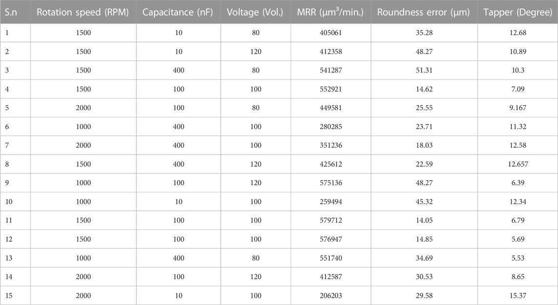
TABLE 2. Experimental results for roundness error, MRR, and tapper.
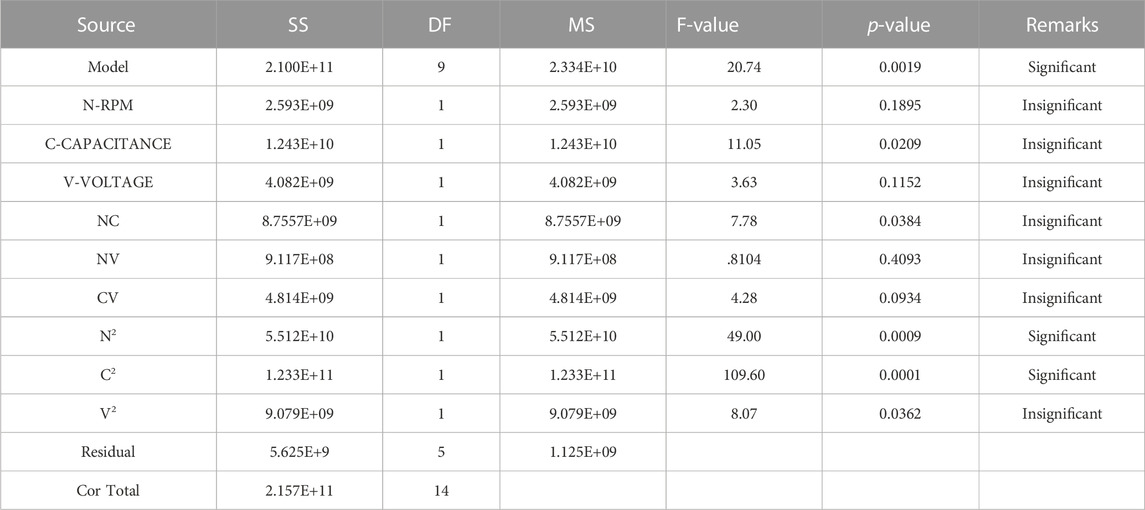
TABLE 3. ANOVA analysis of Material Removal Rate (MRR).
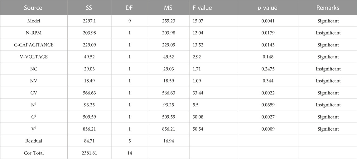
TABLE 4. ANOVA analysis of Roundness Error.
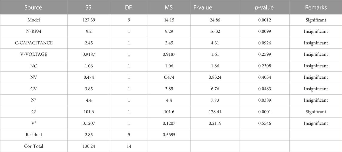
TABLE 5. ANOVA analysis of Tapper.
Based on the ANOVA, the mathematical regression equations of the MRR, roundness, and tapper are developed as given in Eq. 5–7.
The coefficient of determination of MRR, roundness error, and tapper are above the 95% confidence interval. The regression equations are also validated with experimental results. Figure 4 shows good agreement between the predicted and experimental tapper.
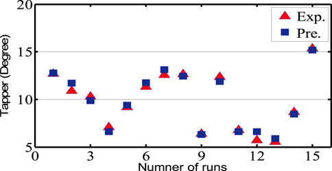
FIGURE 4. Comparison of experimental and predicted results of tapper.
Response Surfaces of MRR, roundness error, and tapper are determined using regression equations. The capacitance and tool rotation speed are considered as input variables on two horizontal axis and vertical axis present the output response at a constant voltage. Figure 5 show the response surface of the MRR at three constant voltage. The response surface of the MRR is parabolic curvature with capacitance and tool rotation speed at three different constant voltages. The MRR increases with increasing the capacitance but MRR decreases after the mid-range value of the capacitance. A similar trend is also observed with the tool rotation speed. The response surfaces also show that the effect of the capacitance on the MRR is more than the tool rotation speed because the slope of the parabolic curve of capacitance is more than the tool rotation speed due to its large contribution in ANOVA model as discussed in the previous section. Figure 6 shows the trend of the roundness error to the capacitance and tool rotation speed at a constant voltage.
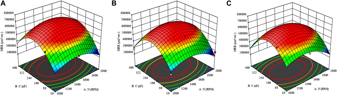
FIGURE 5. Effect of Capacitance and tool rotation speed on MRR at (A) 80V (B) 100V (C) 120V.
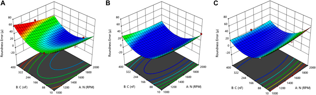
FIGURE 6. Effect of Capacitance and tool rotation speed on Roundness Error at (A) 80V (B) 100V (C) 120V.
Roundness error decreases with increasing the capacitance value up to the mid-value. On further increasing the capacitance, the roundness error increases at a constant voltage but the magnitude of the roundness error increases on decreasing the voltage as shown in Figures 6A, B, and C. Minor effect of tool rotation speed is observed on the roundness error at all three condition of the voltage. The minimum roundness error is obtained in the range of the 150–250 nF capacitance and 100–120 V voltage. Capacitance and voltage are the two most affecting parameters in case of roundness error. Figure 7 describes the trends of the tapper to the capacitance and tool rotation speed at different voltages. The trend of the taper is almost similar to the roundness error. On increasing the capacitance, the taper decreases sharply up to a middle range of capacitance and then increases on further increasing the capacitance at a constant voltage. A little variation is observed in the tapper on the increasing tool rotation speed. It can be concluded from the above analysis that capacitance is a highly significant factor affecting the MRR, roundness error, and tapper. The optimum responses are determined using the desirability function approach. Multi-objective optimization is applied in this analysis and the goal of the optimization is to minimize the roundness error and tapper, and maximize the MRR. The range of input process parameters are selected for the optimization. The optimum range of the output response is obtained in the mid-range of the capacitance. The optimum value is obtained between the 150–250 nF capacitance and 1400–1600 rpm as given in Table 6. Similar results of the MRR were obtained by Kumar et al. (Kumar et al., 2018).
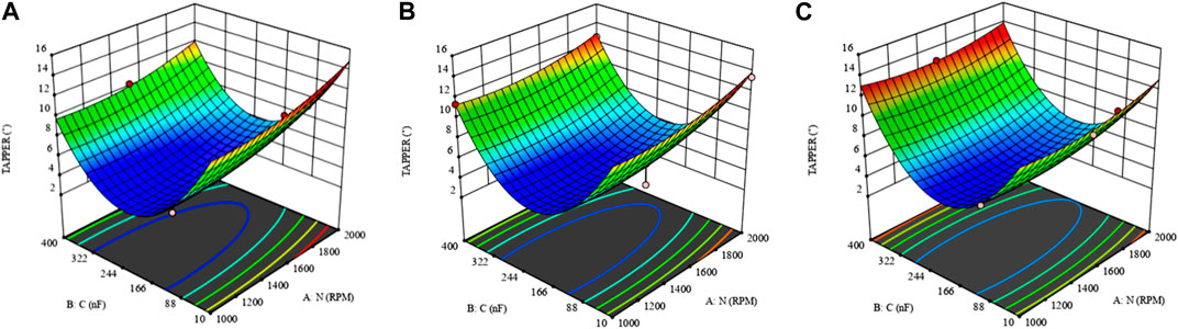
FIGURE 7. Effect of Capacitance and tool rotation speed on Tapper at (A) 80V (B) 100V (C) 120V.

TABLE 6. Optimum conditions of input factors for responses.
To determine the optimization range with respect to most significant factor, i.e., capacitance, the trade-off graph is developed. Figure 8 shows the maximum MRR and minimum tapper and roundness error trend with respect to capicatance at constant 1500 RPM, and 100 Voltage to describe the trade-off properties of response simultaneously. It also explain that the maximum MRR and minimum Tapper and RE are obtained between 100nF and 350 nF.
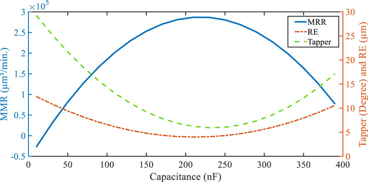
FIGURE 8. Trade -Off graph of MRR, Tapper and Roundness Error to the Capacitance.
It may be due to the heat generation effect of the capacitance and delaminating of CFRP composite (Hegde et al., 2019). The hole diameter is 250 microns which is quite small and it is comparable to the cutting tool edge thickness of conventional and non-conventional machining process. Therefore, it is difficult to find out the cross sectional image of micro hole having tapper, and roundness error. Figures 9A, B show the microscopic image of top and bottom surface of the minimum condition of roundness error (RE) at mid-value of capacitance 100 nF. Figure 10A, B shows the microscopic image of top and bottom surface of maximum condition of roundness error (RE) at high value of capacitance 400nf at 100V and 1500 rpm. The difference in measurement shows the roundness error (RE) and tapper in the micro hole. Figure 11A shows SEM image at minimum condition of roundness error (RE) showing no sign of debris and pockmarks. Figure 11B shows the image at high value of capacitance indicating the delamination, debris and pockmarks.
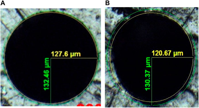
FIGURE 9. (A) Microscopic image of minimum roundness error (A) top side and, (B) bottom side.
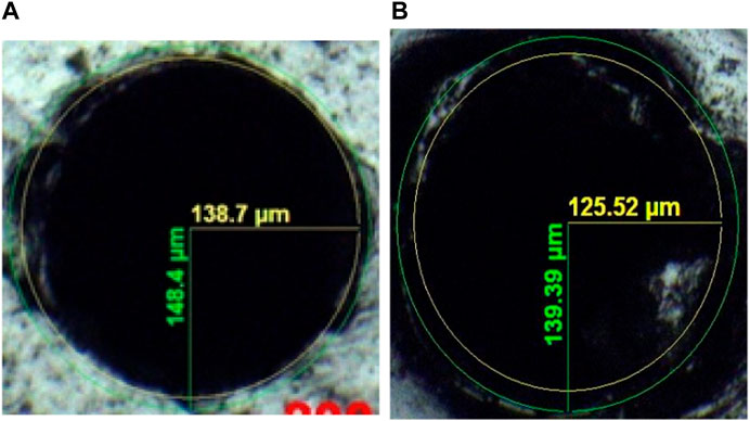
FIGURE 10. (A) Microscopic image of maximum roundness error (A) top side and, (B) bottom side.
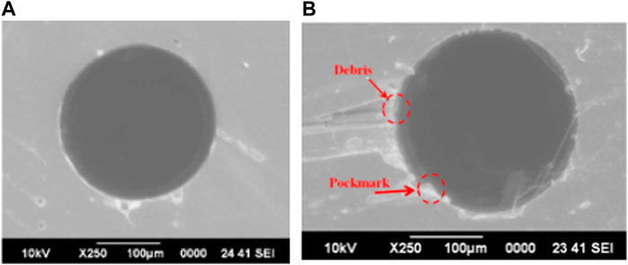
FIGURE 11. (A) SEM image of hole at minimum RE condition (B) SEM image of maximum RE condition showing delamination effect.
As can be seen in Figure 11B, different irregularities of micro-holes were observed at different locations of the hole due to the high discharge energy produced by high capacitance, and craters are formed around micro-drill holes. A large amount of wear-out electrode material combined with debris results in a large number of pockmarks. Table 7 shows that present work is also compared with previous existing work. Three studies have been found in the micro EDM drilling of the CFRP composite material. No literature was found on the micro EDM drilling of CFRP to predict the hole quality. Present work shows that minimum roundness error is 6 µm approximately in the range of 150–250 nF capacitance and 80 to 120 voltage at 1500 rpm obtained by desirability function approach. It can be concluded from the above analysis that capacitance is an important input process parameter affecting the micro-hole quality and MRR significantly.
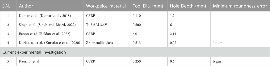
TABLE 7. Comparison of results with published literature.
The following conclusions were obtained based on the findings of the investigation under consideration in this study that can be used to predict the optimum hole quality of the industrial components.
• The Quadratic model of the response surfaces methodology successfully represents the trend of the MRR and roundness error.
• Capacitance is the most significant input process parameter that affects the MRR, roundness error, and tapper.
• An increment in roundness error, tapper, and decrement in MRR was observed with the increment in the capacitance and RPM shows a minor effect at a constant voltage.
• The minimum and maximum roundness error (RE) of the micro-hole at mid-value 100 nF and high-value capacitance 400 nF at 100 V and 1500 rpm, respectively.
• The optimum value of MRR and hole quality are obtained at 150–250 nF and 1400–1600 rpm at a 100V voltage.
• Delamination, debris, and irregularities around the micro-hole increases the roundness error at 400 nF capacitance.
The original contributions presented in the study are included in the article/supplementary material, further inquiries can be directed to the corresponding author.
NK investigation, writing—original draft, SJ conceptualization, writing—review and editing, RA Data curation, supervision. All authors contributed to the article and approved the submitted version.
I want to thank all the co-authors for their expertise and assistance throughout all aspects of our study and for their help in writing the manuscript.
The authors declare that the research was conducted in the absence of any commercial or financial relationships that could be construed as a potential conflict of interest.
The reviewer KK declared a shared affiliation with the authors to the handling editor at the time of review.
All claims expressed in this article are solely those of the authors and do not necessarily represent those of their affiliated organizations, or those of the publisher, the editors and the reviewers. Any product that may be evaluated in this article, or claim that may be made by its manufacturer, is not guaranteed or endorsed by the publisher.
Ahmad, J. Y. S. (2016). Hole quality and damage in drilling carbon/epoxy composites by electrical dischargemachining. Mater. Manuf. Process. 31 (7), 941–950. doi:10.1080/10426914.2015.1048368
Anand, R. S., and Patra, K. (2018). Cutting force and hole quality analysis in micro-drilling of CFRP. Mater. Manuf. Process. 33 (12), 1369–1377. doi:10.1080/10426914.2017.1401715
Assarzadeh, S., and Ghoreish, M. (2013). Statistical modeling and optimization of process parameters in electro-discharge machining of cobalt-bonded tungsten carbide composite (WC/6%Co). Procedia CIRP 6 (6), 463–468. doi:10.1016/j.procir.2013.03.099
Dutta, H., Debnath, K., and &Sarma, D. K. (2020). Multi-objective optimization of hole dilation at inlet and outlet during machining of CFRP by μEDM using assisting-electrode and rotating tool. Int. J. AdvManufTechnol 110, 2305–2322. doi:10.1007/s00170-020-05987-3
Eckart, U. M. (2010). Chapter 3, micro-EDM in micro and nano technologies, micro-manufacturing engineering and tech. Boston: William Andrew Publishing, 39–58.
Ghani, A. F., Yaakob, M. Y., Salim, M. N., and Mahmud, J. (2019). Hardness Assessment of Hybrid composite CFRP and GFRP. Int. J. Recent Technol. Eng. (IJRTE) ISSN 8, 2277–3878. 1S5.
Harane, P. P., Sharma, P. O., and Unune, D. R. (2023). Optimization of electric discharge drilling of Waspaloy using desirability function analysis. Mater. Today Proc. 72, 1342–1346. doi:10.1016/j.matpr.2022.09.328
Hegde, S., Shennoy, B. S., and Chethan, K. N. (2019). Review on carbon fiber reinforced polymer (CFRP) and their mechanical performance. Mater. Today Proc. 19, 658–662. doi:10.1016/j.matpr.2019.07.749
Ji, R., Liu, Y., Diao, R., Zhang, Y., Wang, F., Cai, B., et al. (2014). Experimental research on electrical discharge machining characteristics of engineering ceramics with different electrical resistivities. Int. J. Adv. Manuf. Technol. 75 (9-12), 1743–1750. doi:10.1007/s00170-014-6258-9
Kadirvel, A., Hariharan, P., and Gowri, S. (2013). Experimental investigation on the electrode specific performance in micro-EDM of die-steel. Mater. Manuf. Process. 28 (4), 390–396. doi:10.1080/10426914.2013.763959
Kumar, D., Singh, N. K., and Bajpai, V. K. (2020). Recent trends, opportunities and other aspects of micro-EDM for advanced manufacturing: A comprehensive review. J. Braz. Soc. Mech. Sci. Eng. 42, 222–226. doi:10.1007/s40430-020-02296-4
Kumar, R., Agrawal, P. K., and Singh, I. (2018). Fabrication of micro holes in CFRP laminates using EDM. J. Manuf. Process 3, 859–866. doi:10.1016/j.jmapro.2018.01.011
Kuriakose, S., Patowari, P. K., and Bhatt, J. (2020). Effect of micro-EDM machining parameters on the accuracy of micro hole drilling in Zr-based metallic glass. Eng. Res. Express 2, 015001. doi:10.1088/2631-8695/ab5c72
Lau, W. S., Wang, M., and Lee, W. B. (1990). Electrical discharge machining of carbon fibre composite materials. Int. J. Mach. Tools Manuf. 30 (2), 297–308. doi:10.1016/0890-6955(90)90138-9
Liu, Q., Zhang, Q., Zhang, M., and Zhang, J. (2016). Review of size effects in micro electrical discharge machining. Precis. Eng. 44, 29–40. doi:10.1016/j.precisioneng.2016.01.006
Masuzawa, T. (2000). State of the art of micromachining. CIRP Ann. ManufTechnol 49 (2), 473–488. doi:10.1016/S0007-8506(07)63451-9
Park, S. H., Kim, G., Lee, W., Min, B. K., Lee, S. W., and Kim, T. G. (2015). “Micro hole machining on precision CFRP components using electrical discharging machining,” in Paper presented at 20th International Conference on Composite Materials, Copenhagen, Denmark, July 2015 (Aalborg, Denmark: Aalborg University, Lyngby, Denmark: Technical University of Denmark).
Rajurkar, K. P., Levy, G., Malshe, A., Sundaram, M. M., McGeough, J., Hu, X., et al. (2006). Micro and nano machining by electro-physical and chemical processes. CIRP Ann. - Manuf. Technol. 55 (2), 643–666. doi:10.1016/j.cirp.2006.10.002
Roldan, J. L., Bañon, F., Valerga, A. P., and Fernandez, V. S. R. (2022). Design and analysis of CFRP drilling by electrical discharge machining. Polymers 14, 1340. doi:10.3390/polym14071340
Satyarthi, M. K., and Pandey, P. M. (2013). Modeling of material removal rate in electric discharge grinding process. Int. J. Mach. Tools Manuf. 74, 65–73. doi:10.1016/j.ijmachtools.2013.07.008
Singh, N., and Bharti, P. S. (2022). Experimental investigations and parametric optimization during micro-EDM drilling of Ti-5.6Al3.6V using ABC algorithm. J. Engg. Res. doi:10.36909/jer.ICMET.17201
Sivaprakasam, P., Udaya, J., Prakash, P., Hariharan, P., and Gowri, S. (2021). Micro-electric discharge machining (Micro-EDM) of aluminium alloy and aluminium matrix composites - a review. Adv. Mater. Process. Technol. 8, 1699–1714. doi:10.1080/2374068X.2020.1865127
Takahata, K., and Gianchandani, Y. B. (2002). Batch mode micro-electro-discharge machining. J. Microelectro Mech. Syst. 11 (2), 102–110. doi:10.1109/84.993444
Teicher, U., Muller, S., Munzner, J., and &Nestler, A. (2013). Micro-EDM of carbon fibre-reinforced Plastics. Procedia CIRP 6, 320–325. doi:10.1016/j.procir.2013.03.092
Teimouri, R., and Baseri, H. (2012a). Effects of magnetic field and rotary tool on EDM performance. J. Manuf. Process. 3 (14), 316–322. doi:10.1016/j.jmapro.2012.04.002
Teimouri, R., and Baseri, H. (2013). Experimental study of rotary magnetic field-assisted dry EDM with ultrasonic vibration of workpiece. Int. J. Adv. Manuf. Technol. 67 (5-8), 1371–1384. doi:10.1007/s00170-012-4573-6
Teimouri, R., and Baseri, H. (2012b). Study of tool wear and overcut in EDM Process with rotary tool and magnetic field. Adv. Tribol. 2012, 1–8. doi:10.1155/2012/895918
Uthaman, A., Xian, G., Thomas, S., Wang, Y., Zheng, Q., and Liu, X. (2020a). Durability of an epoxy resin and its carbon fiber- reinforced polymer composite upon immersion in water, acidic, and alkaline solutions. Polymers 12 (3), 614. doi:10.3390/polym12030614
Uthaman, A., Xian, G., Thomas, S., Wang, Y., Zheng, Q., and Liu, X. (2020b). Durability of an epoxy resin and its carbon fiber- reinforced polymer composite upon immersion in water, acidic, and alkaline solutions. Polymers 12 (3), 614. doi:10.3390/polym12030614
Wang, J., and Han, F. (2014). Simulation model of debris and bubble movement in consecutive-pulse discharge of electrical discharge machining. Int. J. Mach. Tools Manuf. 77, 56–65. doi:10.1016/j.ijmachtools.2013.10.007
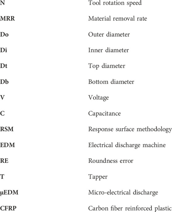
Keywords: micro drilling, capacitance, tool rotation speed, roundness error, MRR, μEDM, CFRP, RSM
Citation: Kaushik N, Jha SK and Anand RS (2023) Experimental investigation of micro EDM drilling in the CFRP using response surface methodology. Front. Mater. 10:1147882. doi: 10.3389/fmats.2023.1147882
Received: 19 January 2023; Accepted: 16 June 2023;
Published: 29 June 2023.
Edited by:
Longbiao Li, Nanjing University of Aeronautics and Astronautics, ChinaReviewed by:
Kaushik Kumar, Birla Institute of Technology, IndiaCopyright © 2023 Kaushik, Jha and Anand. This is an open-access article distributed under the terms of the Creative Commons Attribution License (CC BY). The use, distribution or reproduction in other forums is permitted, provided the original author(s) and the copyright owner(s) are credited and that the original publication in this journal is cited, in accordance with accepted academic practice. No use, distribution or reproduction is permitted which does not comply with these terms.
*Correspondence: Ravi Shankar Anand, cmF2aXNoYW5rYXJhbmFuZEBiaXRtZXNyYS5hYy5pbg==
Disclaimer: All claims expressed in this article are solely those of the authors and do not necessarily represent those of their affiliated organizations, or those of the publisher, the editors and the reviewers. Any product that may be evaluated in this article or claim that may be made by its manufacturer is not guaranteed or endorsed by the publisher.
Research integrity at Frontiers
Learn more about the work of our research integrity team to safeguard the quality of each article we publish.