 Raj Kumar Gnanasekaran1
 Balasubramanian Shanmugam2
 Vijayanandh Raja1
 Hussein A. Z. Al-Bonsrulah3,4
 Parvathy Rajendran5,6*
 Jeeva Radhakrishnan7
 Sayed M. Eldin8*Venkatesh Narayanan9
- 1Department of Aeronautical Engineering, Kumaraguru College of Technology, Coimbatore, Tamil Nadu, India
- 2Department of Mechanical Engineering, Kumaraguru College of Technology, Coimbatore, Tamil Nadu, India
- 3Al-Amarah University College, Maysan, Iraq
- 4AlSafwa University College, Karbala, Iraq
- 5School of Aerospace Engineering, Universiti Sains Malaysia, Engineering Campus, Nibong Tebal, Malaysia
- 6Faculty of Engineering and Computing, First City University College, Petaling Jaya, Selangor, Malaysia
- 7Department of Mechanical Engineering, S. A. Engineering College, Chennai, Tamil Nadu, India
- 8Center of Research, Faculty of Engineering, Future University in Egypt, New Cairo, Egypt
- 9Aerospace Engineering, SNS College of Technology, Coimbatore, Tamil Nadu, India
Most failures develop as a result of a lack of resistivity information at the internal structure level during typical loading situations such as shock load and impact load. Impact loads have a significant impact on a component’s structural performance. A careful, organized examination of impact load settings and their side effects can reveal how well something can withstand peak loads. First, this study investigated the impact analyses on nine varied lightweight composite materials through a conventional experimental setup and computational tools. So, the best three lightweight materials are shortlisted for further investigation under complicated explicit analysis. Second, the study investigated the behavior of composite materials subjected to rapid loading circumstances in several real-time applications. The applications chosen include bullet crash analysis, unmanned aerial vehicle (UAV) propellers, and car bumpers. The three different principal composites, carbon fiber-reinforced polymer (CFRP), glass fiber-reinforced polymer (GFRP), and Kevlar fiber-reinforced polymer (KFRP), are selected and applied in crash analysis using ANSYS Workbench’s explicit technique-based finite element analysis (FEA). The comparison assessments are conducted using stumpy structural characteristics such as impact stress and equivalent strain. Two distinct grid convergence tests were performed to check whether the computational processes and discretization were correct. The standard methodologies were used on all three selected real-time applications, resulting in error percentages that were within acceptable bounds, ensuring the generation of dependable structural outputs. The ideal composite material is a Kevlar fiber-based composite with minimal defect affectability for all types of crash applications. Furthermore, multidisciplinary optimizations are performed, and the KFRP is verified to give good crash load resistance with reduced dense contribution.
1 Introduction
Composites are being implemented everywhere because of their high stiffness-to-weight ratio. Nowadays, the researcher’s important assignment is to increase the use of composites in complicated problems by reducing their low resistivity factor on various testing applications. In particular, impact load resistivity plays a vital role in the selection of the best composite material. In spite of advanced methodology invention, confusions still exist on the suitable material for impact load in the material industry. Hence, this work deals with comparative studies on various composite materials such as carbon fiber-reinforced polymer (CFRP)-, glass fiber-reinforced polymer (GFRP)-, and Kevlar fiber-reinforced polymer (KFRP)-based composites under impact loading conditions. The Charpy method is used in this work for the estimation of properties of shortlisted composites with the help of experimental test facilities. The computational structural analyses are conducted using ANSYS Workbench 16.2. The dimensions used for both analyses are 80 mm length, 10 mm thickness, and 10 mm breadth.
Engineering techniques are available for handling complex real-time challenges. The precision with which these issues are solved is determined by the advanced techniques used in these approaches to solve complex problems. Moving reference frames, dynamic meshes, and other advanced approaches are examples of advanced techniques. Explicit analysis may handle issues such as rotor aerodynamics, acoustic analysis, and fluid–structure interaction. In this study, explicit analysis is applied for material optimization in a collision/crash situation. Crash impacts are often anomalous, which implies that the consequences on both impacted items are non-linear fluctuations in their internal structure. Naturally, three crash possibilities exist: collision between two objects (cars), collision between a vehicle (object) and a roadside barrier, and collision owing to sideslip force of other vehicles. Because of its high requirements and frequent occurrence, the collision between the component and barrier case was chosen for investigation in this work.
Because of their unique properties, composite materials are preferred for usage in critical applications such as ultra-thermal circumstances, abrupt mechanical loading conditions, greater frictional conditions, and hydrodynamic loading conditions. The matrix’s adhesive component can serve as a platform for the addition of numerous relevant mixes. Property enhancement is achieved in composites using suitable combinations such as carbon nanotubes, deflons, and silicon carbide in order to efficiently handle complex situations. Aside from this matrix flexibility, the composite’s load transformation character is significantly good, which greatly helps withstand the rapid impact load. The type and orientation of the fiber and the adhesive quality of the matrix have the greatest impact on the loading conditions. Because of the participation of various components, the load is gradually altered throughout the composite structure. Furthermore, low weight is a growing aspect in composites, which greatly boosts the composite’s implementation in the previously stated key applications. Naturally, impact loads are difficult to cope with; thus, composite components must be capable of dealing with structural variables such as typical loading conditions and delamination. Because of this, sophisticated, structurally relevant fibers such as carbon, glass, and Kevlar are used in this comparison. Furthermore, two matrices, epoxy resin and polyester resin, were structurally analyzed, with epoxy resin being better in tackling ultra-structural difficulties with a risk of delamination failure. As a result, epoxy resin is used as a matrix throughout this study.
The internal bond between the fiber and matrix must be linked perfectly in order to withstand external and internal loading conditions. In general, the failure will occur because of this bonding breakage by continuous loading conditions, and thus, the same environment may possible to enforce into an unpredictable cum non-linear region, which is called the ultimate withstanding region of a specific material. Each and every loading is different in the nature of implementation and its effect. Some of the external loads such as tension and compression work in a linear manner. The bond breaking of the material’s element might have occurred in the non-linear manner at few of the loading conditions, which are shear load, fatigue load, impact load, etc. This work deals the behavior of composite materials under impact loading conditions using different engineering approaches such as the Charpy impact test, scanning electron microscope (SEM) methodology, and computational study.
1.1 Relevant research
Literature surveys were crucial to the completion of complex tasks including impact assessments, fatigue life estimates, and shear stress estimations. This article investigated bumper collision investigations using ANSYS Workbench. The bumper absorbed impact energy from collisions to protect passengers. This work optimizes bumper materials by impact analysis through ANSYS. The analysis technique involved conceptual bumper design and bumper preparation for numerical analysis. Structural parametric results, including the equivalent stress induced and total deformation, are major factors involved in this study. CATIA modeled the reference component, and ANSYS Workbench 16.2 analyzed the bumper’s impact with steel and glass fiber-based composite materials and constant boundary conditions (speed = 13.3 m sec−1). The bumper material was finalized. The following elements have a significant impact on the accuracy of production projections under extreme stress: crash analysis time step and end time; suitable moving object velocity; mechanical characteristics of composite materials; support circumstances; impact strength formula; and theoretical predictions of crash stress are all part of this analysis (Raj Kumar et al., 2019).
A Formula 1 racing car front end was studied by Belingardi and Obradovic (2011) who found that the CFRP performed very well in the event of an accident. The primary goal of this study was to examine the crashworthiness response of an impact attenuator using experimental and numerical analyses. The research materials, design standards, and mechanical characteristics of the materials are noteworthy features of this effort. Numerical experiments were performed by Smojver and Ivančević (2017) to conduct a soft-body impact study of bird strikes. They used high-velocity impacts to harm the target’s internal organs by inflicting foreign object damage. Coupled Eulerian–Lagrangian formulation was used, and the numerical findings were confirmed using experimental data. Matzenmiller and Karl (1991) designed a numerical test for cylindrical and conical structures under longitudinal impact loads in order to ensure trustworthy findings for complicated constructions built of heterogeneous composite material. Standard values for vehicle crash testing were used to create their boundary conditions. Shells were discretized with even spacing, but their length grew row by row in the axial direction. The maximum internal force was determined by the shell’s form. There were three distinct forms of failure that were identified based on wall thickness for a glass fiber epoxy laminate for progressive damage when the composite was subjected to axial impact loading: fabric-reinforced materials are often more effective in absorbing energy than unidirectional materials, according to Boria and Belingardi (2012). To create GFRP material with specified energy absorbers, the author was given a technique. The relevance of orthogonal features, forms of reinforcement, and matrix-based inputs are only a few of the findings that stand out in this study. In order to accurately anticipate the energy absorption capacity of the CFRP, Bussadori et al. (2014) designed and analyzed two alternative types of finite element models. They analyzed aspects such as the model-to-hit object coefficient of friction and the inter-laminar material qualities. Zhou et al. (2020) defined the continuum damage mechanics of intra-laminar damage as the impact damage to composite laminates. According to ASTM standards, the author used an ASTM-standard square plate with dimensions of 500 mm × 500 mm and an average thickness of 3.6 mm. There are three primary findings from this study: the computational approach, specimen information, and boundary conditions.
Kesavan et al. (2021) investigated the detailed work on the KFRP. Kevlar is a heat-resistant synthetic fiber. Kevlar fibers are used in bullet-proof vests, military helmets, and reinforced tires, making them the main composite in all emerging technical goods. This research study proposed using Kevlar-based composite materials in more sophisticated applications due to their enhanced properties. Using a new simulation tool, this work analyzes Kevlar fiber. This study analyzes Kevlar fiber under tensile and bending loading using ANSYS. Analysis is performed at several viewpoints. Grid convergence tests verify computer operations. Traditional analytical formula-based validation reduces error percentages to acceptable levels. Finally, equivalent stress, strain energy, and deformation are used to optimize the fiber angle orientation. Models 20, 27, and 31 performed well under peak loading situations (Kesavan et al., 2021).
Ramesh et al. (2022) investigated the impact under fluid–structure interaction (FSI) loading conditions. Real boundary conditions, including accurate load conditions, perfect supports, and pure mechanical properties, are crucial to the accuracy of any numerical simulation’s output control. Preliminary actions, such as assessing real-time load circumstances and determining properties, are obligatory in the case of complex numerical simulations and must be completed in order to arrive at a satisfactory solution. Furthermore, sophisticated numerical simulations can tackle complex problems. This article presents an FSI analysis of the effects of impact on several composites made from carbon, glass, and Kevlar fibers. The ANSYS composite pre-processor (ACP) tool is in charge of creating the various composites, whereas the ANSYS DesignModeler is used to build the conceptual design. Finally, after conducting impact comparison tests, the most suitable material is selected for impact application (Ramesh et al., 2022).
Vijayanandh et al. (2022) studied the characteristics of various material mechanical behaviors under complicated impact loading conditions. Fluid–structural phenomena cause most modern issues. Aerodynamic and other loads can cause failure in real-world applications such as railway frontal affection, car issues, aviation impact loads, and wind turbines. As a result, FSI research on a wide range of lightweight materials is vital because it promises to produce lightweight materials that can consistently sustain aerodynamic loads in the aforementioned industrial situations. This research study uses numerical analysis to solve continuum mechanics difficulties. Complex geometries, fluid mechanics, and fluid–structure interactions make computational solutions complex. The FSI description has a good possibility of eliminating computational errors. A simulation using a one-way coupled methodology may reduce the FSI workload. In this study, we use FSI analysis to examine the impact of aerodynamic loads on many composites. The one-way coupling-based approach has been studied in subsonic computer simulations. ANSYS Fluent estimates the aerodynamic pressure force applied to the standard test specimen. The ANSYS ACP tool creates composites, while the DesignModeler creates conceptual designs. After a series of comparative impact studies, the optimal material for impact use is identified (Vijayanandh et al., 2022).
Under very complex impact loading conditions, Bhagavathiyappan et al. (2020) investigated the mechanical behavior characteristics of a wide range of materials. The application of sophisticated numerical simulation methods frequently enables engineers to overcome difficult challenges and find successful solutions. These difficulties include, among others, those that result from working in a hostile environment or from the complicated nature of construction. Studies of impact behavior on a variety of composites by means of system coupling are the primary emphasis of this body of work, which is also concerned with a complicated issue of a similar kind. ANSYS DesignModeler 16.2 is used to model the conceptual design of composite test specimens, with ASTM standard dimensions serving as the basis for the modeling. After the fiber and matrix assignments have been completed in ANSYS ACP-Pre 16.2, it is possible to generate a laminate that is composed entirely of composite material. Ten distinct composite models are constructed using ANSYS structural 16.2, and their underlying structures are investigated while the models are subjected to impact loads. In the end, they examined each other’s findings and selected a strain-energy-based optimization as the best option (Bhagavathiyappan et al., 2020).
Composites are damaged experimentally and numerically by low-velocity impact. A cylinder-shaped head gives a model unidirectional CFRP laminate beam a nearly homogeneous two-dimensional loading condition in drop-weight impact testing. An ultra-high-speed camera can show damage initiation and progression, including matrix cracks and delamination, in real-time. Digital image correlation analysis quantifies dynamic strain fields in the laminate, and a digital microscope characterizes failure patterns. They simulated the tests of three-dimensional finite element analysis in ABAQUS/Explicit. A unique subroutine models based intraply matrix damage in the intermediate 90° layers are using CDM composite failure theory with LaRC04 initiation criterion. The 0°/90° interfaces are delaminated with cohesive interface components. This analysis compares experimental damage start time, location, and failure type interactions. Real-time delamination and diagonal matrix cracks are found. In addition to massive diagonal matrix breaks, simulations show multi-diagonal micro-matrix cracks near the upper interface. Finally, the experimental strain field, failure mechanisms, and failure sequence match the models. Here, extensive experimental data for a hypothetical composite layup are presented to assess composite and interface damage modeling methodologies (Tanay Topac et al., 2017).
Each aircraft component’s design should minimize weight, optimize durability, and increase life while minimizing life cycle costs. Jet-powered unmanned combat aerial vehicles (UCAVs) are currently flying, presenting many obstacles. High-speed, high-payload UCAVs need crashworthy landing gears. Jet-powered UCAVs are more likely to crash due to their higher touchdown velocity. Unmanned combat aircraft vehicles were selected for this study. Literature review and analysis were used to extract the major landing gear specifications and dimensions of several reference unmanned combat aircraft vehicles. Modeling the primary landing gear followed. Loads and loading conditions were determined concurrently. Finite element analysis for different materials using ANSYS yielded comparable von Mises and maximum primary stresses. These results were used to compute the safety factor. In this crashworthiness investigation, explicit dynamics in LS-DYNA was used to analyze impact. Impact stress formulations and deformations were non-linear, realistic, and correct. Verification followed (Swati et al., 2022).
An in-house dynamic explicit method was designed to simulate sheet metal-forming processes using a new solid-shell element and a co-rotational coordinate system to simplify non-linearity and integrate the element with anisotropic constitutive laws. To avoid volumetric and thickness locking, the solid-shell element’s enhancing parameter was reduced to an explicit form. To eliminate rank deficiency, the B-bar approach and reconstruction of transverse shear components were used in a modified physical stabilization. An adaptive mesh subdivision system was developed for numerical applications to improve solid-shell element computing efficiency. Element geometry and contact condition were subdivision criteria. Three anisotropic yield functions were used in material models to accurately represent sheet metal anisotropy. Numerous numerical examples were run to verify the proposed element’s accuracy and adaptive mesh subdivision’s efficiency (Li et al., 2022).
ANSYS/LS-DYNA was used to assess cylinder piston impacts for safety and stability. Based on explicit dynamics theory, a cylinder piston finite element impact model was created. Numerical simulation calculated the piston surface stress distribution, impact force variation, and maximum impact force–piston starting impact velocity relationship. Due to the collar between the piston and the force transducer, the impact force on the force transducer is 81% of that on the cylinder piston, and the stress near the piston’s surface center is higher than elsewhere. The results also reveal that impact force, not impact time, is proportional to initial impact velocity (Yan and Wang, 2012).
The author claims that the best-designed sandwich plates can survive water shocks that are twice as strong as those that would break the monolithic plates of the same mass and material. Metal sandwich panels with a variety of lightweight core topologies have garnered significant attention for their potential to dampen shocks, both in general and in the context of submarine propagating shocks in particular. Scientific investigation on the fluid–structure interaction between shock fronts traveling through water and stainless steel sandwich panels has been conducted using a water shock tube. The core of these sandwich panels can be made of honeycomb or a pyramidal lattice, and both are equally dense. The panel’s response to impulsive loading has been predicted using finite element modeling, which has been used to study the underlying deformation mechanisms of the core parts. In order to compare the mechanical performance of different core topologies, Mori et al. developed an analytical model based on the different times required for core crushing and water cavitation. The author proposes a homogenized constitutive model that accounts for rate dependence due to both material rate dependence and micro inertial effects. Filling the core’s voids with low-density polymeric foams to increase its structural strength has been argued to have neither a major advantage nor a major disadvantage (Mori et al., 2007).
An uncontained engine failure can severely harm aircraft systems; thus, designers must address this possibility. To avert catastrophic consequences, numerical modeling of an uncontained engine failure must be enhanced and the negative impacts mitigated. This study simulates ballistic impact testing on a typical aircraft material at high strain rates. Ballistic impact observations at different material thicknesses feed explicit finite element (FE) simulations of ballistic limits. Simulations use a non-linear explicit dynamics FE technique (LS-DYNA). We use an adjustable thermo-viscoplastic Johnson–Cook material model, a non-linear equation of state, and an accumulated damage evaluation algorithm for numerical simulations. Material characterization efforts, material model parameters, mesh sensitivities, and stress triaxiality are discussed in relation to numerical model prediction performance. Mesh refinement will not improve ballistic limit simulations until these interrelated elements are analyzed and calibrated. Existing models that fit a single function for damage evaluation as a function of stress triaxiality cannot consistently predict failure, especially in the presence of significant stress changes (Buyuk et al., 2009).
This study evaluates four ECU drop test simulation approaches. This study considers explicit and implicit simulation methodologies. Full transient, steady-state static, and mode super position implicit simulation approaches are compared to explicit methods. Unlike implicit approaches, explicit simulation methods are conditionally stable, making them computationally more expensive and time-consuming. An implicit approach struggles with convergence and dynamic response. This study simplifies the electrical control unit with a bare PCB and frame for drop simulation. PCB in-plane stresses and displacements are measured for a 1-m drop on a rigid floor and compared to determine which method works best (Balakrishnan et al., 2017). With the help of these relevant literature reports, the problem’s descriptions and its solution techniques are found out. The comprehensive explanations are given in Section 1.2 and Section 1.3. Second, the detailed studies of impact load-withstanding behaviors of various lightweight materials are studied and compared with computational outcomes. The validated computational conventional procedures are extended for other lightweight materials, and so, the suitable material is found. Third, the detailed investigations of withstanding behaviors of various lightweight materials under crash load are studied and compared with computational outcomes. The validated advanced computational procedures are extended for other lightweight materials, and so, the suitable material is found. Fourth, the final conclusion is mentioned.
1.2 Problem description of conventional analysis
The fundamental problem in structural engineering is to provide a suitable material for abnormal loading conditions in which the suitable material has to withstand ultimate boundary conditions without affecting its lifetime. Therefore, the external load imposing on this material needs to counteract two actions, which are resisting ability at ultimate loading conditions and provision of a high lifetime by reacts normal peak forcing environments. Composite material is the best option to overcome these critical behaviors, so in this work, familiar composite materials such as GFRP and CFRP are selected for comparative structural analyses. In general, the structural analyses fully depend on the type of external load applied and its nature. Also, the structural outputs induced in the test specimen fundamentally rely on the nature of the support and its geometrical and mechanical properties. The kind of non-linear loading is the primary focus of this work, in which impact load is shortlisted as an external loading category. Structurally, the impact loads are able to create to a double effect on the test specimen because of its sudden acting nature. Due to this atypical nature, the sudden impact loads are implemented in the composite test specimen as a peripheral force. Because of the critical acting nature, the impact-loaded test specimens are reacted differently at various perspectives based on their fiber-holding property and their stiffness-to-weight ratio. In this work, two different engineering methodologies are used, in which experimental testing is used to find the rupture load, and numerical simulations are used to find the stresses and deformations at rupture-loading conditions. Also, the working character of numerical simulations and the impact analyses are extended for all the advanced composite materials, and then, the comparative analysis is executed (Mori et al., 2007; Buyuk et al., 2009; Yan and Wang, 2012; Balakrishnan et al., 2017; Caputo et al., 2017; Kumar et al., 2017; Mylsamy et al., 2020; Palaniappan et al., 2020; Naveen Kumar et al., 2021; Aruchamy et al., 2022; Nagappan et al., 2022; Raja et al., 2022; Sharaf et al., 2022; Zhang et al., 2022). The detailed step-by-step procedures involved in this comparative analysis are given in the flowchart in Figure 1.
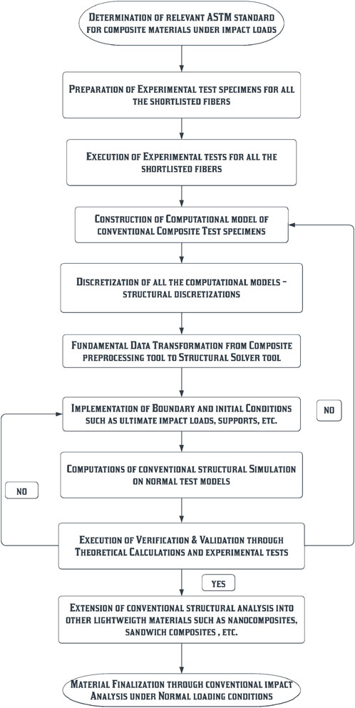
FIGURE 1. Working flowchart of conventional impact analysis.
1.3 Problem description and procedures involved in advanced crash analysis
Explicit dynamics-based time integration is used in time-critical dynamic simulations. It is necessary to explicitly account for dynamics in cases such as free falls, high-velocity impacts, and applied loads. Explicit dynamics is preferred for modeling highly transient physical processes because “non-linear dynamics” can be incorporated into the simulation. While the central difference approach is used for time integration in transient structural simulations, it is used in ANSYS’s explicit dynamic analysis. Explicit dynamic analysis is useful for problems that involve fast-moving, highly non-linear dynamics. For the explicit method to work, the time step must be less than a specified value, which can be either the minimum element size of the generated mesh or the order of the element. However, the time step value is no longer a question of precision when using the implicit method. To deal with dynamic finite element analysis (FEA) issues with low-order non-linearity and large time increments, implicit dynamics can be used. The detailed step-by-step procedures involved in this comparative analysis are given in the flowchart in Figure 2.
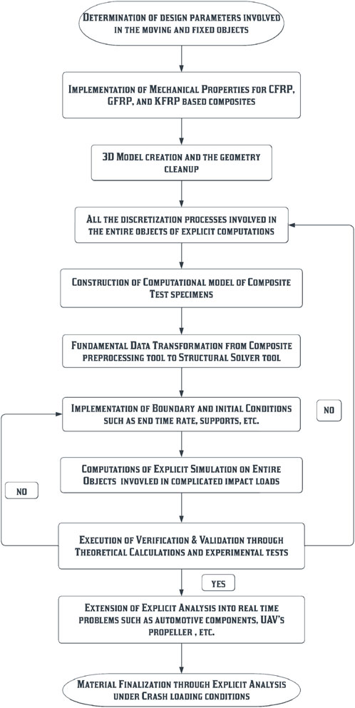
FIGURE 2. Working flowchart of advanced explicit analysis.
2 Methodologies used and its results—conventional impact analysis
ASTM D256 has played a major role in the development of test specimens under this conventional impact test. The experimental setup involved in this conventional impact test is shown in Figure 3. The test specimen details are as follows: 80 mm in length, 10 mm in breadth, and 10 mm in thickness. The cross-sectional area is calculated as 170.25 mm2 (11.35 × 15). The number of layers used for this construction is 30 (woven type) (Bhagavathiyappan et al., 2020).
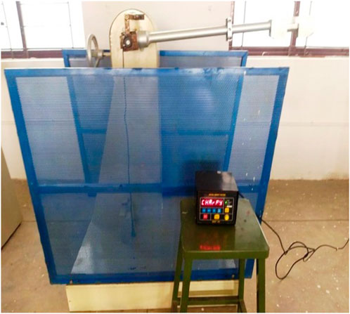
FIGURE 3. Experimental setup of the impact test.
2.1 Experimental test and results
The typical test specimens of the GFRP and CFRP are shown in Figures 4A, B, respectively. The dimensions of these test specimens are constructed as per the guidance of ASTM D256 (Bhagavathiyappan et al., 2020).
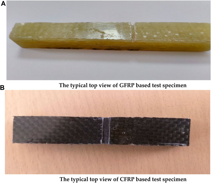
FIGURE 4. (A) Typical top view of the GFRP-based test specimen. (B) Typical top view of the CFRP-based test specimen.
The test specimens are fixed on the correct location where the needful impact collision needs to occur between the test specimen and the steel hammer. As per the generalized test procedures, the impact tests are carried out on both GFRP and CFRP test specimens. After the impact tests, the yielded test specimens are carefully monitored, and the experimental outcomes are noted. The typical representations of ruptured test specimens are shown in Figures 5A, B.
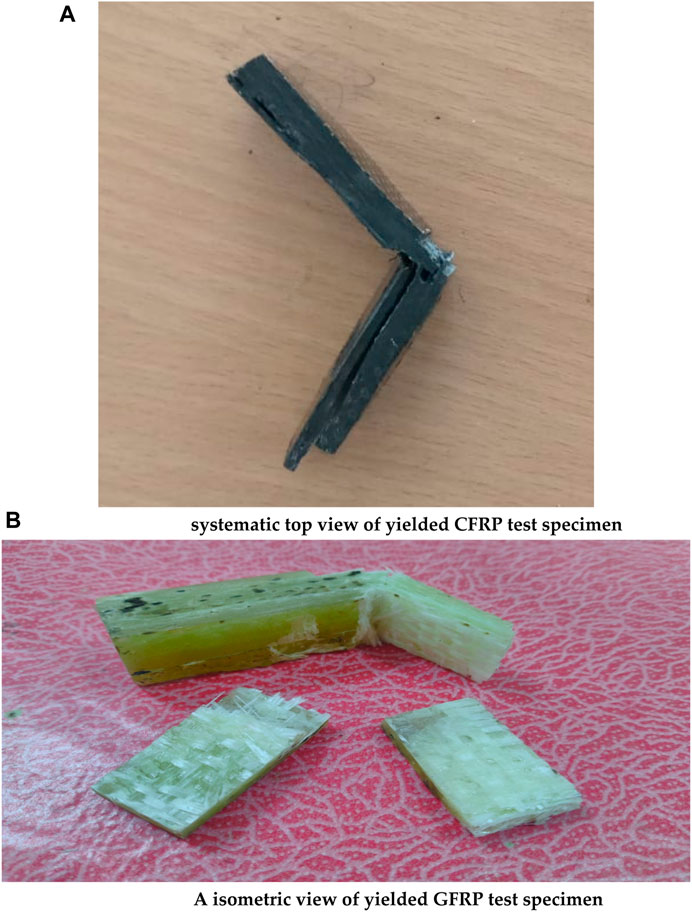
FIGURE 5. (A) Systematic top view of the yielded CFRP test specimen. (B) Isometric view of the yielded GFRP test specimen.
After the brake, the internal bond connections between the molecules of both the CFRP and GFRP are clearly viewed; they further enhance the development polymer composite materials in an effective manner. The internal collapsed view of both CFRP and GFRP test specimens is shown in Figures 6A, B, respectively. The impact outcomes are calculated using conventional procedures (Javadova et al., 2022; Murvatov et al., 2022).
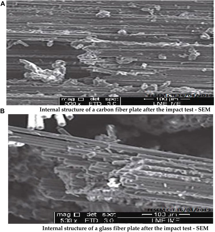
FIGURE 6. (A) Internal structure of a carbon fiber plate after the impact test—SEM. (B) Internal structure of a glass fiber plate after the impact test—SEM.
2.2 Computational structural analysis of polymer matrix composites (PMCs)
In its most basic form, mathematical modeling is composed of governing equations that are stated within a field and boundary conditions that are provided at the limits of the region being modeled. Because composites are the primary platforms for this activity, it is necessary to incorporate two more crucial equations in order to obtain outputs that are both required and acceptable. The equations that are important here are the three-dimensional form of Hooke’s law and the linkages between strain and displacement. In conclusion, nine major equations are put to use for the most part in this impact stress computation that is based on a FEA. Because deformation and stresses will be used as selection factors for this study, two fundamental governing equations are required. The equation for the forces balance, which is derived from Newton’s second law, and the equations for the normal stresses are the two most important equations for managing the system. Equations 3, 4 provide force–balance equations in all three different directions (Naveen Kumar et al., 2021; Raja et al., 2022).
Equations 4–6 provide the normal stress equations in all three directions for polymer matrix composites, whereas Eqs 7–9 provide the normal stress equations in all three directions for key alloys (Naveen Kumar et al., 2021; Raja et al., 2022).
The computational model involved in this comprehensive computational investigation is shown in Figure 7A. Since the conventional test specimen has a less complicated design profile, the structural mesh is more suitable for this discretization. Uniform discretization is imposed upon this impact test specimen, and so, the quality is achieved with a maximum of 0.9995 (Naveen Kumar et al., 2021; Raja et al., 2022).
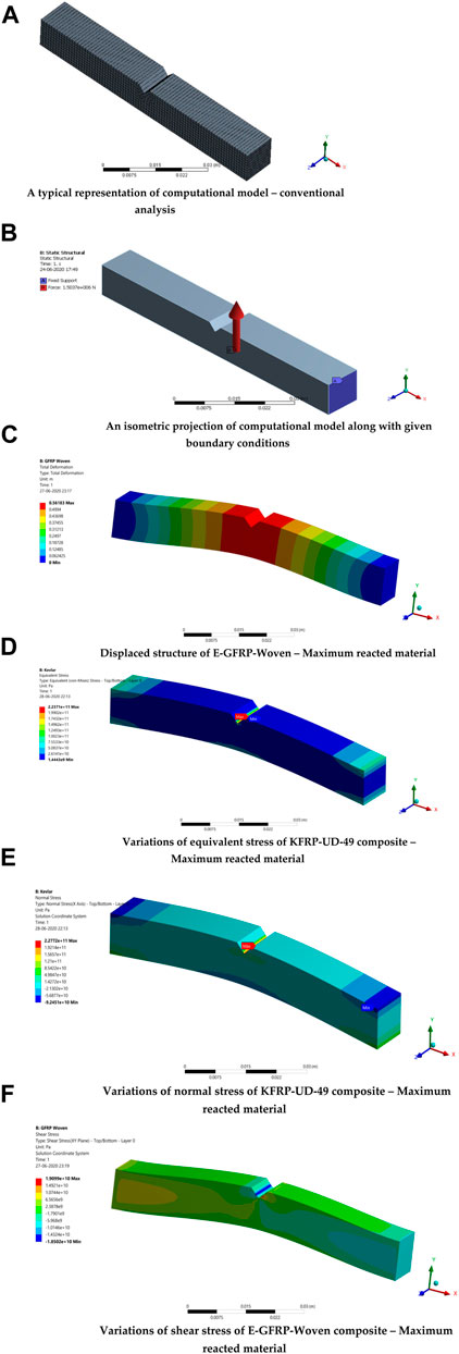
FIGURE 7. (A) Typical representation of the computational model—conventional analysis. (B) Isometric projection of the computational model along with the given boundary conditions. (C) Displaced structure of the E-GFRP-woven composite—maximum reacted material. (D) Variations of equivalent stress of the KFRP-UD-49 composite—maximum reacted material. (E) Variations of normal stress of the KFRP-UD-49 composite—maximum reacted material. (F) Variations of shear stress of the E-GFRP-woven composite—maximum reacted material.
As per the conventional impact tests, the boundary conditions and supports imposed in this comparative computational investigation are obtained. Figure 7B shows the detailed boundary conditions given in this investigation. The imposed boundary conditions are fixed support at the extreme edges and impact load at the middle edge. The force of 1,503,671.07 N has been obtained as an external load from the impact test and the same value is provided as the impact force for this investigation. The relevant displacement functions are assumed on every element of this discretized computational test model structure. Through the ANSYS structural solver, this computational model is computed, and so, the important structural outcomes are shown in Figures 7C–F. The maximum reacted material cases of structural outcomes such as deformation, equivalent elastic stress, normal stress, and shear stress are shown in Figures 7C–F, respectively.
The comprehensive structural outcomes of deformation, equivalent elastic stress, normal stress, shear stress, strain energy, and equivalent elastic strain are shown in Figures 8A–F, respectively. In Figures 8A–F, the following observations are noted: the E-GFRP-woven and KFRP-UD-49-based PMCs failed to react reasonably under the impact load. Hence, these said materials are unfit to provide high lifetime for impact load-based real-time applications. CFRP-UD-Wet and S-GFRP-UD are the materials picked as the best performers and also suggested for use in complicated applications. Thus, these two aforesaid materials are underwent other complicated impact investigations, which are explained in the forthcoming sections.
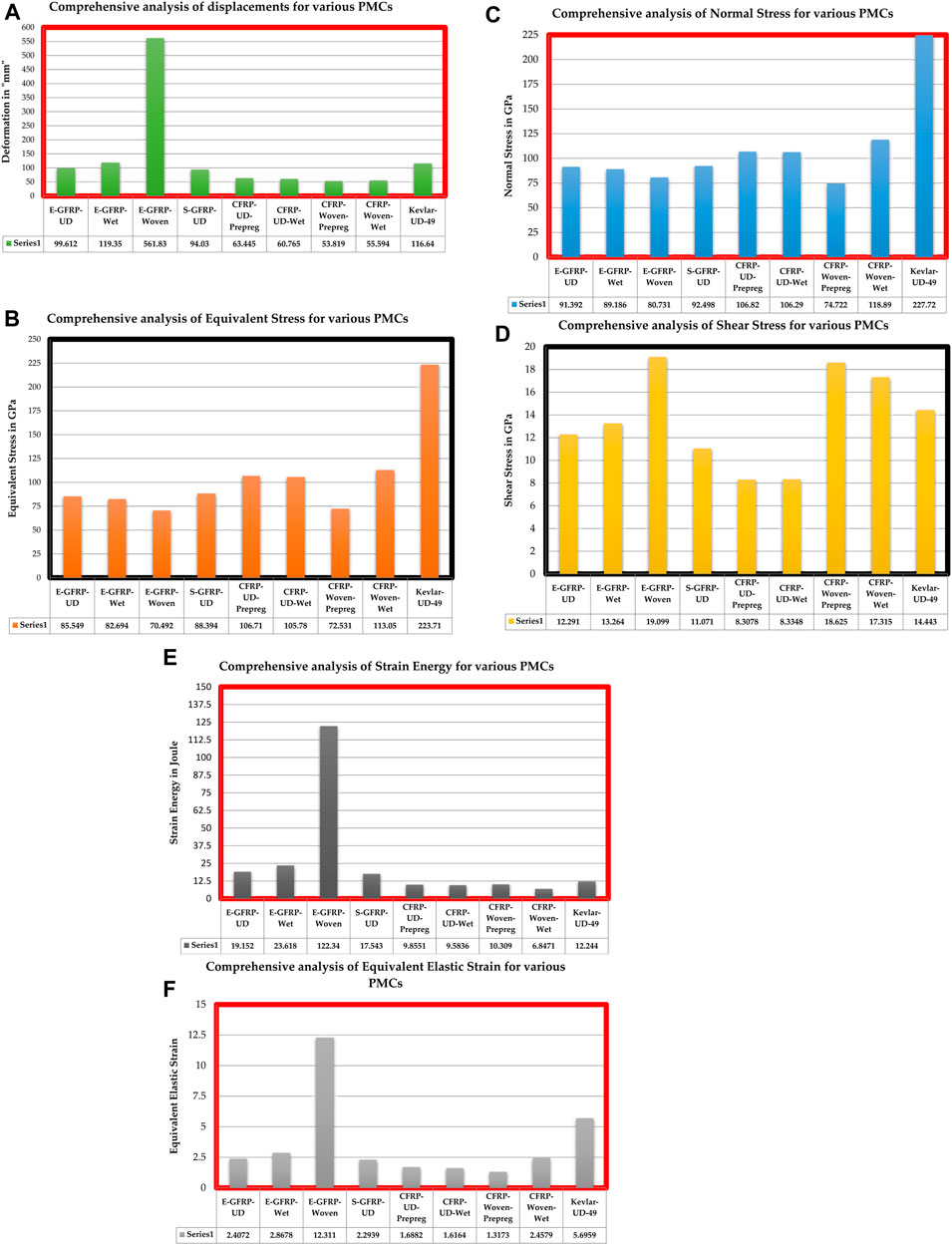
FIGURE 8. (A) Comprehensive analysis of displacements for various PMCs. (B) Comprehensive analysis of equivalent stress for various PMCs. (C) Comprehensive analysis of normal stress for various PMCs. (D) Comprehensive analysis of shear stress for various PMCs. (E) Comprehensive analysis of strain energy for various PMCs. (F) Comprehensive analysis of equivalent elastic strain for various PMCs.
3 Advanced methodology implemented and its results—explicit crash investigation
Explicit dynamics is needed due to the complexity and non-linearity of the underlying problems in scenarios such as static equilibrium; sluggish, linear, and weak non-linear processes; considerable time steps; and drop tests, impact and penetration, breaking, shock waves, and massive deformations. The comparative advanced crash analyses of this work fully relied on ANSYS-based explicit analysis. The validation is also executed using a standard theoretical calculation in order to validate the numerical explicit outputs. In this work, two types of explicit-dependent numerical investigations are executed, which are ASTM-based standard crash analysis and explicit analysis on the UAV’s propeller (Matzenmiller and Karl, 1991; Belingardi and Obradovic, 2011; Boria and Belingardi, 2012; Bussadori et al., 2014; Smojver and Ivančević, 2017; Raj Kumar et al., 2019).
3.1 Problem formulation of FEA in explicit analysis
Computationally, problem formulation is the process of explanation about the problem description and its solution procedures in an in-depth manner. In general, the FEA comprises a computational model of the test specimen, discretization process involved in the test specimen, description about the nature of the problem, details of boundary conditions used, solver control of the numerical simulation, and governing equations involved in this analysis. All the aforesaid descriptions are explained clearly in a detailed manner in the following sections (Mori et al., 2007).
3.1.1 Computational model
A computational model is the fundamental platform of this comparative explicit analysis. In general, the computational model of explicit analysis comprises a moving object and fixed object. In the first cum validation case, the circular solid bullet is considered a moving object, which is given at a velocity of 100 m/s. The rectangular section is considered a roadside barrier or obstacle object, which is modeled as per the ASTM crash test standard (Matzenmiller and Karl, 1991; Belingardi and Obradovic, 2011; Boria and Belingardi, 2012; Bussadori et al., 2014; Smojver and Ivančević, 2017; Raj Kumar et al., 2019). The distance between the roadside barrier and moving object is given as 1,000 mm. Figure 9A shows the conceptual design of the entire setup of the crash investigation, in which a road safety barrier is fixed 1,000 mm away from the moving object. Also, the dimension details are according to ASTM standards, in which the length, breadth, and thickness of the road safety barrier are 140 mm, 12 mm, and 20 mm, respectively. Apart from these safety barrier dimensions, the bullet diameter is fixed at 10 mm because of its coincidence with the breadth of the safety barrier (Balakrishnan et al., 2017).
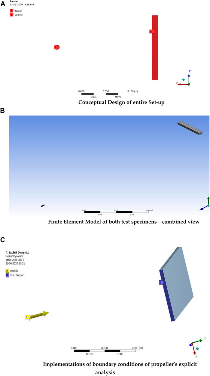
FIGURE 9. (A) Conceptual design of the entire setup. (B) Finite element model of both test specimens—combined view. (C) Implementations of boundary conditions of propeller's explicit analysis.
3.1.2 Discretization
In the explicit analysis, the discretization process is further kept at a high level because of which we can observe the structural outputs in the collision region. In this case, fine structural grids are used to capture the exact phenomena between load implementation and its output extraction. Computationally, the nature of the structural mesh is more accurate than that of the unstructured mesh with the consumption of a low amount of discretized elements (Raja et al., 2022). The fine structural meshes are implemented in both objects, as shown in Figure 9B.
3.1.3 Boundary conditions
In most cases, fixed supports are supplied on both sides of the barrier. This plays a significant part in the induction of the resistive force inside the structure. For the purpose of optimizing the use of the material, moving objects are given composites made of a variety of materials, including GFRP, CFRP, and KFRP. The E-Glass-Fabric-M10E/3783-based fiber is mostly contributed as reinforcement in the GFRP, the Kevlar-49-UD-based fiber is predominantly contributed as reinforcement in the KFRP, and the carbon-woven (230 GPa) wet-based fiber is predominantly contributed as reinforcement in the CFRP. Epoxy resin is typically used as an adhesive for all composites. For each composite, a separate comparative simulation was developed, and the results of those simulations led to the selection of epoxy resin as the material with the highest level of performance (Caputo et al., 2017; Kumar et al., 2017; Mylsamy et al., 2020; Palaniappan et al., 2020; Aruchamy et al., 2022; Nagappan et al., 2022; Sharaf et al., 2022; Zhang et al., 2022). Table 1 (Naveen Kumar et al., 2021) provides a full breakdown of all of the composite materials’ underlying mechanical characteristics.
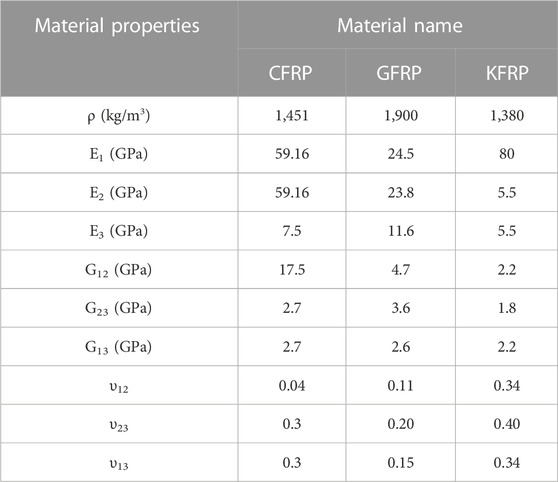
TABLE 1. Mechanical properties of composite materials.
The boundary conditions such as fixed support and input velocity are given to appropriate objects, as shown in Figure 9C.
Figure 9C shows the entire boundary condition details of the UAV’s propeller, which is involved in one of the real-time applications of this work. For the sample and clear representation of this optimization, the UAV’s propeller-based boundary condition is shown in Figure 9C. In a normal case, i.e., a bullet with a barrier, stainless steel is used as the barrier and the aforementioned composite materials are used as the moving bullet. The time taken to reach the barrier from its initial place is 0.01 s. The end time of this complete simulation is given as 0.1 s, which is 10 times greater than the collision incidental duration. To capture the entire structural effect after the collision, the monitoring of both the objects is mandatory, which is why the 10 times greater duration is fixed for this entire explicit simulation (Zhang et al., 2022).
3.1.4 Nature of explicit analysis simulation and its governing equations
Because the primary objective of this study is the optimization of the material and the verification of that optimization, the focus that was originally intended to be placed on the designs of the component parts has, instead, been redirected to the analysis of the structure. An approach with an eagle’s eye view is used to verify many things, including mechanical qualities, the conclusion of the study, and support reactions. The reactance of the internal structure of the material has been formed in a manner that is not uniform due to the dynamic loads and the rapid actions that they cause. A structural failure can be caused in any sort of material by the non-linearity reactance of the material’s internal atomic structure. This can happen in a highly specific way. As a result, a more complex method is required in order to analyze the crash-based non-linear loads’ effects on real-time applications. On this matter, the explicit platform-based FEA solver is selected, and as a result, the simulation has been executed. With the help of previously established initial and boundary conditions, the explicit approach can make accurate predictions regarding the present structural results of the computational model. In the context of time-dependent cum dynamic assessments, the exact same computing approach can be used on all of the different temporal variants. Due to the computational nature of the explicit technique, the crash-based investigations can be completed through the use of the explicit technique in a way that is perfect, swift, and reliable (Sharaf et al., 2022).
The mathematical modeling is made up of governing equations that are defined inside of a field, and boundary conditions that are given outside of the region that is being modeled. Because the composites serve as the primary platforms for this activity, it is necessary to include two substantial additional equations in order to provide outputs that are both required and acceptable. This is because there is a necessity to produce outputs that are both required and acceptable. The strain–displacement connections and the equation for Hooke’s law in three dimensions are the two most significant equations. In conclusion, nine different sub-equations are used nearly primarily in the process of estimating the amount of stress that is caused by the explicit-based FEA. In addition to these primary equations, the dynamic equations are also considered in the phase where the solution is being found (Matzenmiller and Karl, 1991). The solver has a good understanding of the inputs of the current state of the computational model due to the previously described orthogonal qualities and external crash loads. The aforementioned governing equations can be solved in a straightforward manner using FEA methods, which enables accurate prediction of the processes as a whole. It is possible that the anticipated values contain an inaccurate assumption; hence, it is necessary to conduct computational sensitivity testing in order to validate the predicted results. The grid convergence inquiry, impact load-based experimental test, and traditional analytical approach-based estimation are the computational sensitivity tests used in this work for the validations.
3.1.5 Grid independence study—I
The grid convergence research can be understood as an optimization procedure for the mesh. This method is primarily predicated on the mesh’s high quality with regard to its ability to produce accurate results. This optimization investigation is based on a fundamental principle known as the estimation of output variations across all of the mesh cases. This principle selects the smallest quantity of elements possible based on the minute differences that exist between the cases, ensuring that the quality is never considered to be, in any way, compromised. In the process of optimizing this grid, a total of five distinct types of meshes—coarse mesh, medium mesh, fine mesh, fine mesh with individual setup, and fine mesh with inflation—are formed, each of which is determined by the quality of the data it captures. The aforementioned boundary conditions are implemented in each of the five situations, and the KFRP composite is used consistently across all of the cases with no changes or adjustments of any type.
The first case focuses on the coarse mesh setup, while the second case focuses on the construction of pieces with a medium-quality base. In addition to these two situations, this study makes use of three more advanced mesh cases. These cases are fine with a face mesh setup, fine with a curvature cum proximity setup, and fine with an inflation setup. The explicit analysis is difficult, which is why the use of fine meshes is the most common solution to engineering problems. In this regard, fine meshes with boosted facilities are used, and in case III, fine meshes with face mesh facilities are used to implement the explicit analysis in the test specimen. The curvature and proximity capabilities are more capable of capturing warp and area fluctuation regions; hence, those facilities are used in case IV. Lastly, in the design of case V, in which the growth rate is held constant at 1.2, inflation plays a significant role in the process. Table 2 provides an exhaustive list of the information pertaining to the nodes and elements of each and every mesh scenario. Figure 10 shows the comprehensive structural result of the first grid convergence test. The mesh case III solution was selected as the most successful outcome. After case III, the structural findings that were produced are extremely close to one another, which indicated that case III may deliver dependable outcomes despite the utilization of low-mesh components. As a result, the grid setup for the first study will be mesh case III. This choice was made since it requires a minimum amount of processing time and also provides trustworthy results.
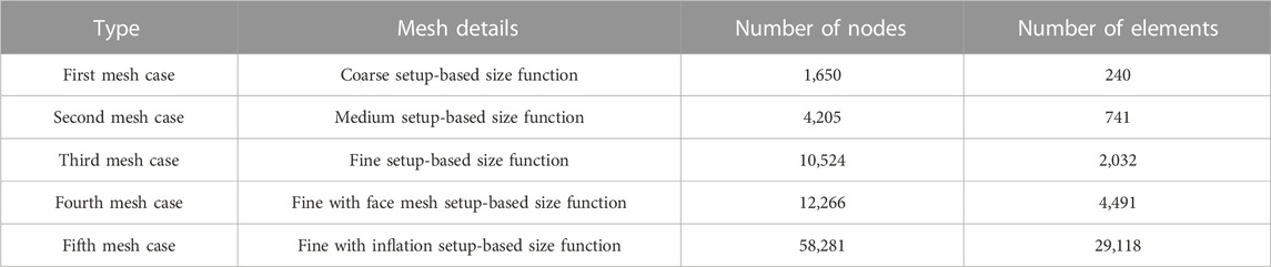
TABLE 2. Comparative data of the mesh details of the standard test specimen.
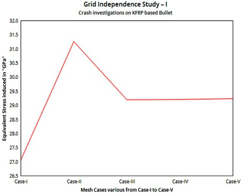
FIGURE 10. Grid convergence test on the base model.
3.1.6 Validation study of explicit analysis
Based on the inserted needful conditions, the sudden environments and its relevant outcomes are computed. The fundamental structural information and major stresses are considered as important selection factors for these comparative investigations.
3.1.7 Computational results
The normal stress, equivalent stress, and equivalent shear strain variations of the CFRP composite test specimen are computed, and the normal stress variation with respect to the applied crash load of the CFRP is shown in Figure 11A. For the same loading conditions, the structural analyses are extended for GFRP and KFRP composites. Figure 11B shows the structural output of CFRP composites, in which equivalent stress variations are primarily represented over the entire bullet and barrier. Finally, the Kevlar composite structural result of normal stresses is shown in Figure 11C.
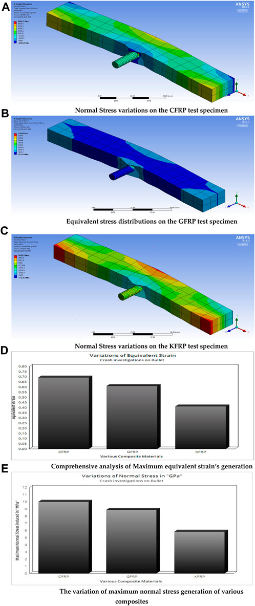
FIGURE 11. (A) Normal stress variations on the CFRP test specimen. (B) Equivalent stress distributions on the GFRP test specimen. (C) Normal stress variations on the KFRP test specimen. (D) Comprehensive analysis of the maximum equivalent strain’s generation. (E) Variation of the maximum normal stress generation of various composites.
The detailed comprehensive representations of all the structural outputs of the composites are given in Figures 11D, E, in which the Kevlar composite is induced with low internal resisting force for the same given loading conditions. Due to this low induction of resistance, the KFRP can withstand more impact loads; therefore, KFRP-based composite objects are more suitable for implementation in crash-based applications.
3.1.8 Theoretical results
Conventional dynamic relationships are implemented in this work in order to calculate the crash force and its stresses. To proceed further, two major conventional principles are considered in this section, which are thermodynamics energy law and Newton’s third law. After the gained knowledge through conventional principles, three major energies are considered important to construct crash-based outcomes. The kinetic energy of the moving object, energy observed by the barrier, and strain energy induced in the moving object are the topmost factors, which can provide the strong relationship between the crash force and its structural results. With these inputs, the following analytical studies are composed:
For Kevlar,
From the literature survey, the crash stress formulae has been found out, which is,
The validation is carried out for the base model, which is the crash investigation on bullets. The comprehensive outcomes of the bullet and its combined barrier are given in Table 3, which contains the error percentage between computational simulation and analytical estimation. A fine-tuned survey was performed on the acceptable limit of error percentage, and the acceptable limit was obtained as 0.1%–10%. Table 3 shows the computed error percentage, which comes under the acceptable limit. Therefore, the implemented explicit simulation is validated. Thus, the proposed explicit-based FEA can provide reliable outcomes for crash investigations.

TABLE 3. Validation in between theoretical calculation and computational simulation of the base model.
3.2 Results and discussion
Because of the strong confirmation, the extension of explicit-based FEA is executed for two more important real-time applications, which are crash investigation on the UAV’s propeller and automotive bumper. Both of these applications contain the toughest working environments, which enhanced the possibility of the failure generation rate on these applications. Thus, the studies about the crash investigation on the aforesaid missions are unavoidable in order to generate the complicated working exposure in all the components involved in these missions. This work strongly assured that, through this extension, the clear exposure about peak loading conditions and their structural affects will be obtained, which enhance the lifetime of the components involved in the aforementioned applications.
3.2.1 Real-time applications—I
The UAV’s propeller (6 × 4.5) is considered as the moving objects, which is given a velocity of 75 m/s. The maximum velocity of the advanced UAV can fly up to the speed level of 75 m/s. For example, the racing drones can have a maximum velocity of specification of 75 m/s. At high speed, the possible occurrences of crash incidents are quite high, so the same speed is considered as the crash velocity for this work. The rectangular section is considered as the ground, which is modeled as per the ASTM crash test standard, i.e., ASTM F2656 (Matzenmiller and Karl, 1991; Belingardi and Obradovic, 2011; Boria and Belingardi, 2012; Bussadori et al., 2014; Smojver and Ivančević, 2017; Raj Kumar et al., 2019). The distance between the ground and the UAV’s propeller is given as 1 m. Figure 12A shows the design of the entire setup of crash investigation, in which the ground is fixed 1,000 mm away from the UAV’s propeller. The other dimensional details such as the length, breadth, and thickness of the ground object are 140 mm, 140 mm, and 20 mm, respectively. Apart from the ground dimensions, the UAV’s propeller diameter is estimated as 6 inches because of its coincidence with the breadth of the ground barrier.
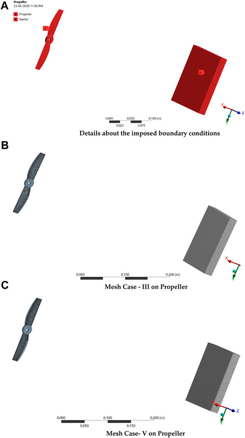
FIGURE 12. (A) Details about the imposed boundary conditions. (B) Mesh case III on the propeller. (C) Mesh case V on the propeller.
3.2.1.1 Grid convergence study—II
The second grid convergence study is conducted on the UAV’s propeller with five cases. The first two mesh cases are followed and constructed in the same manner as from the previous grid convergence test. In addition, three finer-based mesh cases are generated, which are fine with a face mesh setup, fine with a curvature cum proximity setup, and fine with an inflation setup. Figures 12B, C show the two fine meshes, in which fine with face mesh setup (mesh-III case) on the propeller is shown in Figure 12B, and finally, the unstructural fine with inflation (mesh-V case) on the toughest regions is shown in Figure 12C. The whole mesh statistical report is collected and given in Table 4. With these inputs and the aforesaid boundary conditions, the second grid convergence simulation is carried out and mesh case IV is found to be the optimized case, which is implemented in all other simulations. The comprehensive representation is shown in Figure 13.
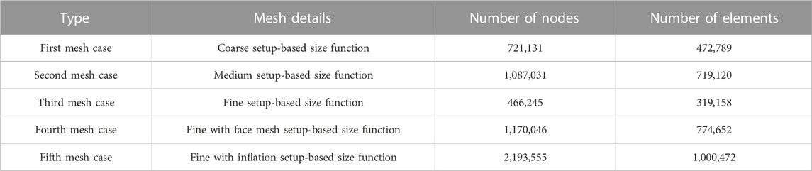
TABLE 4. Comparative data of the mesh details of the propeller.
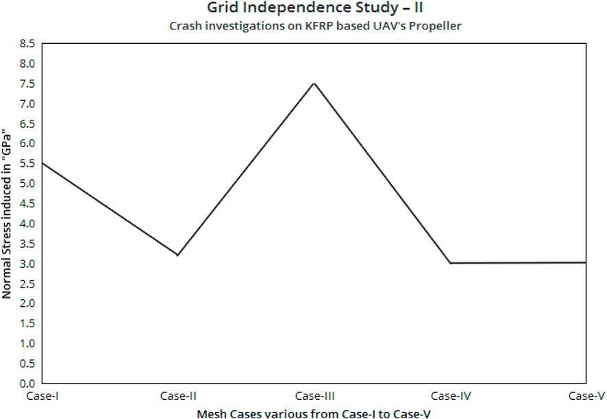
FIGURE 13. Grid convergence test of the UAV’s propeller.
The computational simulations over the UAV’s propeller are computed, and the results are given in Figures 14A, D. Wherein, Figure 14A shows the structural outcomes of the GFRP, Figure 14B shows the structural outcomes of the CFRP, and Figures 14C, D show the comprehensive data of the maximum stress induced inside the UAV’s propeller made up of different composite materials.
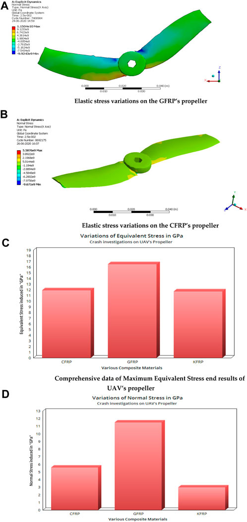
FIGURE 14. (A) Elastic stress variations on the GFRP’s propeller. (B) Elastic stress variations on the CFRP’s propeller. (C) Comprehensive data of the maximum equivalent stress end results of the UAV’s propeller. (D) Comprehensive data of the maximum normal stress end results of the UAV’s propeller.
3.2.1.2 Theoretical estimation—II
In the base model, both computational simulation and analytical approach are verified and validated. Therefore, the same analytical approach has been implemented in these kinds of crash investigations such as the UAV’s propeller and automotive bumper. The major Eqs 12, 13 are imposed in this first real-time application. For the KFRP,
In the case of minimum, the normal stress will be equal to crash stress; thus, the minimum crash stress is equal to 15.56 MPa. The detailed data of the estimated stress induced at the UAV propeller’s tip through both the aforementioned approaches are given in Table 5. As per the observations, the error percentages are obtained, validated, and ensured that the approaches can provide reliable outcomes.
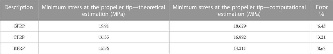
TABLE 5. Validation in between theoretical calculation and computational simulation.
3.2.2 Real-time applications—II
In the automotive domain, the probability of a crash has happened in a high manner. Due to this major accident, the structural failure on an automotive vehicle is created in a non-linear mode in which the bumper plays a major role in the restriction of crash load under accidental environments. Therefore, the bumper is considered an unavoidable component in the crash-based investigations. The second real-time case of this optimization deals with crash investigation on the automotive bumper, wherein the high crash load-withstanding material-based optimization takes place. The dimensions of the automotive bumper were obtained from a literature survey (Raj Kumar et al., 2019), in which 0.975 m is fixed as the effective length, 2.05 m is found as the total length, 0.002 m is obtained as the thickness of the bumper, 0.07 m is used as the effective breadth, and 0.17 m is finally obtained as the total breadth. The steel-based bumper has been used in the automotive sector, wherein steel can resist high crash load more than other materials, but the weight consumption and, thereby, fuel consumption are problematic factors. Thus, this work proposed the comparative composite material-based optimization analysis on the automotive bumper. In this regard, three major composite materials are picked to undergo crash investigation. Finally, the computational results are validated with experimental results. The design of the bumper is shown in Figure 15A. The complicated shape of this bumper is modeled through CATIA.
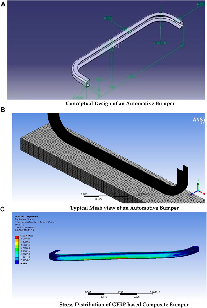
FIGURE 15. (A) Conceptual design of an automotive bumper. (B) Typical mesh view of an automotive bumper. (C) Stress distribution of a GFRP-based composite bumper.
The discretization phase is constructed on the base physical model of this second real-time application, in which fine structural relayed grids are framed. With the help of previously completed grid convergence tests, the grid formation is executed for this case, as shown in Figure 15B. After the grid construction, the statistical and quality reports are captured for the constructed mesh, in which the overall element is counted as 3,578,941, the nodes are noted as 7,489,255, and the mesh quality is observed as 0.99.
The computational procedures for crash investigation were already performed and validated, which predominantly contributed in this case also. In addition to the previous validating procedure, this work imposed experimental test-based verification and validation. Because of this inclusion, a separate impact test is organized at the normal environment through high-speed jet test facility. Utmost care was given to the test specimen preparation and its dimensions, wherein the design data, fiber type, and matrix are captured from the aforementioned literature survey (Raj Kumar et al., 2019). The velocity of the hitting object and its total weight are perfectly noted, which has been given as boundary conditions to the computational simulations. As per the conventional test principle, the impact test is organized on the GFRP-based object, and thus, the structural outcomes are calculated. Through this experimental test, the input velocity and the distance between the objects and supports are captured. The extracted values through the experimental test are the input velocity of the moving object, 50 m/s, and the distance between the objects, 500 mm, and the roadside barrier is made up of steel. Figure 15C shows the stress distribution over the GFRP-based composite bumper. The equivalent stress values are noted perfectly in both the approaches, and the comprehensive reports are given in Table 6.

TABLE 6. Comprehensive stress results between the experimental test and computational simulation.
3.2.2.1 Experimental crash test
To test the reliability of the imposed advanced computation procedures through ANSYS Workbench 16.2, an experimental test-based validation test on the attained computational outcomes is mandatory. Thus, high-speed jet facility-based experimental test results and this work’s imposed computational procedure-based outcomes are compared with each other. The typical high-speed jet facility is shown in Figure 16A.
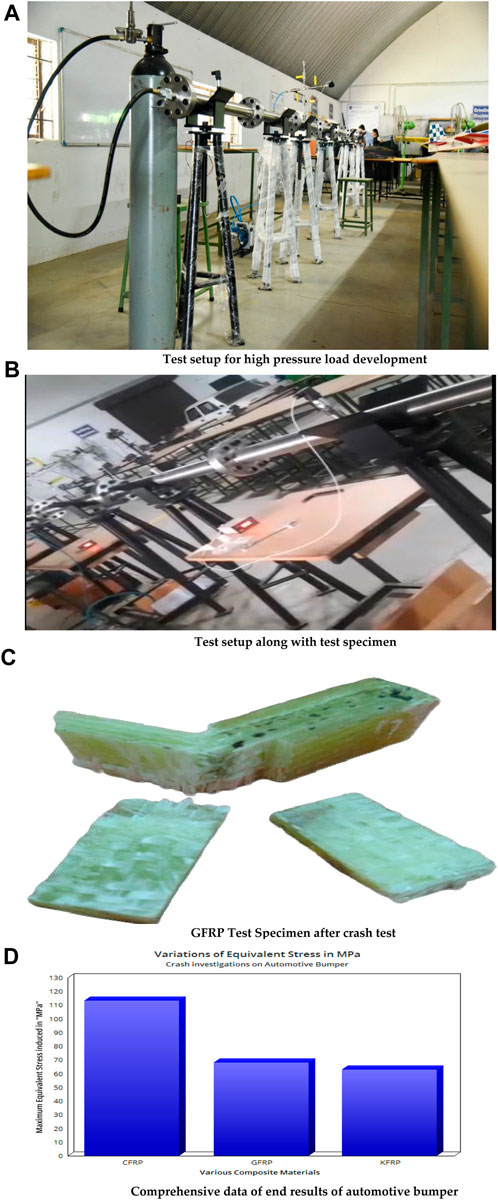
FIGURE 16. (A) Test setup for high-pressure load development. (B) Test setup along with the test specimen. (C) GFRP test specimen after the crash test. (D) Comprehensive data of the end results of the automotive bumper.
The experimental tests are conducted under normal atmospheric conditions outside and high-pressurized conditions inside the jet-path. The typical experimental test setup along with the test specimen is shown in Figure 16B, and after the test impacts, the broken GFRP test species are shown in Figure 16C.
The error percentage obtained is within the limit, which provided the green signal to extend the explicit-based crash investigation to other primary composite materials. Finally, the computational crash analysis is carried out on all the major three composite materials. The comprehensive end outcomes are given in Figure 16D.
4 Conclusion
The conventional and advanced impact computational investigations are computed with the help of ANSYS Workbench 17.2. The experimental outcomes are matched with these attained computational outcomes. From conventional computations, the following observations are noted: the E-GFRP-woven and KFRP-UD-49-based PMCs failed to react reasonably under the impact load, so these materials are unfit to provide a high lifetime for impact load-based real-time applications. The CFRP-UD-wet and S-GFRP-UD are the materials picked as the best performers and also suggested for use in complicated applications. Thus, these two aforesaid materials are underwent other complicated impact investigations, which are explained in the forthcoming sections.
The crash investigations are carried out, in which the conceptual design, composite construction, and crash analysis played a vital role. In the conceptual design phase, the barrier and moving object’s designs are primarily executed with the help of the ANSYS DesignModeler. In the composite preparation phase, the various fibers such as carbon fiber, glass fiber, and Kevlar fiber are implemented. The epoxy resin is also a commonly used matrix for all the cases. Finally, three different composite models are generated, and the properties are transferred using the ANSYS composite pre-processor. The material property of the barrier is extracted from the FEA numerical tool, in which steel is most commonly used. Lastly, the composite analyses are executed with the help of an explicit technique in the FEA numerical tool, in which the Kevlar-based composite is affected with low normal stress; therefore, comparatively, Kevlar is fit to handle impact load in an effective manner. As per the weight data, the KFRP is 37.68% lighter than the GFRP and 05.15% lighter than the CFRP. So, the KFRP is fit to generate lightweight components with high-impact resisting loads than any other lightweight materials. Through this multidisciplinary optimization, it is found that the KFRP performed better, in which the stress reduced in the KFRP is 2.85 times lighter than in the GFRP and 0.87 times lighter than in the CFRP. Thus, the KFRP is a better composite for withstanding any kind of complicated dynamic loading environments. The finalized advanced computational technique is validated, and so it can be extended to other complicated applications such as high-payload unmanned aircrafts, large main rotors and drone propellers, and tail rotary of rotary wing UAVs.
Data availability statement
The original contributions presented in the study are included in the article/Supplementary Material; further inquiries can be directed to the corresponding authors.
Author contributions
RG—experimental tests and investigations; BS—literature survey; VR—conceptualization, investigation, and original draft preparation; HA-B—original draft preparation; PR—original draft preparation, project guidance, and funding supports; JR—reviewing and editing the draft; SE—funding supports; VN—original draft preparation.
Funding
This work was partially funded by the research center of the Future University in Egypt, 2023.
Acknowledgments
The authors would like to thank the Department of Aeronautical Engineering, Kumaraguru College of Technology, Coimbatore—641049, Tamil Nadu, India, for providing the facility to carry out this research work.
Conflict of interest
The authors declare that the research was conducted in the absence of any commercial or financial relationships that could be construed as a potential conflict of interest.
Publisher’s note
All claims expressed in this article are solely those of the authors and do not necessarily represent those of their affiliated organizations, or those of the publisher, the editors, and the reviewers. Any product that may be evaluated in this article, or claim that may be made by its manufacturer, is not guaranteed or endorsed by the publisher.
References
Aruchamy, K., Subramani, S. P., Palaniappan, S. K., Pal, S. K., Mylsamy, B., and Chinnasamy, V. (2022). Effect of blend ratio on the thermal comfort characteristics of cotton/bamboo blended fabrics. J. Nat. Fibers 19 (1), 105–114. doi:10.1080/15440478.2020.1731903
Balakrishnan, K., Sharma, A., and Ali, R. (2017). Comparison of explicit and implicit finite element methods and its effectiveness for drop test of electronic control unit. Procedia Eng. 173, 424–431. doi:10.1016/j.proeng.2016.12.042
Belingardi, G., and Obradovic, J. (2011). Numerical crash analysis of composite racing car front impact attenuator by use of explicit FEM codes. Appl. Mech. Mater. 82, 290–295. doi:10.4028/www.scientific.net/AMM.82.290
Bhagavathiyappan, S., Balamurugan, M., Rajamanickam, M., Vijayanandh, R., Raj Kumar, G., and Senthil Kumar, M., Comparative computational impact analysis of multi-layer composite materials, AIP Conf. Proc., 2270, 040007, (2020), 1–5. doi:10.1063/5.0019380
Boria, S., and Belingardi, G. (2012). Numerical investigation of energy absorbers in composite materials for automotive applications. Int. J. Crashworthiness 17 (4), 345–356. doi:10.1080/13588265.2011.648516
Bussadori, B. P., Schuffenhauer, K., and Scattina, A. (2014). Modelling of CFRP crushing structures in explicit crash analysis. Compos. Part B Eng. 60, 725–735. doi:10.1016/j.compositesb.2014.01.020
Buyuk, M., Kan, S., and Loikkanen, M. J. (2009). Explicit finite-element analysis of 2024-T3/t351 aluminum material under impact loading for airplane engine containment and fragment shielding. J. Aerosp. Eng. 22, 287. doi:10.1061/(asce)0893-1321(2009)22:3(287)
Caputo, F., De Luca, A., Greco, A., Maietta, S., Marro, A., and Apicella, A. (2017). Investigation on the static and dynamic structural behaviors of a regional aircraft main landing gear by a new numerical methodology. Frat. Ed. Integrità Strutt. 12 (43), 191–204. doi:10.3221/IGF-ESIS.43.15
Javadova, H. A., Javadova, E. M., Ramazanova, Y. B., Yusifova, A. R., Mammadova, A. K., Shamilzadeh, T. I., et al. (2022). Developing lubricating compositions for lokomotive and industrial diesel engines on the basis of regenerated products. New Mater. Compd. Appl. 6 (1), 55–61.
Kesavan, K., Kiran, P., Sivaguru, M., Indira Prasanth, S., Sudharsan, R., Raj Kumar, G., et al. (2021). Multi-objective structural analysis of kevlar fiber reinforced polymer composite. Recent Adv. Smart Manuf. Mater. Lect. Notes Mech. Eng. 11, 137–151. doi:10.1007/978-981-16-3033-0_13
Kumar, A. M., Parameshwaran, R., Kumar, P. S., Pal, S. K., Prasath, M. M., Krishnaraj, V., et al. (2017). Effects of abaca fiber reinforcement on the dynamic mechanical behavior of vinyl ester composites. Mater. Test. 59 (6), 555–562. doi:10.3139/120.111044
Li, Q-M., Yi, Z-W., Liu, Y-Q., Tang, X-F., Jiang, W., and Li, H-J. (2022). Explicit analysis of sheet metal forming processes using solid-shell elements. Metals 12 (1), 52. doi:10.3390/met12010052
Matzenmiller, A., and Karl, S. (1991). Crashworthiness analysis of composite structures - a first step with explicit time integration, nonlinear computational mechanics: State of the art. Springer, 1–29.
Mori, L. F., Lee, S., Xue, Z. Y., Vaziri, A., Queheillalt, D. T., Dharmasena, K. P., et al. (2007). Deformation and fracture modes of sandwich structures subjected to underwater impulsive loads. J. Mech. Mater. Struct. 2 (10), 1981–2006. doi:10.2140/jomms.2007.2.1981
Murvatov, F. T., Usubaliyev, B. T., Mammadova, N. I., and Karimova, A. G. (2022). Development of nanostructured composite compound for impact on the bottomhole area (Ba) in utilization wells for the management of produced water (on the siyazan field example). New Mater. Compd. Appl. 6 (2), 119–126.
Mylsamy, B., Palaniappan, S. K., Subramani, S. P., Pal, S. K., and Sethuraman, B. (2020). Innovative characterization and mechanical properties of natural cellulosic Coccinia Indica fiber and its composites. Mater. Test. 62 (1), 61–67. doi:10.3139/120.111451
Nagappan, S., Subramani, S. P., Palaniappan, S. K., and Mylsamy, B. (2022). Impact of alkali treatment and fiber length on mechanical properties of new agro waste Lagenaria Siceraria fiber reinforced epoxy composites. J. Nat. Fibers 19 (13), 6853–6864. doi:10.1080/15440478.2021.1932681
Naveen Kumar, K., Meenakshi, S., Deviparameswari, K., Vaidegi, R., Nandhagopal, R., Ramesh, M., et al. (2021). “Investigation of energy generation on large rotary wing unmanned aerial vehicle’s propeller using coupled engineering approaches,” in Advances in environment engineering and management. Springer proceedings in earth and environmental sciences. Editors N. A. Siddiqui, K. D. Bahukhandi, S. M. Tauseef, and N. Koranga (Cham: Springer), 209–224.
Palaniappan, S. K., Pal, S. K., Rathanasamy, R., Kaliyannan, G. V., and Chinnasamy, M. (2020). “Experimental investigations in the drilling of hybrid fiber composites,” in Hybrid fiber composites. Editors A. Khan, S. M. Rangappa, M. Jawaid, S. Siengchin, and A. M. Asiri doi:10.1002/9783527824571.ch4
Raj Kumar, G., Balasubramaniyam, S., Senthil Kumar, M., Vijayanandh, R., Raj Kumar, R., and Varun, S. (2019). Crash analysis on the automotive vehicle bumper. Int. J. Eng. Adv. Technol. 8 (6S3), 1602–1607. doi:10.35940/ijeat.F1296.0986S319
Raja, V., Balaji, S., Raj Kumar, G., Naveen Kumar, K., Jagadeeshwaran, P., Arul Prakash, R., et al. (2022). “Structural optimizations of different load-carrying members based on low structural performance through computational structural analysis: Structural optimizations of sandwich composite through FEA approach,” in Handbook of research on advancements in the processing, characterization, and application of lightweight materials. IGI global. Editor K. k. Kumar, 262–286.
Ramesh, M., Vijayanandh, R., Jagadeeshwaran, P., Deviparameswari, K., Meenakshi, S., Asher, P., et al. (2022). Impact behavioral studies on various composite materials using Fluid-Structure interaction (FSI). Mater. Today Proc. 51, 1134–1140. doi:10.1016/j.matpr.2021.07.112
Sharaf, H. K., Alyousif, S., Khalaf, N. J., Hussein, A. F., and Abbas, M. K. (2022). Development of bracket for cross arm structure in transmission tower: Experimental and numerical analysis. New Mater. Compd. Appl. 6 (3), 257–275.
Smojver, I., and Ivančević, D. (2017). Application of numerical methods in the improvement of safety of aeronautical structures. Transp. Res. Procedia 28, 164–172. doi:10.1016/j.trpro.2017.12.182
Swati, R. F., Amjad, M. A. Y., Talha, M., Elachi, H., Hamdani, H. R., Khan, A. A., et al. (2022). Crashworthiness study of UCAV’s main landing gear using explicit dynamics. Int. J. Crashworthiness 27 (6), 1843–1859. doi:10.1080/13588265.2022.2028449
Tanay Topac, O., Gozluklu, B., Gurses, E., and Coker, D. (2017). Experimental and computational study of the damage process in CFRP composite beams under low-velocity impact. Compos. Part A Appl. Sci. Manuf. 92, 167–182. doi:10.1016/j.compositesa.2016.06.023
Vijayanandh, R., Raj Kumar, G., Arul Prakash, R., Senthil Kumar, M., Indira Prasanth, S., Kesavan, K., et al. (2022). “Optimizations on various lightweight composite materials under complex load using advanced computational simulation,” in Hybrid composites: Processing, characterization, and applications. Editors K. Kumar, and B. Babu (Berlin, Boston: De Gruyter), 81–102.
Yan, M., and Wang, T. (2012). “Finite element analysis of cylinder piston impact based on ANSYS/LS-DYNA,” in Proceedings of the 1st international conference on mechanical engineering and material science, advances in intelligent systems research, 107–110. doi:10.2991/mems.2012.66
Zhang, Y., Wang, B., Ning, Y., Xue, H., and Lei, X. (2022). Study on health monitoring and fatigue life prediction of aircraft structures. Materials 15 (23), 8606. doi:10.3390/ma15238606
Zhou, Y., Sun, Y., and Huang, T. (2020). Bird-strike resistance of composite laminates with different materials. Materials 13 (1), 1–22. doi:10.3390/ma13010129
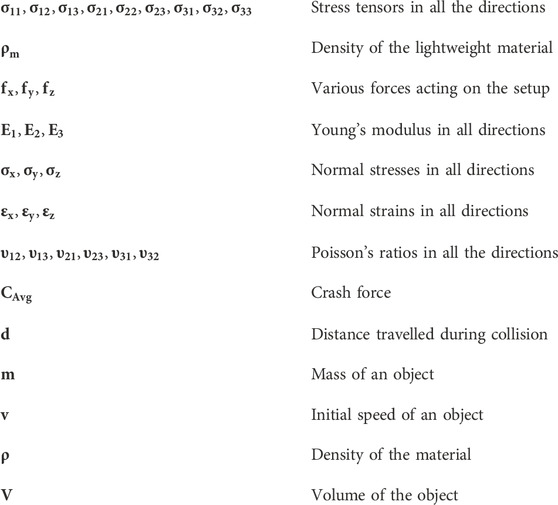
Nomenclature
Keywords: bullet, bumper, composites, crash investigation, explicit dynamics, impact strength, UAV’s propeller
Citation: Gnanasekaran RK, Shanmugam B, Raja V, Al-Bonsrulah HAZ, Rajendran P, Radhakrishnan J, Eldin SM and Narayanan V (2023) Comprehensive computational investigations on various aerospace materials under complicated loading conditions through conventional and advanced analyses: a verified examination. Front. Mater. 10:1147310. doi: 10.3389/fmats.2023.1147310
Received: 18 January 2023; Accepted: 15 March 2023;
Published: 04 May 2023.
Edited by:
Natrayan L., Saveetha University, IndiaReviewed by:
Prabhu Paramasivam, Mettu University, EthiopiaSathish Kumar Palaniappan, King Mongkut’s University of Technology North Bangkok, Thailand
Santhosh M. S., Anna University, India
Copyright © 2023 Gnanasekaran, Shanmugam, Raja, Al-Bonsrulah, Rajendran, Radhakrishnan, Eldin and Narayanan. This is an open-access article distributed under the terms of the Creative Commons Attribution License (CC BY). The use, distribution or reproduction in other forums is permitted, provided the original author(s) and the copyright owner(s) are credited and that the original publication in this journal is cited, in accordance with accepted academic practice. No use, distribution or reproduction is permitted which does not comply with these terms.
*Correspondence: Parvathy Rajendran, YWVwYXJ2YXRoeUB1c20ubXk=; Sayed M. Eldin, c2F5ZWQuZWxkaW4yMkBmdWUuZWR1LmVn