 Xinyu Liu1
 Junjun Wang
95% of researchers rate our articles as excellent or good
Learn more about the work of our research integrity team to safeguard the quality of each article we publish.
Find out more
ORIGINAL RESEARCH article
Front. Mater. , 07 February 2023
Sec. Environmental Degradation of Materials
Volume 10 - 2023 | https://doi.org/10.3389/fmats.2023.1145631
This article is part of the Research Topic Protective Coatings in Harsh Environments View all 5 articles
Introduction: Recently, great efforts have been dedicated to tailoring the microstructure of the RHEA films to further optimize the performance of the films. However, there is still a lack of in-depth study on their wear mechanism and microstructure evolution.
Methods: In this work, the novel ZrNbTiMo RHEA films were prepared by DC magnetron sputtering and splicing target techniques. The effects of sputtering power on the microstructure, hardness, toughness, and wear resistance of ZrNbTiMo RHEA films were investigated in detail.
Results: The ZrNbTiMo films possess the nanocomposite structure, the bcc nanocrystal is wrapped in an amorphous phase. The wear resistance of the film is expected to be improved by finding an appropriate ratio between the amorphous phase and the nanocrystal phase. The nanocrystal structure ensures the high hardness (6.547 ∼ 7.560 GPa) of the ZrNbTiMo film. In addition, the nanocrystals hinder crack propagation, this toughness mechanism effectively improves the toughness of the film. The ZrNbTiMo film prepared at 150 W possesses excellent mechanical properties, hardness of 7.240 GPa and toughness of 0.437 ± 0.040 MPa × m1/2, exhibits better wear resistance (wear rate: 5.223 × 10⁻⁷ mm3/N m).
Discussion: The wear resistance of ZrNbTiMo film is controlled by both hardness and toughness. The nanocomposite structure makes the ZrNbTiMo films possess a composite fracture which could improve the toughness of the ZrNbTiMo film. The wear-resistant ZrNbTiMo RHEA films with wear rates of the order of 10−6 mm3/N m have been prepared by tuning the sputtering power, this film can be used as a potential candidate for wear-resistant coatings.
Friction and wear are common phenomena in the service process of moving parts (Holmberg and Erdemir, 2019). Wear resistance is important in determining the component’s service life. The wear phenomenon mainly occurs on the surface of components. Therefore, it is an economically feasible method to deposit high-performance film material on the surface of low-cost components. High-entropy alloy (HEA) films (Yeh et al., 2004; Song et al., 2020), as a novel alloy film material, inherit the excellent properties of the bulk HEA, such as superior strength (Wu et al., 2018; Chung et al., 2019; Tong et al., 2019), high hardness (Alvi et al., 2020; Huang et al., 2020), high ductility (Li et al., 2016; Li et al., 2017), outstanding oxidation, wear and fracture resistance (Hemphill et al., 2012; Liu et al., 2019; Lee et al., 2021; Liao et al., 2023). In addition, refractory high-entropy alloy (RHEA) films (Senkov et al., 2010) are composed of high melting point elements of 4, 5, and 6 subfamilies and could be used as heat- or wear-resistant coatings.
Magnetron sputtering (MS) is one of the most used techniques for the preparation of RHEA films with nanocrystal structure which exhibit a significantly higher hardness than their bulk counterpart (Alvi et al., 2020). In addition, by adjusting the parameters of the magnetron sputtering process, the microstructure of the RHEA films can be affected and further optimizes the performance (Kim et al., 2019a; Kim et al., 2019b). For the RHEA films used in wear resistance applications, toughness is another mechanical performance index that should not be ignored. However, the improvement of film toughness has been a technical challenge for material scientists and engineers (Zhang and Zhang, 2012; Zhang et al., 2017; Liu et al., 2021). A study by Yue et al. (2022) showed that finding an appropriate ratio between the amorphous phase and the nanocrystal phase is expected to lead to highly wear-resistant films. On the one hand, the amorphous structure will hinder the nanocrystal from plastic deformation, on the other hand, the nanocrystal will hinder the shearing of amorphous regions. Recently, great efforts have been dedicated to tailoring the crystalline phase structure of the RHEA films to improve the mechanical properties of the films by adjusting the deposition parameters. Song et al. (2019) found that the diffusion ability of deposited atoms in the TaNbHfZr film is improved by increasing the substrate temperature in the magnetron sputtering process, the microstructure of the film transforms from the amorphous structure at a deposition temperature of 25°C to BCC crystal structure at 700°C. Feng et al. (2017) prepared the NbMoTaW films of different thicknesses by controlling deposition time. The increase in deposition time promotes the increase of the atoms’ diffusion time, thus ensuring the growth of grains. Wang et al. (2021) emphasized that changing deposition power can tailor both the diffusion ability and the available time of the deposited atom simultaneously. The structures of the CoNiVAl films change from an amorphous structure to a crystalline structure, and the hardness and tensile strength of the film increase monotonically with the increase of sputtering power. However, research on the effect of sputtering power on the wear resistance of the RHEA films is still rare and needs to be explored in detail.
In this work, we developed a novel ZrNbTiMo RHEA film. The elements of the film were selected as follows: Nb and Mo enhance the hardness and wear resistance (Tao et al., 2018; Yu et al., 2019), and Ti and Zr improve the tensile properties and toughness of the RHEA (Han et al., 2017; Chen et al., 2022). The sputtering power ranging from 90 to 210 W was applied to investigate its effects on the microstructure, mechanical properties, and tribological properties of the ZrNbTiMo film in detail. The growth mechanism of nanocrystals in the film was analyzed from the perspective of atom deposition. The toughening mechanism and the wear resistance mechanism of the ZrNbTiMo film were investigated from the microstructure perspective in detail.
The ZrNbTiMo HEA films were deposited on polished ASTM304 (30 × 30 × 1.5 mm3) and Si (100) wafer (50 × 10 × 0.7 mm3) by direct-current magnetron sputtering. The splicing target (Φ 76.2 × 5 mm2) consists of four 90° fan-shaped Zr, Nb, Ti, and Mo (99.95% purity) targets. During deposition, the Ar was filled at 100 sccm to ensure a constant work pressure of 0.8 Pa. The target-to-substrate distance was fixed at 100 mm, the substrate holder rotated at a speed of 10 r/min and the substrate bias voltage was maintained at −50 V. The sputtering power varied from 90 to 210 W (step size: 30 W), and the film thickness was controlled to 1.0 ± 0.1 µm by adjusting the deposition time. After the deposition process, the films were kept in a vacuum chamber and cooled to room temperature before taking out to minimize oxidation.
The surface and cross-sectional morphologies were observed by field emission scanning electron microscopy (FESEM, ΣIGMA HDTM, ZEISS, Germany). An energy dispersive spectrometer (EDS, X-Max 20, Oxford, Britain) integrated into the FESEM was used to measure the chemical composition of the films. The crystal structure and phase composition of the ZrNbTiMo films were analyzed by a glancing incident X-ray diffraction (GIXRD, Empyrean Series2, PANalytical, Britain) with Cu-Kα radiation (λ = 1.5405 nm) and an incident angle of 0.5°, the scanning angle (2θ) ranged from 20° to 90° at a scanning speed of 4°/min. The crystallite size of the ZrNbTiMo films is calculated by the Scherrer equation d = kλ/βcosθ, where d is the average crystallite size, k is the shape factor, and β is the full width at half-maximum. The interplanar spacing of films is calculated according to Bragg equation 2dsinθ = λ, where d is interplanar spacing, θ is diffraction angle and λ is X-ray wavelength. The nanostructure of the ZrNbTiMo film was analyzed by transmission electron microscopy (TEM, Titan Themis 200, FEI, America). The TEM samples with a Pt protective layer were prepared by a focused ion beam system (Helios 450 S dual beam, FEI, America).
The elastic modulus (E) and hardness (H) of films were characterized by a nano-indentation tester (Nano-Indenter G200, KLA, America) equipped with a standard Berkovich diamond indenter under continuous stiffness mode, the indentation depth was maintained within 90 nm to avoid the influence of the substrate, the elastic modulus and hardness of each sample were measured at six points to ensure the data reliability. The residual stress (σ) of the films deposited on the Si (100) wafers was characterized by a film stress tester (FST-1000, Supro Instruments, China), the residual stress was calculated by the Stoney formula, as shown in Eq. 1:
where Es is the elastic modulus and Vs is Poisson’s ratio of the substrate, hs and hf are the thickness of substrate and film respectively, and R1 and R2 are the curvature radii of the sample before and after deposition, respectively. The crack resistance of the ZrNbTiMo films was detected by a Vickers hardness tester (HVS-1000Z, Shanghai Yi Zong Precision Instrument Co., China) with a load of 1 N for 15 s, and the indentation morphology was observed by FESEM. The fracture toughness (KIC) was calculated according to Eq. 2:
where P is the load, E is the elastic modulus, H is the hardness, and c is the radial crack length, which was obtained by calculating the average value of crack length from five indentations. During the adhesion strength test, a diamond tip contacted the film’s surface, and a 1 N load was applied, then the diamond tip slides forward 10 mm at a sliding speed of 40 mm/min, and the contact load linearly increased to 30 N. The critical load (Lc) at which the film first delamination on the trackside was recorded.
The tribological properties of the ZrNbTiMo films were evaluated by tribometer (UMT-TriboLab, Bruker, America) under the linear reciprocating mode, the friction test was conducted under a constant load of 2 N and frequency of 2 Hz condition for 30 min. The friction counterpart was a Si3N4 ball with a diameter of 6 mm and the length of the wear tracks was 10 mm. After the test, the surface morphology of wear tracks was observed via a tungsten filament scanning electron microscopy (JCM-7000, JEOL, Japan). The cross-sectional area of the wear tracks was obtained by a white light interferometer (Contour GT-K, Bruker, America), and the wear rate (W) of the ZrNbTiMo films was calculated by Eq. 3:
where V is the wear volume of the wear track, L is the applied constant load and S is the sliding distance.
The element concentration of the ZrNbTiMo RHEA films deposited at different sputtering power is shown in Figure 1A. The element concentration of Mo, Zr, Nb, and Ti in the films deviates slightly from that in the splicing target. The atom ratio of three elements (Ti, Zr, and Nb) in the RHEA film is near-equal and the concentration of each element is between 15 and 25 at%, the Mo element concentration is significantly higher than that of the other three elements. The difference in the element concentration is attributed to the sputtering yield specific to each element (Yamamura and Tawara, 1996). Under the normal incidence of Ar+ (energy: 300 eV), the sputtering yields of Ti, Zr, Nb, and Mo are 0.465, 0.463, 0.592, and 0.652 (Zhang et al., 2022). The number of atoms deposited on the film surface is positively correlated with their sputtering yield. Figure 1B shows the SEM image of the ZrNbTiMo RHEA film deposited at 150 W which is imaged by backscattered electron signal (BES), the corresponding element distribution maps are shown in Figure 1C. All alloy elements are uniformly distributed in the micron-scale region, which means the splicing target is a technically feasible method to prepare the RHEA film with uniform composition distribution. The adjustment of the element content will be more flexible by changing the fan-shaped area of the splicing target, which effectively solves the challenge of preparing the cast RHEA target.

FIGURE 1. (A) Elemental concentration of the ZrNbTiMo films deposited at different sputtering power, (B) SEM image, and (C) element mapping images of the top surface of the film deposited at 150 W.
The morphologies of the surface and cross-section of the films deposited at different sputtering power are shown in Figure 2. The ZrNbTiMo RHEA film has a relatively smooth island-like structure at 90 W sputtering power. Many triangular conical protrusion structures occur on the film surface with the power increasing to 120 and 150 W. As the power increases to 210 W, the surface changes to a smooth island-like structure again. The dependence between the film’s cross-sectional structure and sputtering power is also obvious. The cross-sectional structure of the film changes gradually from a fine fiber structure at 90 W to a columnar grain structure at 150 W, then transforms into a fine fiber structure at 210 W finally.
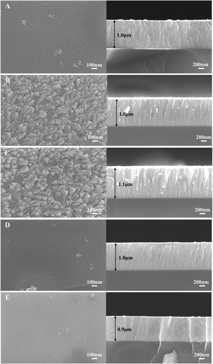
FIGURE 2. SEM images of the surface and cross-section of the ZrNbTiMo RHEA films deposited at different sputtering power: (A) 90 W, (B) 120 W (C) 150 W, (D) 180 W, and (E) 210 W.
The phase formation ability of HEA can be predicted by thermodynamic parameters, the mixing enthalpy (ΔHmix), atom size difference (δ), and mixing entropy (ΔSmix) of ZrNbTiMo were listed in Table 1. The thermodynamic parameters of ZrNbTiMo are consistent with the theoretical formation condition of solid-solution phases (11 J/Kmol ≤ ΔSmix ≤ 19.5 J/Kmol, −22 kJ/mol ≤ ΔHmix ≤ 7 kJ/mol and 0% ≤ δ ≤ 8.5%). The valence electron concentration (VEC) is a decisive factor in the formation of the FCC or BCC solid solutions phase (Guo et al., 2011). The VEC values of ZrNbTiMo are less than 6.87, indicating the formation of the BCC phase in ZrNbTiMo. However, the actual microstructure for the ZrNbTiMo films is also controlled by the dynamic parameters during the deposition process. Therefore, the actual microstructure of ZrNbTiMo films needs to be explored. Figure 3 shows the XRD patterns of the ZrNbTiMo film prepared at different sputtering power. The films deposited at 120 and 150 W sputtering powers show clear diffraction peaks of (110) and weak diffraction peaks of (200), and (211), which confirms the existence of the BCC phase in the ZrNbTiMo RHEA films. For the diffraction peak of (110), a broad diffraction hump appears for other sputtering powers. In addition, the intensity of (200) and (211) diffraction peaks diminish gradually when the sputtering power decreases to 90 W or increases to 180 W, and (200) and (211) diffraction peaks disappear eventually at the sputtering power of 210 W. The average crystallite size and crystallinity of the ZrNbTiMo films are shown in Table 2. With the increase of sputtering power, the crystallinity experienced a process of first increasing and then decreasing, the optimized crystallinity (20.07%) of films is achieved at 150 W.
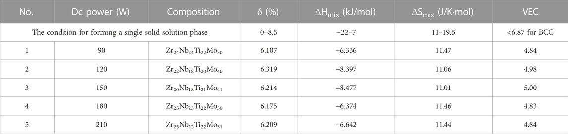
TABLE 1. The sputtering power, chemical composition, and thermodynamic parameters of the ZrNbTiMo RHEA films.
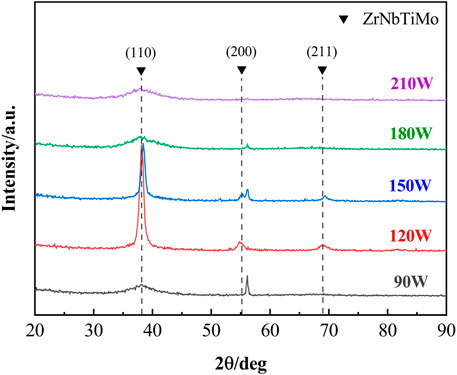
FIGURE 3. XRD patterns for the ZrNbTiMo RHEA films deposited at different sputtering power.
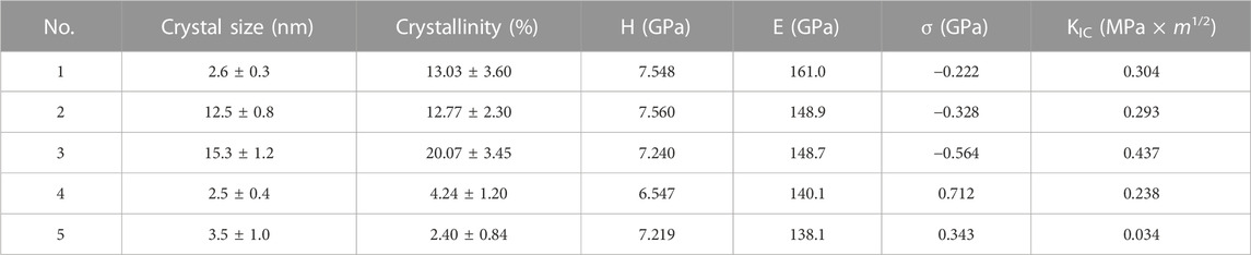
TABLE 2. The crystallite size, crystallinity, hardness (H), elastic modulus (E), residual stress (σ), and fracture toughness (KIC) of the ZrNbTiMo RHEA films.
TEM allows us to probe the microstructure and phase structure of the films at the nanometer scale. Here, the ZrNbTiMo RHEA films deposited by 150 and 210 W were selected for the TEM test. Figures 4A, D show the cross-sectional TEM images of the ZrNbTiMo RHEA films deposited by 150 and 210 W, respectively. From the selected area electron diffraction (SAED) patterns in Figures 4A, D, the diffused diffraction rings and bright diffraction spots indicate that the structure of the film is the nanocomposite structure, composed of two phases: a nanocrystalline phase and an amorphous phase (Kamalan Kirubaharan and Kuppusami, 2020). High-resolution TEM (HRTEM) images of the ZrNbTiMo RHEA films deposited at 150 and 210 W are shown in Figures 4B, E respectively. As shown in the inserted fast Fourier transform (FFT) images in Figure 4E, the amorphous structure accounts for a larger proportion in the 210 W film. Only a few ordered regions about 10–20 nm in diameter are embedded into the amorphous matrix. However, many ordered regions with size over 30 nm appeared in the 150 W film, the relatively more optimized crystallinity of the 150 W film is consistent with the more obvious diffraction peak in the XRD pattern. In addition, some (110) type planar defects (stacking faults) with different spaces (3–5 atomic width) are found in the nanocrystalline structure (Feng et al., 2018), as shown in Figure 4B. The crystal planes with an orientation of (110), (200), and (211) of the bcc phase are marked in Figure 4C. The spacing of the (110) crystal plane is 0.234 nm, which is consistent with the analysis results of the XRD pattern (0.233 nm). The crystal planes with an orientation of (110) and (200) of the bcc phase are marked in Figure 4F. The analysis results of the TEM test more intuitively prove that changing the sputtering power can effectively control the crystallinity and nanocomposite structure of the ZrNbTiMo films.
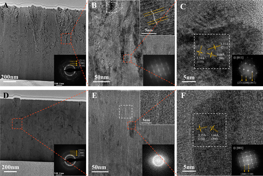
FIGURE 4. Cross-section microstructure of the ZrNbTiMo RHEA films: (A,D) TEM images with SAED patterns of the film deposited at 150 W and 210 W respectively, (B,E) magnified TEM images, (C,F) HRTEM images with FFT patterns corresponding the characteristic regions marked by the white rectangles.
Wang et al. (2021) have found that the nanocrystalline phase fraction in the HEA films experienced a process of first increasing and then decreasing with the sputtering power increasing. Such a microstructural change can be explained by the multiple competition between atom diffusion ability promoted by incident atom energy and available time limited by deposition rate. The incident atom energy can be expressed by Eq. 4:
where DW is the target power, Pg is the working pressure and VS is the substrate bias voltage. According to the equation, Uk is directly related to DW when the other parameters remain constant (Zhang et al., 2004). With the increase of the sputtering power from 90 to 150 W, the incident atom energy increases which promotes the migration of the deposited atom, leading to the growth of nanocrystalline and the increase of the film crystallinity. With the sputtering power increasing to 210 W, the number of atoms reaching at substrate surface per unit of time increases. The higher deposition rate means that the available time of deposited atoms’ re-arrangement before being buried by the additional incident atoms becomes shorter, which limits the atom diffusion ability, and the crystallinity of the film decreases.
The load-displacement curves of the ZrNbTiMo RHEA films deposited at different sputtering power are shown in Figure 5A. The hardness and elastic modulus of the film can be calculated according to Eqs. 5–7, and the analytic diagram is shown in the illustration of Figure 5A.
where H, Er, E, and ν are the hardness, reduced modulus, elastic modulus, and Poisson’s ratio of the RHEA film, respectively. Pmax is the load corresponding to maximum indentation depth. A is the projective area of the contact surface between the diamond indenter tip and the film under the load of Pmax. S is the elastic contact stiffness at Pmax calculated by the slope of the initial 30% unloading of the load-displacement curves (Oliver and Pharr, 2011). The H and E of the ZrNbTiMo RHEA films are shown in Figure 5B and Table 2. The Pmax of the films deposited at 90, 120, and 150 W are similar, these films possess similar hardness (7.3 ± 0.2 GPa). Moreover, the elastic contact stiffness (S) of the RHEA films monotonously decreases with the increase of sputtering power, and this change ultimately causes the elastic modulus of the film to decrease from 161.0 to 138.1 GPa. The high hardness of the films is attributable to the following two reasons: Firstly, according to the Hall-Petch effect, the grain boundary structure can effectively hinder dislocation motion, the ZrNbTiMo films with smaller grain size acquire a higher hardness than their bulk counterparts with larger grain size (Zou et al., 2017). Secondly, the high-entropy effect causes the nanocrystalline structures in the ZrNbTiMo films to form a single-phase solid solution structure. The remarkable solid solution strengthening due to sever lattice distortion causes the ZrNbTiMo RHEA films to exhibit higher hardness compared with the other elemental metal films, such as Nb (∼3 GPa), Mo (∼2 GPa), and Ti (∼5 GPa) films (Vieira et al., 2002; Schneider et al., 2009; Kaufmann et al., 2013).
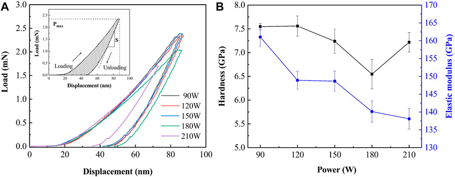
FIGURE 5. (A) Load-displacement curve with an analysis schematic diagram in the illustration and (B) hardness and elastic modulus of the ZrNbTiMo RHEA films deposited at different sputtering power.
Figure 6 shows the residual stress of the ZrNbTiMo films deposited at different sputtering power. The compressive residual stress increases with a concurrent increase in the sputtering power from 90 to 150 W, then the residual stress transforms into tensile residual stress with the sputtering power increasing to 180 and 210 W. This change can be explained from the aspect of the film microstructure. With the sputtering power increasing from 90 to 150 W, the diffusion ability of deposited atoms improves, and the film cross-sectional structure changes from a fine fiber structure to a columnar grains structure with a larger grain size. As the size of columnar grains increases, adjacent columnar crystals squeeze against each other causing increasing compressive residual stress. With the sputtering power further increasing to 180 and 210 W, the films exhibit the fine fibrous cross-sectional structure again. The diffusion ability of deposited atoms is limited, the gaps appear between the fine fibrous grains. However, due to the mutual attraction between the atoms of adjacent fine fibrous grains, the gaps disappear and change to grain boundaries which leads to the tensile residual stress (Thornton and Hoffman, 1989).
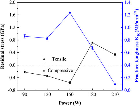
FIGURE 6. Residual stress and fracture toughness of the ZrNbTiMo RHEA films deposited at different sputtering power.
Figure 7 shows the Vickers indentation morphologies of the ZrNbTiMo RHEA films deposited at different sputtering power. In general, the fracture toughness (KIC) of the films is inversely proportional to the radial crack length (Zhang et al., 2017). The fracture toughness of the ZrNbTiMo RHEA films is shown in Figure 6, the film deposited at 150 W possesses the maximum toughness. This may be attributed to two main factors: microstructure and compressive residual stress. Firstly, according to Chakraborty et al. (2009), (Zhu et al., 2011), the plastic metal phase in the amorphous matrix can work as a micro-energy absorber and a bridge connecting the amorphous matrix during the plastic deformation process of composite coatings, thus buffering and deflecting the crack propagation. Therefore, the nanocrystalline in the film will lead to the mixed fracture mode, in which the trans-granular fracture mode dissipates energy via nanocrystalline plastic deformation and the intergranular fracture mode dissipates energy by increasing the crack length. What’s more, for the trans-granular fracture mode, the existence of stacking fault structures in nanocrystals of the 150 W films could further hinder the dislocation movement. Secondly, the compressive residual stress of the film will promote the closure of microcracks which hinders the propagation of cracks (Yu et al., 2021), the toughness correspondingly increases as the compressive residual stress increases. Hence, the 150 W film exhibits the maximum fracture toughness, the toughening mechanism of the 150 W film can be described as shown in Figure 8.
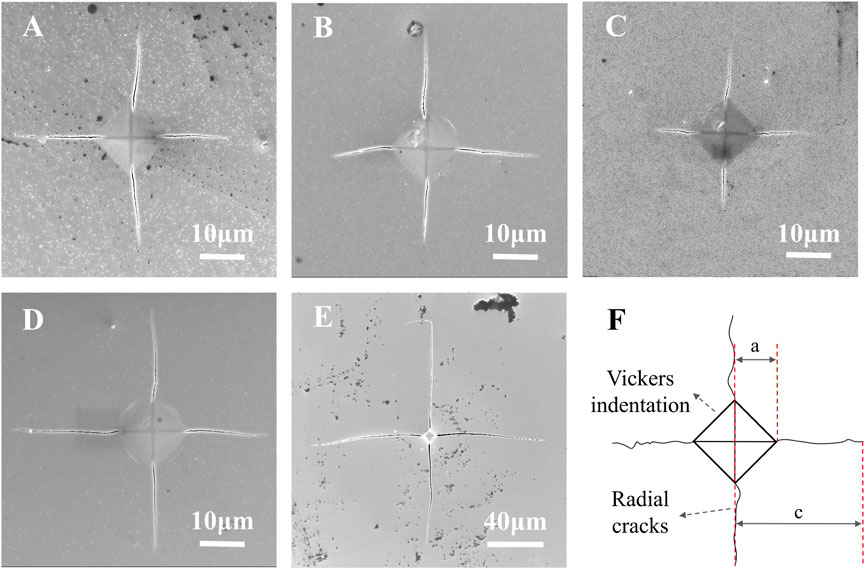
FIGURE 7. Vickers indentation morphologies of the ZrNiTiMo RHEA films on Si substrate deposited at different sputtering power: (A) 90 W, (B) 120 W, (C) 150 W, (D) 180 W, (E) 210 W, and (F) an illustration of radial cracks.
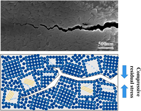
FIGURE 8. Magnification image of crack and the schematic diagram of the toughening mechanism corresponding to the ZrNbTiMo RHEA films deposited at 150 W.
The adhesion between film and substrate is another important factor affecting the wear resistance of the films. Figure 9 shows the surface morphologies of the scratch tracks for different films at critical loads. In Figures 9B, C, the 120 and 150 W films exhibit slight splits with minor exfoliation along both sides of the scratches. For the 90 and 180 W films, similar morphologies appear at shorter sliding distances, as shown in Figures 9A, D, whereas the 210 W film exhibits a large area of film exfoliation on the surface of the scratches, as shown in Figure 9E. The critical load values obtained from scratch measurements are 9.7, 16.0, 12.2, 3.9, and 3.1 N for the films deposited by 90, 120, 150, 180, and 210 W respectively, the film deposited at 210 W possesses the poorest adhesion compared with other films. Two notable reasons which determine the poorest adhesion of the 210 W film are tensile residual stress and toughness: Firstly, lower toughness means that the film’s ability to absorb energy during the plastic deformation is limited and the film is easier to fracture. Secondly, tensile stress in the film can cause the rapid propagation of cracks and may lead to the film separating from the substrate finally. The ZrNbTiMo thin films deposited by 120 and 150 W power are expected to have better wear resistance than other films due to their excellent performance combination of hardness, toughness, and adhesion. We further confirm the wear resistance of the ZrNbTiMo film in the following section.
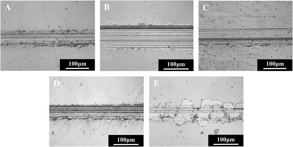
FIGURE 9. Surface morphologies of the scratch tracks for the ZrNbTiMo RHEA films deposited at different sputtering power: (A) 90 W, (B) 120 W, (C) 150 W, (D)180 W, and (E) 210 W.
The tribological properties of the ZrNbTiMo films were evaluated using a tribometer under the linear reciprocating mode. The friction coefficient curves of the ZrNbTiMo films deposited at different sputtering power are shown in Figure 10A. During the test, a running-in stage is observed corresponding to the initial transient followed by a sudden increase in the friction coefficient. After the running-in stage, the friction coefficient of the ZrNbTiMo films remained stable at approximately 0.65. The friction coefficient curve of the film deposited by 150 W is relatively stable and smooth, while the friction coefficient curve fluctuates between 0.5 and 0.7 for the film deposited by 180 and 210 W. The friction coefficient curve may fluctuate due to the irregular surface morphology caused by the wear debris particles, plastic deformation, and pits.
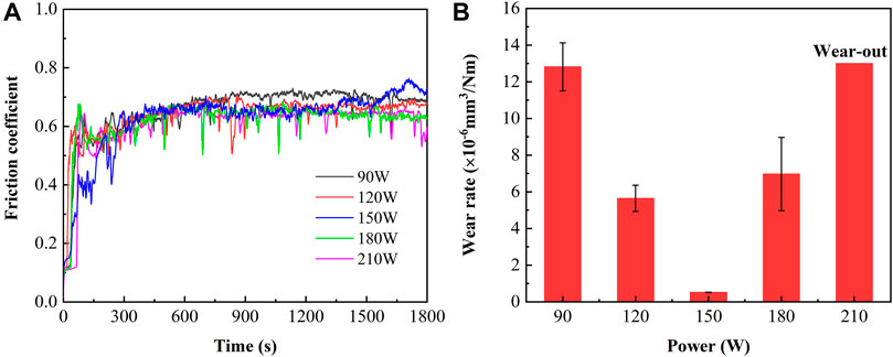
FIGURE 10. (A) Friction coefficient curve and (B) wear rate of the ZrNbTiMo RHEA films deposited at different sputtering power.
The morphology of the worn area was imaged by a white light interferometer to calculate the wear rate of the ZrNbTiMo films. As shown in Figure 10B, the wear rate value is 12.933 × 10⁻⁶, 6.091 × 10⁻⁶, 0.522 × 10⁻⁶, and 6.972 × 10⁻⁶ mm3/N m for the films deposited by 90, 120, 150, and 180 W respectively, the film deposited by 210 W is worn out. The film deposited by 150 W exhibits the best wear resistance. The film wear track morphology of the selected films deposited by 150 and 210 W was used to analyze the wear mechanism, as shown in Figure 11 and Figure 12 respectively. For the film deposited at 150 W, in Figures 11A, B, the furrow parallel to the wear track was observed and the slight film peeling phenomenon occurred on the film surface, resulting in the maximum depth of wear tracks exceeding the film thickness in individual areas (up to 1.3 µm), which proves the abrasive wear mechanism for the 150 W film. The high-magnification image (Figures 11C, D) shows that fatigue cracks occur on the film surface due to repeated plastic deformation during reciprocating friction. The accumulation of cracks causes delamination and spalling of local film, resulting in the fatigue wear mechanism. For the film deposited by 210 W, Figures 12A, B exhibits the furrow parallel to the wear track, and the depth exceeds the film thickness to 4.6 μm. The high magnification image (Figure 12C) shows that a large area of film peeling appeared at the edge of the wear track. The element distribution corresponding to this wear track is shown in Figure 12D, the element content of Fe in the film peeling area increases obviously, indicating that the film has been worn out and the ASTM304 substrate exposed. The wear mechanism of the 210 W film is severe abrasive wear.
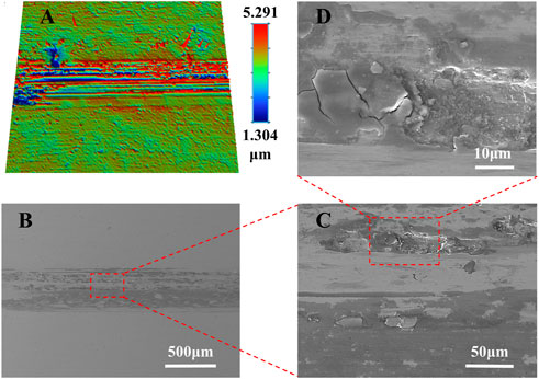
FIGURE 11. Wear surface of the ZrNbTiMo RHEA film deposited at 150 W: (A) 3D image; (B), (C), and (D) SEM image.
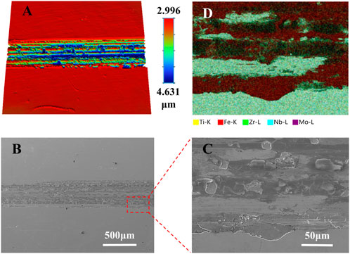
FIGURE 12. Wear surface of the ZrNbTiMo RHEA film deposited at 210 W: (A) 3D image; (B) and (C) SEM image; (D) Face-scan element distribution map of (C).
Wear is a complex process of material consumption, the process is affected by various mechanical properties, such as hardness, residual stress, fracture toughness, and adhesion. We found that fracture toughness is the significant factor affecting the wear resistance of the ZrNbTiMo RHEA films in our work. For the low toughness ZrNbTiMo film (the film deposited at 210 W), the plastic deformation occurs on the film surface when the friction pair contacts with the film and the microcracks appear due to the brittle characteristics of the film. During the reciprocating friction process, the microcracks eventually spread into the inner and penetrate the ZrNbTiMo films. Then, the cracks inside the film accumulate gradually leading to adjacent cracks connecting, which causes the decohesion of the film particles. These particles become wear debris in the abrasive wear process which further aggravates the generation of wear debris and microcracks, and severe abrasive wear occurs finally. The wear mechanism diagram is shown in Figure 13A. For the high toughness ZrNbTiMo films (the film deposited at 150 W), when the friction pair contacts with the film surfaces, due to the toughening mechanism of the nanocomposite structures, the nanocrystals in the films can alleviate the cracks propagating into the inner of the films. During reciprocating friction, the decrease in the number of cracks leads to an increase in the time for fatigue crack accumulation and a decrease in the crack length, reducing the size of hard abrasive particles. The damage to the film caused by abrasive wear could be relieved. Thus, the wear mechanism of the ZrNbTiMo film deposited by 150 W is mainly fatigue wear accompanied by slight abrasive wear, the wear mechanism diagram is shown in Figure 13B.
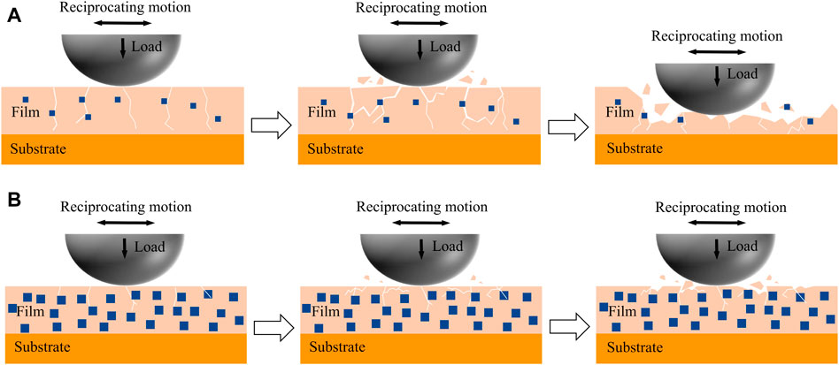
FIGURE 13. Schematic diagram about the wear mechanism of the ZrNbTiMo RHEA films deposited at (A) 210 W and (B) 150 W.
In this work, we have systematically investigated the effects of sputtering power on the microstructure, mechanical, and tribological properties of the ZrNbTiMo films. In addition, the toughening mechanism and wear mechanism of the ZrNbTiMo film were discussed in detail.
1) The elements of the ZrNbTiMo films prepared by splicing target are evenly distributed on a micron scale. The alloy element content of the ZrNbTiMo film can be adjusted more flexibly by changing the area of the splicing target.
2) All the ZrNbTiMo films possess a nanocomposite structure which is composed of two phases: A nanocrystalline phase and an amorphous phase. The film deposited at 150 W exhibits a larger crystallite size (15.3 nm) and more optimized crystallinity (20.07%).
3) The nanocomposite structure makes the ZrNbTiMo films possess a composite fracture mode that mixes the trans-granular fracture mode and the intergranular fracture mode, which eventually improves the toughness of the ZrNbTiMo film.
4) The hardness of the ZrNbTiMo films decreases with the increase of sputtering power. The film deposition by 150 W shows the maximum toughness (0.437 MPa × m1/2) and exhibits the best wear resistance (wear rate: 5.223 × 10⁻⁷ mm3/N m).
The datasets presented in this study can be found in online repositories. The names of the repository/repositories and accession number(s) can be found in the article/Supplementary Material.
XL: investigation, data curation, formal analysis, visualization, writing—original draft. WC: investigation, data curation. YZ: investigation, data curation. LW: resources, supervision. JW: conceptualization, resources, supervision, project administration, funding acquisition, writing—review and editing.
This research was supported by Chongqing Research Program of Basic Research and Frontier Technology (cstc2021jcyj-msxmX0396), and Chongqing Technology Innovation and Application Development Project (cstc2019jscx-fxydX0046).
The authors declare that the research was conducted in the absence of any commercial or financial relationships that could be construed as a potential conflict of interest.
All claims expressed in this article are solely those of the authors and do not necessarily represent those of their affiliated organizations, or those of the publisher, the editors and the reviewers. Any product that may be evaluated in this article, or claim that may be made by its manufacturer, is not guaranteed or endorsed by the publisher.
Alvi, S., Jarzabek, D. M., Kohan, M. G., Hedman, D., Jenczyk, P., Natile, M. M., et al. (2020). Synthesis and mechanical characterization of a CuMoTaWV high-entropy film by magnetron sputtering. Acs Appl. Mater. Interfaces 12 (18), 21070–21079. doi:10.1021/acsami.0c02156
Chakraborty, A., Dutta, A. K., Ray, K. K., and Subrahmanyam, J. (2009). An effort to fabricate and characterize in-situ formed graded structure in a ceramic-metal system. J. Mater. Process. Technol. 209 (5), 2681–2692. doi:10.1016/j.jmatprotec.2008.06.022
Chen, S. H., Zhang, J. S., Guan, S., Li, T., Liu, J. Q., Wu, F. F., et al. (2022). Microstructure and mechanical properties of WNbMoTaZrx (x=0.1, 0.3 0.5, 1.0) refractory high entropy alloys. Mater. Sci. Eng. A 835, 142701. doi:10.1016/j.msea.2022.142701
Chung, D. H., Ding, Z. Y., and Yang, Y. (2019). Hierarchical eutectic structure enabling superior fracture toughness and superb strength in CoCrFeNiNb0.5 eutectic high entropy alloy at room temperature. Adv. Eng. Mater. 21 (3), 1801060. doi:10.1002/adem.201801060
Feng, X. B., Zhang, J. Y., Wang, Y. Q., Hou, Z. Q., Wu, K., Liu, G., et al. (2017). Size effects on the mechanical properties of nanocrystalline NbMoTaW refractory high entropy alloy thin films. Int. J. Plasticity 95, 264–277. doi:10.1016/j.ijplas.2017.04.013
Feng, X., Zhang, J., Wu, K., Liang, X., Liu, G., and Sun, J. (2018). Ultrastrong Al0.1CoCrFeNi high-entropy alloys at small scales: Effects of stacking faults vs. nanotwins. Nanoscale 10 (28), 13329–13334. doi:10.1039/c8nr03573c
Guo, S., Ng, C., Lu, J., and Liu, C. T. (2011). Effect of valence electron concentration on stability of fcc or bcc phase in high entropy alloys. J. Appl. Phys. 109 (10), 103505. doi:10.1063/1.3587228
Han, Z. D., Luan, H. W., Liu, X., Chen, N., Li, X. Y., Shao, Y., et al. (2017). Microstructures and mechanical properties of TixNbMoTaW refractory high-entropy alloys. Mater. Sci. Eng. A 712, 380–385. doi:10.1016/j.msea.2017.12.004
Hemphill, M. A., Yuan, T., Wang, G. Y., Yeh, J. W., Tsai, C. W., Chuang, A., et al. (2012). Fatigue behavior of Al0.5CoCrCuFeNi high entropy alloys. Acta Mater. 60 (16), 5723–5734. doi:10.1016/j.actamat.2012.06.046
Holmberg, K., and Erdemir, A. (2019). The impact of tribology on energy use and CO2 emission globally and in combustion engine and electric cars. Tribol. Int. 135, 389–396. doi:10.1016/j.triboint.2019.03.024
Huang, Y., Wang, Z., Xu, Z., Zang, X., and Chen, X. (2020). Microstructure and properties of TiNbZrMo high entropy alloy coating. Mater. Lett. 285 (3), 129004. doi:10.1016/j.matlet.2020.129004
Kamalan Kirubaharan, A. M., and Kuppusami, P. (2020). Corrosion behavior of ceramic nanocomposite coatings at nanoscale. Corros. Prot. A. T. Nanoscale 2020, 295–314. doi:10.1016/b978-0-12-819359-4.00016-7
Kaufmann, D., Schneider, A. S., Mönig, R., Volkert, C. A., and Kraft, O. (2013). Effect of surface orientation on the plasticity of small bcc metals. Int. J. Plasticity 49, 145–151. doi:10.1016/j.ijplas.2013.03.004
Kim, Y. S., Park, H. J., Lim, K. S., Hong, S. H., and Kim, K. B. (2019a). Structural and mechanical properties of AlCoCrNi high entropy nitride films: Influence of process pressure. Coatings 10 (1), 10. doi:10.3390/coatings10010010
Kim, Y. S., Park, H. J., Mun, S. C., Jumaev, E., Hong, S. H., Song, G., et al. (2019b). Investigation of structure and mechanical properties of TiZrHfNiCuCo high entropy alloy thin films synthesized by magnetron sputtering. J. Alloys Compd. 797, 834–841. doi:10.1016/j.jallcom.2019.05.043
Lee, G. T., Won, J. W., Lim, K. R., Kang, M. J., Kwon, H. J., Na, Y. S., et al. (2021). Effect of microstructural features on the high-cycle fatigue behavior of CoCrFeMnNi high-entropy alloys deformed at room and cryogenic temperatures. Metals Mater. Int. 27, 593–602. doi:10.1007/s12540-020-00786-7
Li, D. Y., Li, C. X., Feng, T., Zhang, Y. D., Sha, G., Lewandowski, J. J., et al. (2017). High-entropy Al0.3CoCrFeNi alloy fibers with high tensile strength and ductility at ambient and cryogenic temperatures. Acta Mater. 123, 285–294. doi:10.1016/j.actamat.2016.10.038
Li, Z., Pradeep, K. G., Deng, Y., Raabe, D., and Tasan, C. C. (2016). Metastable high-entropy dual-phase alloys overcome the strength-ductility trade-off. Nature 534 (7606), 227–230. doi:10.1038/nature17981
Liao, W.-B., Xu, C.-H., Wang, T.-L., Feng, C.-S., Khan, M. A., and Yasin, G. (2023). Oxidation influences on the microstructure and mechanical properties of W-Nb-Mo-Ta-V-O refractory high-entropy alloy films. Vacuum 20, 111586. doi:10.1016/j.vacuum.2022.111586
Liu, C., Li, Z., Lu, W., Bao, Y., Xia, W., Wu, X., et al. (2021). Reactive wear protection through strong and deformable oxide nanocomposite surfaces. Nat. Commun. 12 (1), 5518. doi:10.1038/s41467-021-25778-y
Liu, Y. Y., Chen, Z., Shi, J. C., Wang, Z. Y., and Zhang, J. Y. (2019). The effect of Al content on microstructures and comprehensive properties in AlxCoCrCuFeNi high entropy alloys. Vacuum 161, 143–149. doi:10.1016/j.vacuum.2018.12.009
Oliver, W. C., and Pharr, G. M. (2011). An improved technique for determining hardness and elastic modulus using load and displacement sensing indentation experiments. J. Mater. Res. 7 (6), 1564–1583. doi:10.1557/jmr.1992.1564
Schneider, A. S., Kaufmann, D., Clark, B. G., Frick, C. P., Gruber, P. A., Monig, R., et al. (2009). Correlation between critical temperature and strength of small-scale bcc pillars. Phys. Rev. Lett. 103 (10), 105501. doi:10.1103/PhysRevLett.103.105501
Senkov, O. N., Wilks, G. B., Miracle, D. B., Chuang, C. P., and Liaw, P. K. (2010). Refractory high-entropy alloys. Intermetallics 18 (9), 1758–1765. doi:10.1016/j.intermet.2010.05.014
Song, B. R., Li, Y. H., Cong, Z. H., Li, Y. X., Song, Z. X., and Chen, J. (2019). Effects of deposition temperature on the nanomechanical properties of refractory high entropy TaNbHfZr films. J. Alloys Compd. 797 (15), 1025–1030. doi:10.1016/j.jallcom.2019.05.121
Song, P., Wang, C., Sun, Y., Bousquet, A., and Tomasella, E. (2020). Broadband and wide-temperature-range thermal emitter with super-hydrophobicity based on oxidized high-entropy film. ACS Appl. Mater Interfaces 12 (3), 4123–4128. doi:10.1021/acsami.9b19575
Tao, H., Tsai, M. T., Chen, H.-W., Huang, J. C., and Duh, J.-G. (2018). Improving high-temperature tribological characteristics on nanocomposite CrAlSiN coating by Mo doping. Surf. Coatings Technol. 349 (15), 752–756. doi:10.1016/j.surfcoat.2018.03.086
Thornton, J. A., and Hoffman, D. W. (1989). Stress-related effects in thin films. Thin Solid Films 171 (1), 5–31. doi:10.1016/0040-6090(89)90030-8
Tong, Y., Chen, D., Han, B., Wang, J., Feng, R., Yang, T., et al. (2019). Outstanding tensile properties of a precipitation-strengthened FeCoNiCrTi0.2 high-entropy alloy at room and cryogenic temperatures. Acta Mater. 165, 228–240. doi:10.1016/j.actamat.2018.11.049
Vieira, R. A., Nono, M. C. A., and Cruz, N. C. (2002). Nanohardness of a Ti thin film and its interface deposited by an electron beam on a 304 SS substrate. Phys. Status Solidi (b) Ger. 232 (1), 116–120. doi:10.1002/1521-3951(200207)232:1<116::aid-pssb116>3.0.co;2-1
Wang, N., Cao, Q. P., Wang, X. D., Zhang, D. X., and Jiang, J. Z. (2021). Tuning microstructure and enhancing mechanical properties of Co-Ni-V-Al medium entropy alloy thin films via deposition power. J. Alloys Compd. 875, 160003. doi:10.1016/j.jallcom.2021.160003
Wu, S. J., Wang, X. D., Lu, J. T., Qu, R. T., and Zhang, Z. F. (2018). Room-temperature mechanical properties of V20Nb20Mo20Ta20W20 high-entropy alloy. Adv. Eng. Mater. 20 (7), 1800028. doi:10.1002/adem.201800028
Yamamura, Y., and Tawara, H. (1996). Energy dependence of ion-induced sputtering yields from monatomic solids at normal incidence. Atomic Data Nucl. Data Tables 62 (2), 149–253. doi:10.1006/adnd.1996.0005
Yeh, J. W., Chen, S. K., Lin, S. J., Gan, J. Y., Chin, T. S., Shun, T. T., et al. (2004). Nanostructured high-entropy alloys with multiple principal elements: Novel alloy design concepts and outcomes. Adv. Eng. Mater. 6 (5), 299–303. doi:10.1002/adem.200300567
Yu, X., Wang, J. J., Wang, L. Q., and Huang, W. J. (2021). Fabrication and characterization of CrNbSiTiZr high-entropy alloy films by radio-frequency magnetron sputtering via tuning substrate bias. Surf. Coatings Technol. 412, 127074. doi:10.1016/j.surfcoat.2021.127074
Yu, Y., He, F., Qiao, Z. H., Wang, Z. J., Liu, W. M., and Yang, J. (2019). Effects of temperature and microstructure on the triblogical properties of CoCrFeNiNbx eutectic high entropy alloys. J. Alloys Compd. 775, 1376–1385. doi:10.1016/j.jallcom.2018.10.138
Yue, Y., Yan, X., and Zhang, Y. (2022). Nano-fiber-structured Cantor alloy films prepared by sputtering. J. Mater. Res. Technology-Jmr&T 21, 1120–1127. doi:10.1016/j.jmrt.2022.09.107
Zhang, J., Yu, X., Zhao, X. A., and Zhang, L. (2017). Influences of interfacial carbonization on the structure and mechanical properties of multilayered Cr-containing diamond-like carbon filmsfluences of interfacial carbonization on the structure and mechanical properties of multilayered Cr-containing diamond-like carbon films. J. Phys. Chem. C 121 (12), 6781–6787. doi:10.1021/acs.jpcc.7b00436
Zhang, S., Sun, D., Fu, Y., Du, H., and Zhang, Q. (2004). Effect of sputtering target power density on topography and residual stress during growth of nanocomposite nc-TiN/a-SiNx thin films. Diam. Relat. Mater. 13 (10), 1777–1784. doi:10.1016/j.diamond.2004.03.008
Zhang, S., and Zhang, X. (2012). Toughness evaluation of hard coatings and thin films. Thin Solid Films 520 (7), 2375–2389. doi:10.1016/j.tsf.2011.09.036
Zhang, Y. Y., Xu, Z., Zhang, Z. B., Yao, W., Hui, X. D., and Liang, X. B. (2022). Microstructure and mechanical properties of Mo-Ta-W refractory multi-principal element alloy thin films for hard protective coatings. Surf. Coatings Technol. 437, 128005. doi:10.1016/j.surfcoat.2021.128005
Zhu, L., He, J., Yan, D., Dong, Y., Zhang, J., Li, X., et al. (2011). Atmospheric reactive plasma sprayed Fe–Al2O3–FeAl2O4 composite coating and its property evaluation. Appl. Surf. Sci. 257 (23), 10282–10288. doi:10.1016/j.apsusc.2011.07.042
Keywords: refractory high-entropy alloy film, sputtering power, nanocomposite structures, toughening mechanism, wear resistance
Citation: Liu X, Cai W, Zhang Y, Wang L and Wang J (2023) Tuning microstructure and mechanical and wear resistance of ZrNbTiMo refractory high-entropy alloy films via sputtering power. Front. Mater. 10:1145631. doi: 10.3389/fmats.2023.1145631
Received: 16 January 2023; Accepted: 27 January 2023;
Published: 07 February 2023.
Edited by:
Yongxin Wang, Ningbo Institute of Materials Technology and Engineering (CAS), ChinaReviewed by:
Jiang Xin, Southwest Jiaotong University, ChinaCopyright © 2023 Liu, Cai, Zhang, Wang and Wang. This is an open-access article distributed under the terms of the Creative Commons Attribution License (CC BY). The use, distribution or reproduction in other forums is permitted, provided the original author(s) and the copyright owner(s) are credited and that the original publication in this journal is cited, in accordance with accepted academic practice. No use, distribution or reproduction is permitted which does not comply with these terms.
*Correspondence: Junjun Wang, d2FuZ2p1bmp1bkBjcXV0LmVkdS5jbg==
Disclaimer: All claims expressed in this article are solely those of the authors and do not necessarily represent those of their affiliated organizations, or those of the publisher, the editors and the reviewers. Any product that may be evaluated in this article or claim that may be made by its manufacturer is not guaranteed or endorsed by the publisher.
Research integrity at Frontiers
Learn more about the work of our research integrity team to safeguard the quality of each article we publish.