
95% of researchers rate our articles as excellent or good
Learn more about the work of our research integrity team to safeguard the quality of each article we publish.
Find out more
ORIGINAL RESEARCH article
Front. Mater. , 30 January 2023
Sec. Polymeric and Composite Materials
Volume 10 - 2023 | https://doi.org/10.3389/fmats.2023.1096839
This article is part of the Research Topic Editors’ Showcase: Polymeric and Composite Materials View all 7 articles
 Vijayanandh Raja1
 Hussein A. Z. AL-bonsrulah2,3
 Raj Kumar Gnanasekaran1
 Sayed M. Eldin4*
 Parvathy Rajendran5,6
 Balamurali Baskaran7
 Pradesh Sakthivel8
This work aims to design a rotary-wing unmanned aerial system (RUAS) that monitors the pollutants and minimizes their concentration in the atmosphere. This RUAS could be well suited for implementation in cities such as New Delhi and Ghaziabad, where air pollution is a major concern. This RUAV’s well-thought-out design and use would be good for the environment also a step forward in the technology of UASs. Therefore, an advanced approach in design as well as innovative computational composite materials development based on structural analysis of this RUAS has been made. The major components involved in this comprehensive investigation are the fuselage, main rotor and tail rotor of RUAS. The aerodynamic parameters on RUAS have been estimated through the advanced technique adopted computational fluid dynamics approach using ANSYS Fluent 17.2. The finite element analysis (FEA) of the RUAS imposed under two different approaches enforced on lightweight composite materials has been estimated through ANSYS Structural 17.2. Firstly, the advanced computational platform for the development of composite materials has been created through the ANSYS Composite Preprocessor tool 17.2, wherein computational moldings of the fuselages of RUAV are framed. The computational moldings are greatly supported and so the conventional polymer matrix composites, metal matrix based composites, and advanced hybrid composites are well prepared. A ll of these uniquely framed materials have undergone computational structural investigations, and the material suitable for RUAVs has thus been selected. The computational tests are validated with advanced experimental outcomes, which furthermore enhanced the reliability of this proposed work. Additionally, the main rotor and entire RUAV are also computationally investigated under aerodynamic loading conditions through fluid structure interaction (FSI) approach. At last, the suitable lightweight material for all the parts of RUAS is shortlisted through innovative integrated computational engineering analyses.
The purpose of this study is to implement and evaluate a Rotary Wing Unmanned Aerial Vehicle (RUAV) for use in atmospheric pollution removal. The mission profile for this RUAV calls for a vertical takeoff, lengthy hover, and landing. The development of RUAV relied on a number of historical and standard pieces of information. After the initial conceptual design phase, this RUAV underwent extensive computer evaluations and computations to guarantee its reliability and practicality. The decision to use rotary wings was made. Because long periods of hovering and close observation of a location would not be possible with a fixed-wing structure, and vice versa. Compared to fixed-wing aircraft, rotary-wing RUAVs have the advantage of greater payload capacity. A rotary-wing aircraft would be more stable in high winds. Up until now, the military has made use of aircraft with medium-sized rotating wings (like helicopters) for tasks like border patrol, traffic monitoring, espionage, inspection, rescue, etc. The ultimate goal of this study is to put into practice a layout that is functional in residential and public settings. The planned RUAVs are very similar to helicopters, but they have some special features that set them apart. The sprayer mechanism is part of the 22.5 kg payload that may be carried by this RUAV.
Numerous articles concerning our application and UAVs are carefully examined, and information is gathered for earlier studies. The key findings from several study articles are briefly presented in the following passages. According to a study by Wienczyslaw et al., a helicopter’s fuselage design, aerodynamic characteristics, and general effectiveness should be maximized during high-speed flight. Four types of fuselages were morphed and examined to determine the aerodynamic coefficients using a CFD (computational fluid dynamics) technique. In addition, this study used interactive design and numerical optimization based on the multi-objective genetic algorithm. To calculate the impacts of the main and tail rotors on the flow field, cumulative distribution function computations were performed (Stalewski and Zoltak, 2012). With the aid of precise geometric information for the blades in a given range, Slavik (2004) discussed the preliminary analysis of the propeller thrust and the power coefficients according to the forward ratio. This method can be improved further by considering the impacts of the Mach number tip, the aerodynamics of airfoils, and investigating the impact of blade numbers.
The conception and basic design of a small helicopter were covered by Krenik and Weiand (2016) The investigation was conducted progressively. It began with the estimation of component weights using common weight models. The VSAERO software was used to estimate the fuselage’s aerodynamics. The HOST tool was used to estimate the control dynamics of rotor blades. There is also justification for several other parameters, including energy ratio, blade loading, blade twist, etc. A novel idea for a universal helicopter design was investigated and numerically implemented. Kania et al. (2007) described the airfoil design with maximum efficiency appropriate for helicopter rotor blades. The airfoil was numerically designed, analyzed, and empirically validated by the authors using wind tunnel testing. The outcomes are attained because the newly developed rotor blade airfoils of the ILH3XX series and the tail rotor blade airfoils of the ILT212 series are more effective than the other airfoils already in use. Tamer et al. (2011) discussed how to design and optimize the helicopter rotor blades with the least amount of power needed. The rotor diameter, number of blades, and airfoil needed inputs were selected using historical data and the xBEM tool. The CAMRAD JA analysis tool and the CONMIN algorithm were coupled to produce the desired design optimization outcome in this study. The xBEM was used to perform the aerodynamic evaluations of the optimized blades. This rotor blade optimization offers a practical method for rotorcraft design to improve several factors, including maximum performance, improved stability, reduced vibration, and lower cost. For the structural size of a rotorcraft fuselage, Dominik B et al. adopted an integrated design technique. The linear-elastic ANSYS solver was used to analyze static calculations of the fuselage airframe. The sizing procedure was carried out under various loading circumstances. This study also covered the aerodynamic loading brought on by the primary rotor’s interactions with other parts (Schwinn et al., 2018). Li and Chen (2010) and others created a new mathematical framework to analyze helicopters in great detail. The model was created with six degrees of freedom, linked flap-lag-torsion elastic rotor blade motion, coupled unstable aerodynamics with dynamic stall, and high-order dynamic wake models. Discrete beam elements were created from the rotor blade. The Galerkin approach of weighted residuals was the foundation for formulating the finite element analysis. The structural operator is validated between the UMARC model and the UH-60 helicopter. They decided to put up with one another. The fundamental method for designing helicopters was created by Luka (2016) This technique uses statistical modeling of the key characteristics of the performance and size of currently existing, comparable helicopters, as well as the usage and development of the rotary wing performance equation. Data from current helicopters were gathered, and the parameters determined by statistical modeling were compared. The typical difference was 20.78%, which was satisfactory for a test design. The performance of the helicopter’s rotor tip blade was examined by Barakos (2013) The three main varieties on the rotor blade have been identified as parabolic tips, tapped tops, and BERP tips. Data on the rotor tips of helicopters from the past and now have been examined. The failure to achieve the ideal tip form was likely caused by the absence of the tools required for proper evaluation. Modern, high-resolution CFD techniques can now provide a more thorough understanding of the aerodynamics of blades and tips and will soon advance quickly enough to improve the design process.
Basset et al. Analyzed and outlined the techniques used in the past and present to pre-size rotary-wing UAVs that were done on earlier UAV initiatives like MAVDEM, ExDro, and CAPECON. The most recent CREATION, the Onera UAV project, was developed with helpful input from earlier initiatives. The development of a numerical approach for the analysis and validation of rotorcraft performance characteristics and environmental impact is the main goal of CREATION (Tremolet’s, 2014). Zhang et al. (2021) discussed the simulation of UAV collisions, which helps determine the safety of the UAV. Utilizing LS-Dyna software, high-accuracy finite element modeling was completed. The UAV was tested at various positions and angles to forecast the crash’s impact. Experiments were also used to validate the FE model’s findings. The structural layout of a UAV driven by solar energy was given by Chen et al. (2018) The author examined the strength of a high-end, long-range UAV during cruising and gusts. It was discovered that flutter-induced vibrations significantly contributed to the UAV’s fatigue life. The UAV would sustain structural damage at 22.5 m/s, according to the outcomes of the numerical calculations. Moëll and Nordin (2008) suggested the helicopter’s comprehensive design approach. All theoretical formulas were deduced, and explicit step-by-step design instructions were provided. This strategy aims to make computer-based design more accessible. The design process is extremely simple when using the design tool, and it takes only a little time from the start of a full concept. Atmaca et al. (2018) provided a succinct description of the behaviour and CFD analysis of a flock of UAVs. Each UAV creates aerodynamic forces while flying in flocks, which affects the other UAVs. The aerodynamic properties of UAV flocks were examined using CFD analysis. The CFD results showed that for sustained flying, flocks of UAVs need to maintain a specified distance from one another. The structural study of UAV airframes was the focus of Aadya Mishra et al. In all UAV designs, the airframe is one of the primary structural elements. UAV aerodynamics and structural integrity are both influenced by the airframe. The finite element method was used to keep track of its physical characteristics and vibrations. The structural analyses for fixed-wing and multi-copter UAVs were addressed in this paper, which showed how every moving part of the airframe might be examined for multi-copter UAVs (Mishra et al., 2020). Romeo and Frulla (2002) worked on creating long-endurance, high-altitude unmanned aerial vehicles at the Turin Polytechnic University. A preliminary design was created, and a HELIPLAT setup was performed. The monoplane Heliplat has two vertical tails, rudders, a very large horizontal stabilizer, and eight brushless motors. Estimates of wing lift distribution, pressure distribution, and the consequences of high aspect ratio wings were made using the VSAERO software. It was shown that the UAV performed better when the aspect ratio grew. Using the NASTRAN programme, the entire structure underwent a finite element analysis. The structural analysis of the UAV’s wing and the landing gear was described by Park et al. (2011) After conducting a finite-element analysis and evaluating its structural performance, a composite target drone air vehicle was developed. The wing study also includes a static strength analysis and buckling investigation. The landing gear underwent a dynamic examination and a static strength analysis. The test showed that the wing tip deflection exceeded the finite element by 17%. The outcome is material and geometry flaws that develop throughout production. A tilt-rotor UAV design was created by Saharudin (2016) followed by structural analysis and validation. Additionally, a structural analysis of the wing of the UAV was conducted. The shear stress, bending stress, moment of inertia, stress-strain curve, etc., were calculated theoretically. A suitable material and a secure structural design for the wing were discovered from the outcomes of the finite element analysis. The important information collected from the literature surveys is listed in Table 1, Table 2, Table 3. After these tables, the next section is dealt the complete analytical procedures involved in the proposed design of RUAV. Thirdly, the imposed methodology and its problem formulations are provided. Fourthly, the four computational structural results are incorporated under the results and discussions section.
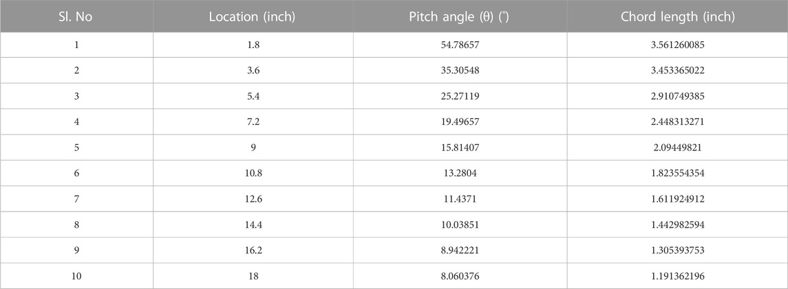
TABLE 1. Estimation of pitch angle chord length of main rotor blade.
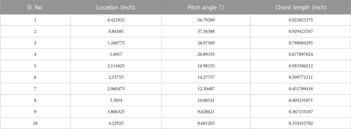
TABLE 2. Estimation of Pitch angle & Chord length of Tail rotor blade.
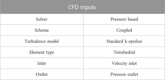
TABLE 3. Important input parameters involved in CFD analysis.
The design flow of RUAV consists of several stages. The planned RUAV will be having a body like helicopter, one main rotor, and a nozzle mechanism for dropping payload. The historical relationships and literature survey gave the necessary data for the RUAV design calculations. With the help of design calculations, the conceptual design model of RUAV has been made using CATIA software. For ensuring the quality of design and for the optimization of the design, the CAD (computer aided drafting) model has been incorporated to ANSYS 17.2 Fluent for CFD analyzes, and the results will be obtained to get an optimized and efficient model of RUAV.
From the historical data, the relationship between payload weight and maximum take-off weight is derived that is graphically represented in Figure 1. The payload weight is assumed as 22.5 kg to carry the cleaner for air pollution at large terminals like railway stations, bus stands, Temples, churches, etc., Based on the defence applications, the UAV’s speed is assumed as 25 m/s and the atmospheric velocity is measured as 3 m/s.
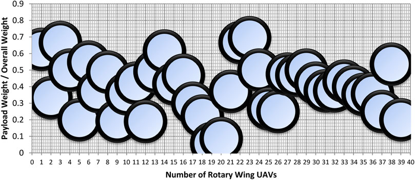
FIGURE 1. Historical relationship derived for proposed rotary wing UAV.
The payload weight is assumed as 22.5 kg to carry the cleaner for air pollution at large terminals like railway stations, bus stands, temples, churches, etc., From Figure 1, the historical relationship between overall weight of RUAV and its payload weight has been framed that is given in Eq. 1 (Mathaiyan et al., 2021; Murugesan et al., 2021; Raja et al., 2021; Senthilkumar et al., 2021; Raja et al., 2022a; Vijayanandh et al., 2022a; Raja et al., 2022b; Raja et al., 2022c; Raja et al., 2022d; Raja M. K. et al., 2022; Wang et al., 2022; Raja et al., 2023).
Based on the defence applications, the UAV’s speed is assumed as 25 m/s and the atmospheric velocity is measured as 3 m/s.
The thrust and power required by the main rotor of RUAV are expressed in Eqs 2, 3. The air enters the stream tube with velocity Vc and then acquires an additional velocity Vi as it passes through the helicopter rotor disk, and finally, it forms the wake with a velocity Vc + Vi. Applying the principles of conservation for mass, momentum, and energy like in the hover we get: The thrust force is equal to,
At vertical climb without inclusion of drag, the thrust force is equal to,
The typical relationship between mechanical power required and its subordinates of drone design parameters is given in Eq. 4 (Mathaiyan et al., 2021; Murugesan et al., 2021; Raja et al., 2021; Senthilkumar et al., 2021; Raja et al., 2022a; Vijayanandh et al., 2022a; Raja et al., 2022b; Raja et al., 2022c; Raja et al., 2022d; Raja M. K. et al., 2022; Wang et al., 2022; Raja et al., 2023).
Eq. 5 is representing the dynamic thrust relationship for drone, wherein the design parameters of propellers are plays major role. To proceed further, the additional unknowns presented are reduced through comparative relationship approach (Mathaiyan et al., 2021; Murugesan et al., 2021; Raja et al., 2021; Senthilkumar et al., 2021; Raja et al., 2022a; Vijayanandh et al., 2022a; Raja et al., 2022b; Raja et al., 2022c; Raja et al., 2022d; Raja M. K. et al., 2022; Wang et al., 2022; Raja et al., 2023).
From the literature survey it was found that propeller hub thicknesses are varies from 48.9 mm to 50 mm, the internal diameter of hub is 32 mm, and external diameter of hub is 50 mm. From the base of pitch description, the pitch relationship is expressed in Eq. 6 (Mathaiyan et al., 2021; Murugesan et al., 2021; Raja et al., 2021; Senthilkumar et al., 2021; Raja et al., 2022a; Vijayanandh et al., 2022a; Raja et al., 2022b; Raja et al., 2022c; Raja et al., 2022d; Raja M. K. et al., 2022; Wang et al., 2022; Raja et al., 2023).
For specific locations on the rotor blade, the pitch angle and chord length are determined using Formulae 7, 8. For sample calculation the 10% of radius, i.e., r = 1.8 inch, has been picked (Mathaiyan et al., 2021; Murugesan et al., 2021; Raja et al., 2021; Senthilkumar et al., 2021; Raja et al., 2022a; Vijayanandh et al., 2022a; Raja et al., 2022b; Raja et al., 2022c; Raja et al., 2022d; Raja M. K. et al., 2022; Wang et al., 2022; Raja et al., 2023).
The chord length is expressed in Eq. 8,
The estimated CL is 0.5617034. Therefore,
As similar as previously shown calculations, the other sectional calculations are determined. The complete design data of main rotor blade is listed in Table 1 (Mathaiyan et al., 2021; Murugesan et al., 2021; Raja et al., 2021; Senthilkumar et al., 2021; Raja et al., 2022a; Vijayanandh et al., 2022a; Raja et al., 2022b; Raja et al., 2022c; Raja et al., 2022d; Raja M. K. et al., 2022; Wang et al., 2022; Raja et al., 2023).
From the historical data and literature survey the relationship between main rotor and tail rotor was obtained, which is expressed in Eq. 9 (Mathaiyan et al., 2021; Murugesan et al., 2021; Raja et al., 2021; Senthilkumar et al., 2021; Raja et al., 2022a; Vijayanandh et al., 2022a; Raja et al., 2022b; Raja et al., 2022c; Raja et al., 2022d; Raja M. K. et al., 2022; Wang et al., 2022; Raja et al., 2023).
The
The
The thrust production relationship of tail rotor is expressed in Eq. 12 and then the pitch relationship is mentioned in Eq. 13 (Mathaiyan et al., 2021; Murugesan et al., 2021; Raja et al., 2021; Senthilkumar et al., 2021; Raja et al., 2022a; Vijayanandh et al., 2022a; Raja et al., 2022b; Raja et al., 2022c; Raja et al., 2022d; Raja M. K. et al., 2022; Wang et al., 2022; Raja et al., 2023).
As similar as main rotor calculation procedure, the tail rotor design parameters are determined. At 10% of radius, r = 0.422925 inch (Mathaiyan et al., 2021; Murugesan et al., 2021; Raja et al., 2021; Senthilkumar et al., 2021; Raja et al., 2022a; Vijayanandh et al., 2022a; Raja et al., 2022b; Raja et al., 2022c; Raja et al., 2022d; Raja M. K. et al., 2022; Wang et al., 2022; Raja et al., 2023).
The chord length of the tail rotor is,
The estimated CL is 0.539538. Therefore,
As similar as previously shown calculations, the other sectional calculations are determined. From the literature survey, the needful other details are found out, which are: propeller hub thickness is 10 mm–11.1 mm, internal diameter of hub is 6.35 mm, and external diameter of hub is 10 mm (Mathaiyan et al., 2021; Murugesan et al., 2021; Raja et al., 2021; Senthilkumar et al., 2021; Raja et al., 2022a; Vijayanandh et al., 2022a; Raja et al., 2022b; Raja et al., 2022c; Raja et al., 2022d; Raja M. K. et al., 2022; Wang et al., 2022; Raja et al., 2023).
Estimation of the distance that is between the main rotor shafts to the tail rotor shaft has been uniquely framed and also expressed in Eq. 14. The other conventional as well as modified relationships relevant with main rotor are expressed in Eqs 15, 16 (Mathaiyan et al., 2021; Murugesan et al., 2021; Raja et al., 2021; Senthilkumar et al., 2021; Raja et al., 2022a; Vijayanandh et al., 2022a; Raja et al., 2022b; Raja et al., 2022c; Raja et al., 2022d; Raja M. K. et al., 2022; Wang et al., 2022; Raja et al., 2023).
The overall length of fuselage of RUAV is uniquely expressed in Eq. 17, in which the conceptualization of RUAV has been played the major role (Mathaiyan et al., 2021; Murugesan et al., 2021; Raja et al., 2021; Senthilkumar et al., 2021; Raja et al., 2022a; Vijayanandh et al., 2022a; Raja et al., 2022b; Raja et al., 2022c; Raja et al., 2022d; Raja M. K. et al., 2022; Wang et al., 2022; Raja et al., 2023).
The nature of this UAV is unmanned one so unwanted space for crew has been removed and thus the shape and dimensions of the fuselage of the RUAV is used form the standard symmetrical aerofoil. The implemented aerofoil is NACA-0024. The comprehensive fineness ratios between design parameters of fuselage of RUAV are derived in Eqs 18, 19, 20 (Mathaiyan et al., 2021; Murugesan et al., 2021; Raja et al., 2021; Senthilkumar et al., 2021; Raja et al., 2022a; Vijayanandh et al., 2022a; Raja et al., 2022b; Raja et al., 2022c; Raja M. K. et al., 2022; Wang et al., 2022; Raja et al., 2023).
At hovering, the thrust force is equal to weight.
For vertical climb, we know that, Lift = Weight + Drag; The relevant aerodynamic forces and their associates are mentioned in Eqs 23, 24, 25. The parasite drag area (
Where, k varying from 9 (for old helicopters) to 2.5 for current low-drag helicopters
The estimation of parasite drag is given in Eq. 24 and lift is mentioned in Eq. 25.
From the equilibrium force equation, the following steps are estimated.
Another force balance equation is given in Eq. 26, wherein drag is very low compared than main rotor so the tail rotor is assumed to be zero (Mathaiyan et al., 2021; Murugesan et al., 2021; Raja et al., 2021; Senthilkumar et al., 2021; Raja et al., 2022a; Vijayanandh et al., 2022a; Raja et al., 2022b; Raja et al., 2022c; Raja et al., 2022d; Raja M. K. et al., 2022; Wang et al., 2022; Raja et al., 2023).
The rotor blades should produce more lift with less drag in order to attain efficient flight. Reynolds number is taken as 1,000,000 for main rotor and 200,000 for tail rotor. Several airfoils are collected and plotted with their respective CD values. The CL required for main rotor blade is 0.561 and for tail rotor blade is 0.539. NACA 2412 is found to be the suitable airfoil for both main and tail rotor blades as it generates the required CL with the least CD among the other airfoils at given conditions. The comparative graphs of airfoils are depicted below (Mathaiyan et al., 2021; Murugesan et al., 2021; Raja et al., 2021; Senthilkumar et al., 2021; Raja et al., 2022a; Vijayanandh et al., 2022a; Raja et al., 2022b; Raja et al., 2022c; Raja et al., 2022d; Raja M. K. et al., 2022; Wang et al., 2022; Raja et al., 2023). The design includes the rotor blades with hub, and the payload mechanism along with the landing gear. From the theoretical calculations, the CAD model is designed using CATIA software. Figure 2 is the drafted representation of RUAV with dimensions.
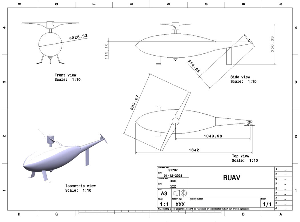
FIGURE 2. A typical representation of design draft of RUAV model.
For the preliminary CFD analysis, the CAD model of the RUAV is imported. The CFD analysis is carried out using ANSYS 17.2 Fluent tool. A cylindrical fluid domain is created as the computational domain. Upstream and downstream of the model 2C (two times of the characteristic length), 6C (six times of the characteristic length) is given respectively.
For the structural analysis of the RUAV’s fuselage, hybrid meshing is done with more than 5,000 elements for half fuselage model and 10,000 elements for full fuselage model. Similarly, the main rotor and full fuselage are also discretized. Through hybrid mesh facility, both uniform and non-uniform meshes are framed with the consideration of design. Figures 3, 4 are depicting the different mesh cases for finite element analysis such as half fuselage, full fuselage, and main rotor and complete RUAV.
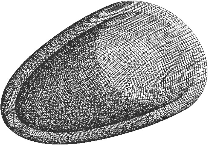
FIGURE 3. Mesh elements of half fuselage model–isometric view.
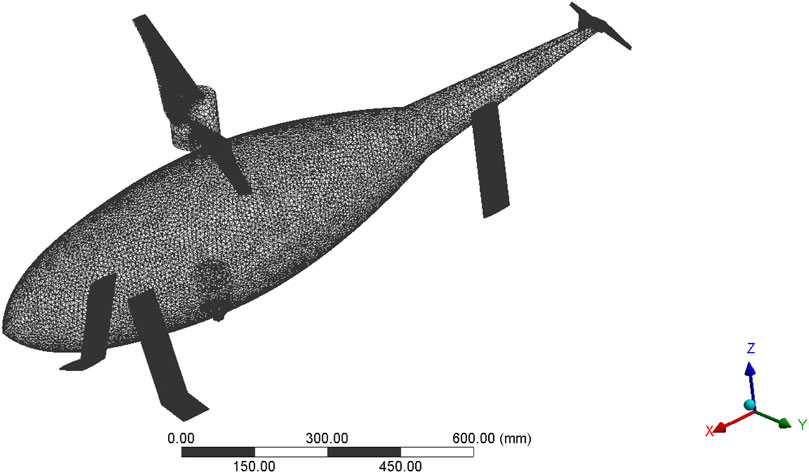
FIGURE 4. A typical isometric representation of discretized structure of RUAV.
For inlet and outlet conditions velocity inlet and pressure outlet are chosen, and it is set as 25 m/s, 0 Pascal, respectively. The pressure load obtained from the CFD analysis has been imported to the ANSYS structural section for the estimation of structural behaviour of the RUAV’s fuselage. The uniformly distributed load has been applied over the fuselage. Finally, the comprehensive imposed boundary conditions on the fuselage models, and entire RUAV are revealed in Figures 5, 6.
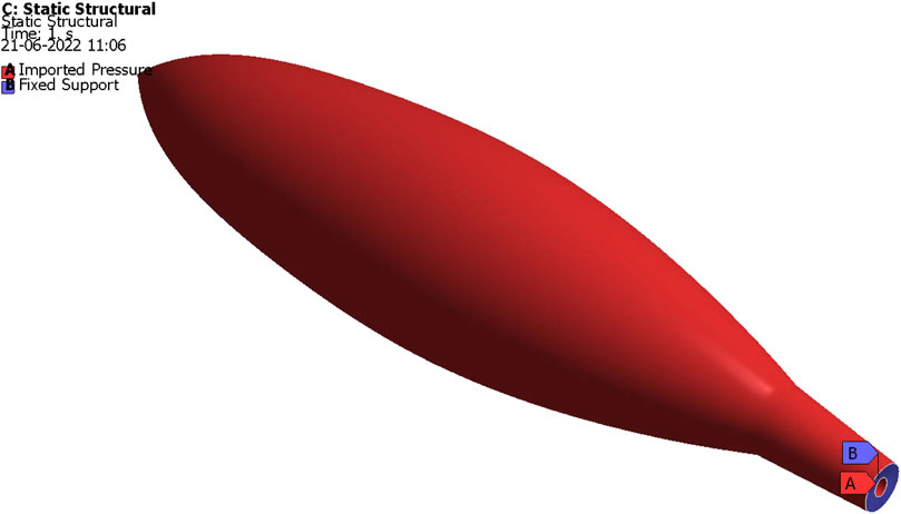
FIGURE 5. Detailed boundary conditions imposed on full fuselage model for FEA.
FIGURE 6. Imposed boundary conditions on RUAV.
CFD analyses have been conducted using ANSYS Fluent tool. The authors have applied pressure based - incompressible flow solver. For getting accurate results, second order upwind spatial discretization has been used. Governing equations are the mathematical formulae which helps to perform the computational simulations. For modeling, they manage the expected behaviour of fluids in the surface provided by the code. Governing equations are the theoretical approximations for describing the fluid flow, structural representations and their components. The stress relationships of orthotropic materials (O.T) are provided in Eqs 27–29 and for isentropic materials in Eqs 30–32.
To test the reliability of the imposed advanced computations procedures through ANSYS Workbench 17.2, the experimental test based validation test on the attained computational outcomes are mandatory. Thus, high-speed jet facility based experimental test results and this work imposed computational procedures based outcomes are compared with each other. The typical high-speed jet facility is revealed in Figure 7.
FIGURE 7. Test setup for high pressure load development.
The experimental tests are conducted at normal atmospheric condition at outside and high-pressurized conditions at inside the jet-path. The typical experimental test setup long with test specimen is revealed in Figure 23.
The given high pressure is 40 bar so the aluminium based test specimen is broken due to high aerodynamic load but the CFRP based test specimen is retained its structural integrity. The imposed test specimens of aluminium alloy and the typical structural failure of aluminium alloy based test specimen is revealed in Figure 8. From the previous experimental results, it was found that the ultimate stress of the woven CFRP is 3,500 MPa and the ultimate stress of the enhanced aluminium alloy is 690 MPa. After successful conduction of experimental tests, the computational tests are computed in ANSYS Workbench 17.2. The design data of experimental test-up and computational test specimen are exactly given in the generation of computational platform of high-speed jet path associated with computational test specimen. The pressure inlet based computational simulation is carried out on the discretized model and so the needful pressure variation on the test specimen has been found. The typical aerodynamic pressure distribution in and over the test specimen is shown in Figure 9. The computed aerodynamic pressure on the model is transferred into computationally developed aluminium alloy and CFRP based composite models thorough system coupling approach in ANSYS Workbench 17.2. Additionally, the FEA based solver is incorporated in this advanced computation and thereafter the ultimate equivalent stresses are obtained on both the models under imposed as well as transferred aerodynamic loading conditions. The structural outcomes of aluminium alloy and CFRP based composite models are projected in Figures 10, 11 respectively.
FIGURE 8. Test specimen after structural failure.
FIGURE 9. Imported pressure on the computational test specimen.
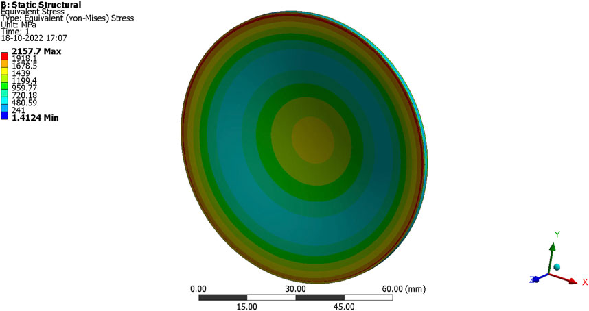
FIGURE 10. Ultimate Equivalent stress of Aluminium Alloy.
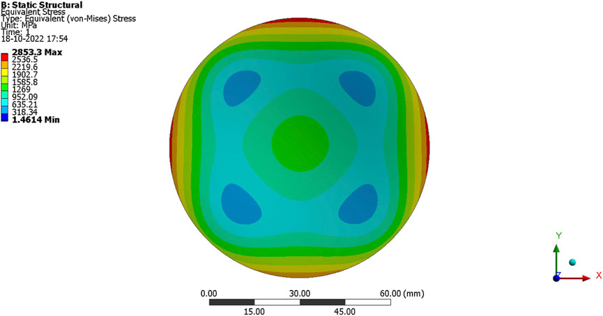
FIGURE 11. Ultimate equivalent stress of CFRP woven based test specimen.
From this computational procedure, it is found that the maximum equivalent stress of the woven CFRP is obtained as 2,853.3 MPa and the maximum equivalent stress of the enhanced aluminium alloy is 2,157.7 MPa. The current authors confirmed that, the imposed advanced FSI technique is developed breaking stress on aluminium alloy and allowable stress for CFRP test specimen. The experimental test setup also provided the broken test specimen of aluminum alloy and unbroken test specimen of CFRP. Thus, these imposed computational procedures can give reliable outcomes so it is finalized to impose on the various components of RUAV.
The second sensitivity test has been computed in this work, in which grid finalization based focal is chosen as primary factor. The deformations based computational outcomes are played the vital contributors on these grid convergence tests. Firstly, the deformation developed by the full fuselage model is investigated for various grid cases. The comprehensive sensitivity outcomes are shown in Figure 12. From Figure 12, 35,000 elements are finalized as suitable discrete counts for the production of reliable outcomes.

FIGURE 12. Total deformation on full fuselage of RUAV with Epoxy-Carbon-Woven-Wet.
Finite Element Analysis (FEA) is the simulation of a physical model using numerical mathematical equations referred to as the Finite Element Method (FEM). Engineers use FEM to reduce the production of physical prototypes and run computational analysis to optimize their designs. FEA is the primary computational analysis technique in industries (Arul Prakash et al., 2022; Vijayanandh et al., 2022b; Vijayanandh et al., 2022c; Madhavi et al., 2022; Malavika et al., 2022; Prabhu et al., 2022; Raj Kumar et al., 2022; Sivaguru et al., 2022).
ANSYS structural software is used here to run and visualize the results of finite element analysis of a RUAV’s fuselage. Initially, the half span of the fuselage has been analyzed with 8 different materials and from that, the best performing 5 materials have been imposed on the entire fuselage. Further to fine-tune the material, hybrid composites have been imposed on the fuselage. The hybrid composites are created by fusing the best performing individual materials. The materials used for analysis are epoxy-E-glass-UD, epoxy-S-glass-UD, epoxy-carbon-UD-prepreg, epoxy-carbon-UD-wet, epoxy-carbon-woven-prepreg, epoxy-carbon-woven-wet, epoxy-e-glass-wet, and aluminum alloy. As per the aforesaid structural boundary conditions and transferred aerodynamic loading conditions, the computational structural investigations are carried on two different fuselage models. Since the aerodynamic conditions are complicated in nature, the two models based structural investigations are computed. Through these two models based detailed outcomes, this paper can give exact material for aerodynamic load resistor in real-time applications. The important structural outcomes of both half, full fuselage, main rotor, and entire RUAV models are systematically shown in Figures 13–30.
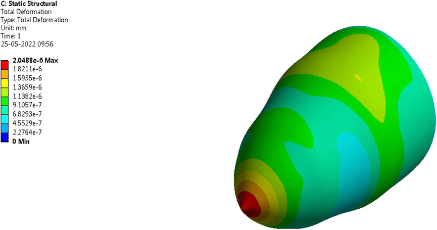
FIGURE 13. Total deformation on half fuselage of RUAV with Epoxy-Carbon-Woven-Wet.
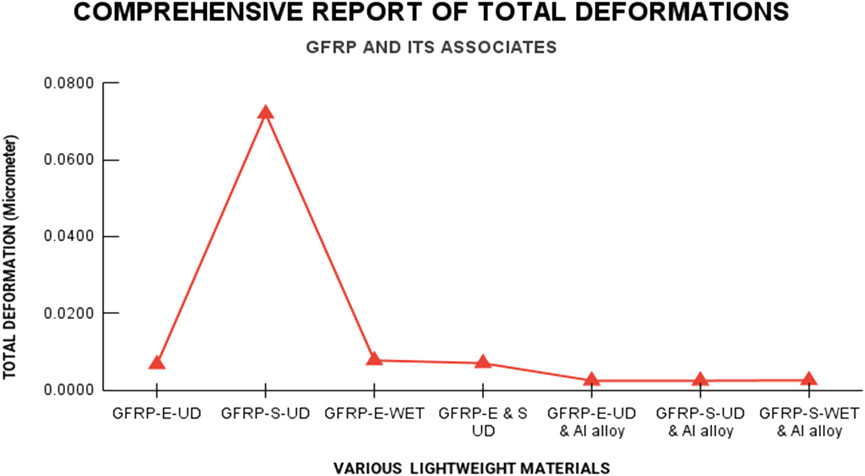
FIGURE 14. Total deformation on half fuselage of RUAV with GFRP and its associate materials.
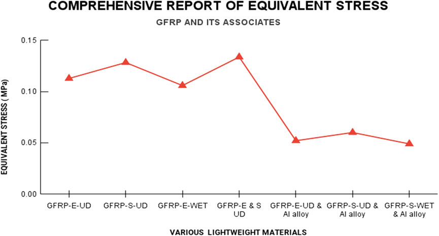
FIGURE 15. Equivalent stress on half fuselage of RUAV with GFRP and its associate materials.
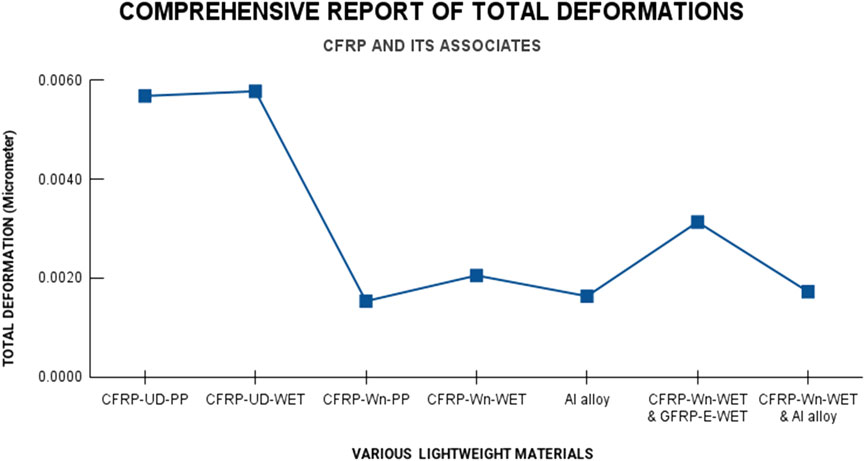
FIGURE 16. Total deformation on half fuselage of RUAV with CFRP and its associate materials.
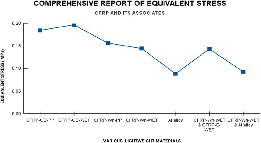
FIGURE 17. Equivalent stress on half fuselage of RUAV with CFRP and its associate materials.
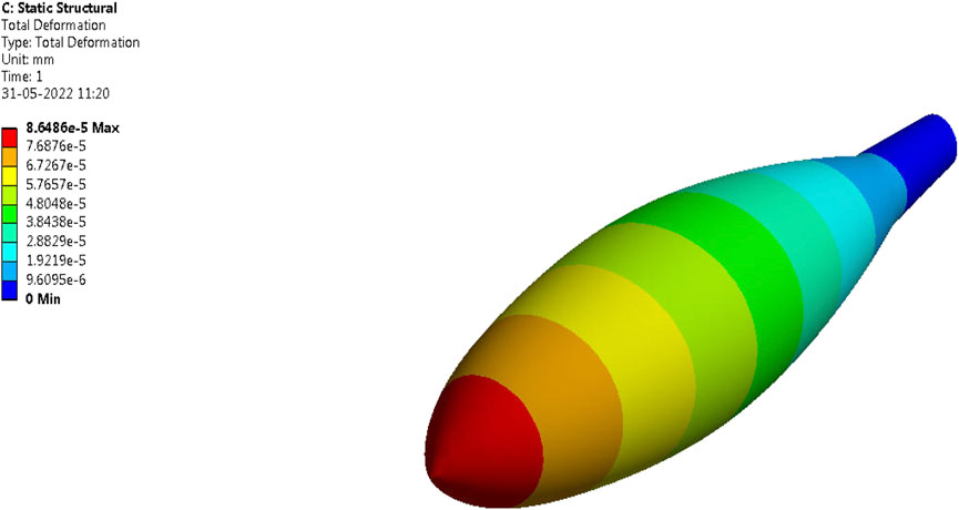
FIGURE 18. Total deformation on full fuselage of RUAV with Epoxy-Carbon-Woven-Wet.
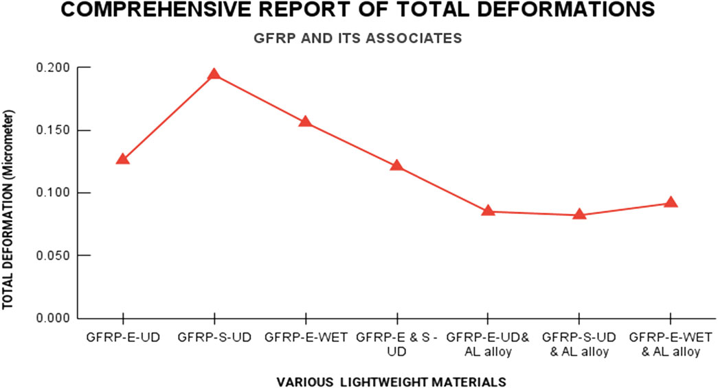
FIGURE 19. Total deformation on full fuselage of RUAV with GFRP and its associate materials.
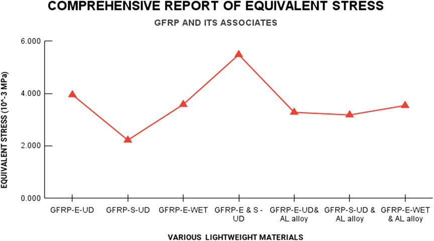
FIGURE 20. Equivalent stress on full fuselage of RUAV with GFRP and its associate materials.
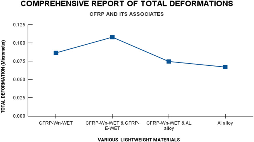
FIGURE 21. Total deformation on full fuselage of RUAV with CFRP and its associate materials.
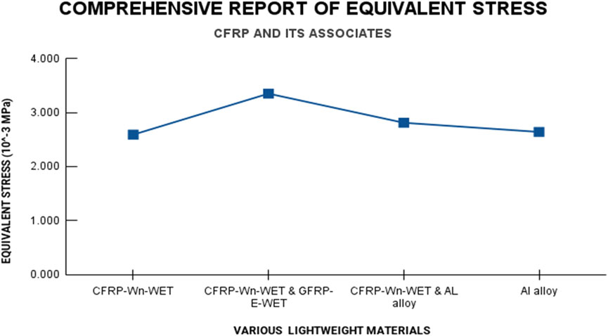
FIGURE 22. Equivalent stress on full fuselage of RUAV with CFRP and its associate materials.
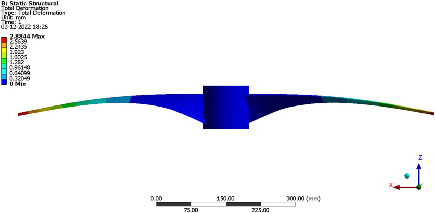
FIGURE 23. CFRP woven wet–Total deformation.
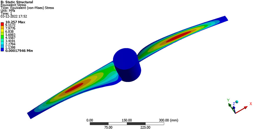
FIGURE 24. Equivalent stress–GFRP-FR-4-Woven.
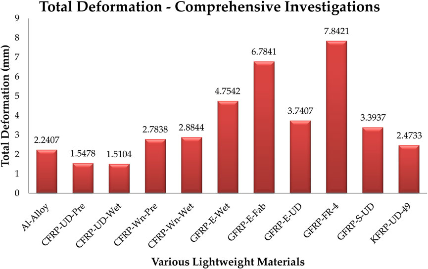
FIGURE 25. Comprehensive report of total deformation of main rotor of RUAV.

FIGURE 26. Comprehensive report of equivalent elastic stress of main rotor of RUAV.
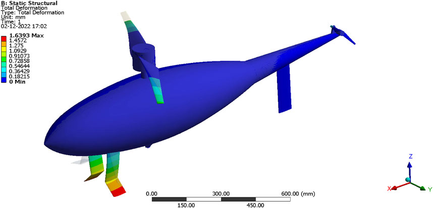
FIGURE 27. CFRP-woven-prepreg–Total deformation.

FIGURE 28. FR-4 based woven composite–equivalent elastic stress.
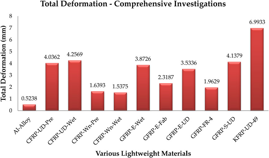
FIGURE 29. Comprehensive report of total deformation of RUAV.
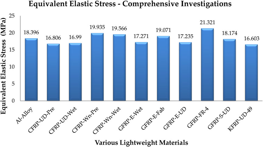
FIGURE 30. Comprehensive report of equivalent elastic stress of RUAV.
Different lightweight conventional and hybrid composite materials have been developed by advanced composite development tool and so imported on RUAV fuselage shapes also analyzed through advanced engineering simulations. Since total deformations are plays major role in FEA approaches, the computational outcomes of deformed structures of various lightweight materials are revealed in Figures 13–17. In addition to the deformations, and equivalent elastic stresses are investigated for both of the traditional and advanced composite aerospace materials. The comprehensive outcomes of various lightweight materials are revealed in Figures 14–17. From the results of half fuselage simulation, three best performing materials have been sorted. They are Epoxy-Carbon-Woven-Wet, Epoxy-Carbon-Woven-Prepreg, and Aluminium alloy (Arul Prakash et al., 2022; Vijayanandh et al., 2022b; Vijayanandh et al., 2022c; Madhavi et al., 2022; Malavika et al., 2022; Prabhu et al., 2022; Raj Kumar et al., 2022; Sivaguru et al., 2022).
The best performing two materials from the full fuselage simulation are Epoxy-Carbon-Woven-Wet and Aluminium alloy. For this second modified computation, the same boundary conditions are imposed and thereafter the primary structural outcomes are computed. In the fine-tuning process with the hybrid composites, Epoxy-Carbon-Woven-Wet with Aluminium alloy produced the favorable output. The displaced structure of full fuselage of RUVA for important lightweight material is revealed in Figure 18. The comprehensive FEA outcomes are revealed in Figures 19–22.
Figures 19–22 describe the graphical representation of different output values of RUAV’s full fuselage analysis. Based on the extensive structural analysis, Epoxy-Carbon-Woven-Wet has been observed as the suitable individual composite material and Epoxy-Carbon-Woven-Wet with Aluminium alloy has been observed as the suitable hybrid composite material.
Fluid Structure Interaction (FSI) investigation has been carried out on the main rotor of RUAV under the given aerodynamic loadings and aforesaid boundary conditions. The major polymer matrix composites and relevant aerospace alloys are used as platform of this computational structural analysis. Figures 23–26 are demonstrate the important structural computational outcomes of RUAV’s main rotor under different lightweight materials.
The complete RUAV has been subjected to a FSI study using the aforementioned aerodynamic loadings and boundary conditions. This computational structural study is based on the main polymer matrix composites and important aerospace alloys. The important computational structural outcomes of complete RUAV under various lightweight materials are revealed in Figures 27–30.
From comprehensive main rotor Figures 25, 26, as well as comprehensive Figures 29, 30, the following observations are obtained: CFRP-UD-Wet is stiffer for main rotor construction; GFRP-E-Fabric is good to provide high lifetime for main rotor construction; CFRP-Woven-Wet is stiffer for entire RUAV construction; KFRP-UD-49 is good to provide high lifetime for main rotor construction.
The design development, aerodynamic, and structural characteristics of the RUAV are the primary focuses of this study endeavor. In addition to the data that were obtained, comprehensive CFD and FEA computations were carried out in order to estimate the performance of the RUAV through advanced Fluid Structure Interaction based computational investigations. According to the findings of the CFD investigations, the maneuverings can be accomplished by elevating the main rotor’s tilt angle in order to cause an increase in the side forces. The multiple reference frame analysis attempted to determine whether or not the force produced by the tail rotor is sufficient to counteract the force generated by the main rotor. The material that would work best for the design of the RUAV’s fuselage was identified through the use of finite element analysis. The Epoxy-Carbon-Woven-Prepreg and aluminium alloy provided the most satisfying results to the loads in the half fuselage analysis. The Epoxy-Carbon-Woven-Wet and Aluminum alloy provided the most satisfying results to the loads in the half fuselage analysis. Thus, Epoxy-Carbon-Woven-Wet with Aluminum Alloy produced the favorable results in the structural aspects in terms of total deformation, equivalent stress, equivalent elastic strain, strain energy, and normal stress among the hybrid composites that were analyzed. Finally, Carbon Fiber based polymer matrix composite is shortlisted as best material for rotary wing UAV under all kind of complicated aerodynamic loading conditions. Finding the best material for the RUAV’s primary rotor is a secondary goal of this forced FSI research. The primary rotor of the RUAV is analyzed because it is the part that is put under the most stress. This was demonstrated by prior test results. Eleven categories of substances were considered during the study. Total deformation, equivalent stress, equivalent elastic strain, and normal stress were all considered extensively during the research. Total deformation and equivalent elastic strain were found to be lowest for the aluminium alloy, and equivalent stress and normal stress were found to be lowest for the Epoxy-S Glass Unidirectional based composites. The following insights can be gleaned by looking at the comprehensive main rotor results: CFRP-Woven-Wet is stiffer for the entire RUAV construction; KFRP-UD-49 is good to provide high lifetime for main rotor construction; CFRP-UD-Wet is stiffer for the construction of the main rotor; GFRP-E-Fabric is good to provide high lifetime for the construction of the main rotor; and CFRP-UD-Wet is stiffer for the construction of the main rotor.
The original contributions presented in the study are included in the article/Supplementary Material, further inquiries can be directed to the corresponding author.
Conceptualization, VR and PS; methodology, VR, RG, and BB; software, VR and RG; validation, VR and HAL-B.; formal analysis, VR and HAL-B; investigation, VR, BB, and RG; resources, VR, PS, and BB; data curation, VR and RG; writing—original draft preparation, VR; writing—review and editing, PS, BB, and VR; visualization, SE, HAL-B, and PR; supervision, PR and SE; project administration, SE and PR; funding acquisition, SE. All authors have read and agreed to the published version of the manuscript.
This work was partially funded by the research center of the Future University in Egypt, 2022.
These computing resources were generously provided by the Aircraft Design and Analyses Laboratory in the Department of Aeronautical Engineering at Kumaraguru College of Technology (KCT) in Coimbatore-641049, Tamil Nadu, India. Therefore, the authors of this piece appreciate the support of the company’s upper management and the industry’s finest.
HAL-B was empolyed by the Iraqi Ministry of Oil, Midland Refineries Company.
The remaining authors declare that the research was conducted in the absence of any commercial or financial relationships that could be construed as a potential conflict of interest.
All claims expressed in this article are solely those of the authors and do not necessarily represent those of their affiliated organizations, or those of the publisher, the editors and the reviewers. Any product that may be evaluated in this article, or claim that may be made by its manufacturer, is not guaranteed or endorsed by the publisher.
Arul Prakash, R., Vijayanandh, R., Naveen Kumar, K., Raj Kumar, G., Muralidharan, R., Dharshini, K. M., et al. (2022). Structural optimization for gravitational vortex hydropower’s rotor through hydro-structural interaction [HSI] analysis. AIP Conf. Proc. 2446, 180022. doi:10.1063/5.0108342
Atmaca, M., Cetin, B., and Yilmaz, E. (2018). CFD analysis of unmanned aerial vehicles (UAV) moving in flocks. Acta Phys. Pol. A 135, 694–696. doi:10.12693/APhysPolA.135.694
Barakos, G. N. (2013). A review of helicopter rotor blade tip shapes. Prog. Aerosp. Sci. 56, 35–74. doi:10.1016/j.paerosci.2012.06.003
Basset, P. M., Tremolet, A., and Lefebvre, T. (2014). Rotary Wing UAV pre-sizing: Past and Present Methodological Approaches at Onera. AerospaceLab 8, 1–12. doi:10.12762/2014.AL08-10
Chen, R., Zhu, X., Zhou, Z., Wang, Z., and Zhang, T. (2018). “Study on the structure design of solar powered UAV,” in IEEE International Conference on Prognostics and Health Management (ICPHM), Seattle, WA, USA, 11-13 June 2018. doi:10.1109/ICPHM.2018.8448618
Kania, W., Stalewski, W., and Zwierzchowska, B. (2007). Design of the modern family of helicopter airfoil. Pr. Inst. LotnictwaNr 4 (191), 51–82.
Krenik, A., and Weiand, P. (2016). Aspects on conceptual and preliminary helicopter design. Braunschweig, Deutschland: Deutscher Luft- und Raumfahrtkongress. Document ID: 420207.
Li, P., and Chen, R. (2010). A mathematical model for helicopter comprehensive analysis. Chin. J. Aeronautics 23 (3), 320–326. doi:10.1016/S1000-9361(09)60222-3,issue
Luka, J. (2016). Development of a rotary-wing preliminary design process. Campbell, Australia: University of New South Wales at the Australian Defence Force Academy. Miles Grey.
Madhavi, N., Harsha Vardhan, K., Thakuri, S., Akhil Goud, B., Dubey, S., Rajendar, U., et al. (2022). A conceptual design of tailless minicopter. AIP Conf. Proc. 2446, 180042. doi:10.1063/5.0109212
Malavika, M., BeninOliver, B., Hariharan, A., Vineethkrishna, U., Raj Kumar, G., Balasubramanian, S., et al. (2022). Experimental and computational structural cum fatigue data investigations on various lightweight materials under tensile load. AIP Conf. Proc. 2446, 180048. doi:10.1063/5.0108365
Mathaiyan, V., Raja, V., Murugesan, R., Kumar Madasamy, S., Gnanasekaran, R. K., Sivalingam, S., et al. (2021). “Conceptual design and numerical analysis of an unmanned amphibious vehicle,” in AIAA Scitech 2021 Forum, 11–15 and 19–21 January 2021. VIRTUAL EVENT. doi:10.2514/6.2021-1285
Mishra, A., Pal, S., Singh Malhi, G., and Singh, P. (2020). Structural analysis of UAV airframe by using FEM techniques. Int. J. Mech. Prod. Eng. Res. Dev. 29 (10), 195–204.
Moëll, D., and Nordin, J. (2008). Division of Machine Design, Department of Management and Engineering. Linköping, Sweden: Linköpings University.
Murugesan, K., Vijayanandh, R., Venkatesan, R., Saravanan, R., Senthilkumar, S., and Darshan Kumar, J. (2021). “Conceptual design of high endurance cum hybrid configuration based personal air vehicles with three-Axis solar tracker system,” in 2021 International Conference on Advancements in Electrical, Electronics, Communication, Computing and Automation (ICAECA), Coimbatore, India, 08-09 October 2021, 1–7. doi:10.1109/ICAECA52838.2021.9675683
Park, Y-B., Nguyen, K-H., Kweon, J. H., Choi, J. H., and Han, J. S. (2011). Structural analysis of a composite target-drone. Int’l J. Aeronautical Space Sci. 12 (1), 84–91. doi:10.5139/IJASS.2011.12.1.84
Prabhu, M., Murugan, K., Kumar Solaiappan, S., Solaiappan, S. K., Raji, A. P., Gnanasekaran, R. K., et al. (2022). “Design and multi-perspective based computational analyses of flying wing UAV for rescue applications at cryogenic environments,” in AIAA AVIATION 2022 Forum, Chicago, IL, June 27-July 1, 2022. doi:10.2514/6.2022-3586
Raj Kumar, G., Vijayanandh, R., Naveen Kumar, K., Arul Prakash, R., Senthil Kumar, M., Sabarish Prabhu, N., et al. (2022). Material and cross sectional shape optimizations on polymer matrix composites through computational structural analysis under crippling load. AIP Conf. Proc. 2446, 150005. doi:10.1063/5.0108356
Raja, M. K., Saravana Mohan, H., Thangavel, S., Raja, V., Gnanasekaran, R. K., and Sivasankaran, A. N. (2022). Design and computational investigations of aerobot for titan using propeller equipped maneuverability system with droppable weather stations. Bangalore, India: SAE International. SAE Technical Paper 2022-26-0014. doi:10.4271/2022-26-0014
Raja, V., Arul Prakash, R., Kumar, A., and de J. Pacheco Diego, A. (2023). Multi-disciplinary engineering design of a high-speed nature-inspired unmanned aquatic vehicle. Ocean. Eng. 270, 113455. doi:10.1016/j.oceaneng.2022.113455
Raja, V., Gnanasekaran, R. K., Rajendran, P., Mohd Ali, A., Rasheed, R., Al-bonsrulah, H. A. Z., et al. (2022). Asymmetrical damage aspects based investigations on the disc brake of long-range UAVs through verified computational coupled approaches. Symmetry 14, 2035. doi:10.3390/sym14102035
Raja, V., Madasamy, S. K., Rajendran, P., Ganesan, S., Murugan, D., Al-bonsrulah, A. Z., et al. (2022). Nature-Inspired design and advanced multi-computational investigations on the mission profile of a highly manoeuvrable unmanned amphibious vehicle for ravage removals in various oceanic environments. J. Mar. Sci. Eng. 10, 1568. doi:10.3390/jmse10111568
Raja, V., Murugesan, R., Rajendran, P., Palaniappan, S., Al-bonsrulah, H. A. Z., Jayaram, D. K., et al. (2022). Multi-domain based computational investigations on advanced unmanned amphibious system for surveillances in international marine borders. Aerospace 9, 652. doi:10.3390/aerospace9110652
Raja, V., Solaiappan, S. K., Kumar, L., Marimuthu, A., Gnanasekaran, R. K., and Choi, Y. (2022). Design and computational analyses of nature inspired unmanned amphibious vehicle for deep sea mining. Minerals 12, 342. doi:10.3390/min12030342
Raja, V., Solaiappan, S. K., Rajendran, P., Madasamy, S. K., and Jung, S. (2021). Conceptual design and multi-disciplinary computational investigations of multirotor unmanned aerial vehicle for environmental applications. Appl. Sci. 11, 8364. doi:10.3390/app11188364
Romeo, G., and Frulla, G. (2002). “Aerodynamic and structural analysis of HAVE solar powered platform,” in AIAA's 1st Technical Conference and Workshop on Unmanned Aerospace Vehicles, Portsmouth, Virginia, May 20–23, 2002. doi:10.2514/6.2002-3504
Saharudin, M. F. (2016). Development of tilt-rotor unmanned aerial vehicle (UAV): Material selection and structural analysis on wing design. IOP Conf. Ser. Mater. Sci. Eng. 152, 012017. doi:10.1088/1757-899X/152/1/012017
Schwinn, D. B., Weiand, P., Schmid, M., and Buchwald, M. (2018). “Structural sizing of a rotorcraft fuselage using an integrated design approach,” in 31st Congress of the International Council of the Aeronautical Sciences (ICAS), Belo Horizonte, MG, Brazil, September 2018.
Senthilkumar, S., Anushree, G., Darshan Kumar, J., Vijayanandh, R., Raffik, R., Kesavan, K., et al. (2021). “Design, dynamics, development and deployment of hexacopter for agricultural applications,” in 2021 International Conference on Advancements in Electrical, Electronics, Communication, Computing and Automation (ICAECA), Coimbatore, India, 08-09 October 2021, 1–6. doi:10.1109/ICAECA52838.2021.9675753
Sivaguru, M., Sudharsan, R., Indira Prasanth, S., Kesavan, K., Kiran, P., Raj Kumar, G., et al. (2022). Structural optimization of advanced carbon fiber reinforced polymers under flexural load through finite element analysis. AIP Conf. Proc. 2446, 030003. doi:10.1063/5.0108159
Slavik, S. (2004). Preliminary determination of propeller aerodynamic characteristics for small aeroplanes. Acta Polytech. a 44 (2). doi:10.14311/558
Stalewski, W., and Zoltak, J. (2012). “Optimisation of the helicopter fuselage with simulation of main and tail rotor influence,” in 28th International Congress Of The Aeronautical Sciences, Brisbane, Australia, 23–28 September, 2012. Available at: http://www.icas.org/ICAS_ARCHIVE/ICAS2012/PAPERS/811.PDF.
Tamer, A., ücekayali, A. Y., and Ortakaya, Y. (2011). “Design and optimization of helicopter rotor for minimum power required,” in 6th Ankara International Aerospace Conference, Ankara TURKEY, 14-16 September 2011 (METU).
Vijayanandh, R., Naveen Kumar, K., Raj Kumar, G., Arul Prakash, R., Senthil Kumar, M., Indira Prasanth, S., et al. (2022). Material optimization of a contra – rotating propeller for a rotary wing unmanned aerial vehicle. AIP Conf. Proc. 2446, 050003. doi:10.1063/5.0108348
Vijayanandh, R., Prakash, R. A., Manivel, R., Kiran, P., Sudharsan, R., Kumar, G. R., et al. (2022). Design and parametric study of counter-rotating propeller of unmanned aerial vehicles for high-payload applications based on CFD-MRF approach. Int. J. Veh. Struct. Syst. 14 (7), 840–848. doi:10.4273/ijvss.14.7.03
Vijayanandh, R., Senthilkumar, S., Rajkumar, R., Kumar, A., Senthil Kumar, M., Darshan Kumar, J., et al. (2022). Conceptual design and computational investigations of fixed wing unmanned aerial vehicle for medium-range applications. Aut. Connected Heavy Veh. Technol. 18, 353–374. doi:10.1016/B978-0-323-90592-3.00020-3
Wang, Y., Kumar, L., Raja, V., Al-bonsrulah, H. A. Z., Kulandaiyappan, N. K., Amirtharaj Tharmendra, A., et al. (2022). Design and innovative integrated engineering approaches based investigation of hybrid renewable energized drone for long endurance applications. Sustainability 14, 16173. doi:10.3390/su142316173
Keywords: computational composites, deformation analysis, RUAV, stresses, structural effects, composite material
Citation: Raja V, AL-bonsrulah HAZ, Gnanasekaran RK, Eldin SM, Rajendran P, Baskaran B and Sakthivel P (2023) Design and advanced computational approaches based comprehensive structural parametric investigations of rotary-wing UAV imposed with conventional and hybrid computational composite materials: A validated investigation. Front. Mater. 10:1096839. doi: 10.3389/fmats.2023.1096839
Received: 12 November 2022; Accepted: 02 January 2023;
Published: 30 January 2023.
Edited by:
Natrayan L., Saveetha University, IndiaReviewed by:
Sathish Kumar Palaniappan, King Mongkut’s University of Technology North Bangkok, ThailandCopyright © 2023 Raja, AL-bonsrulah, Gnanasekaran, Eldin, Rajendran, Baskaran and Sakthivel. This is an open-access article distributed under the terms of the Creative Commons Attribution License (CC BY). The use, distribution or reproduction in other forums is permitted, provided the original author(s) and the copyright owner(s) are credited and that the original publication in this journal is cited, in accordance with accepted academic practice. No use, distribution or reproduction is permitted which does not comply with these terms.
*Correspondence: Sayed M. Eldin, c2F5ZWQuZWxkaW4yMkBmdWUuZWR1LmVn
Disclaimer: All claims expressed in this article are solely those of the authors and do not necessarily represent those of their affiliated organizations, or those of the publisher, the editors and the reviewers. Any product that may be evaluated in this article or claim that may be made by its manufacturer is not guaranteed or endorsed by the publisher.
Research integrity at Frontiers
Learn more about the work of our research integrity team to safeguard the quality of each article we publish.