 Youbin Lai
- Department of Mechanical Engineering, College of Engineering, Shantou University, Shantou, China
To explore the effect of ultrasonic vibration power and frequency on the residual stress of single-channel iron-based alloy plasma cladding, the single-factor ultrasonic vibration plasma cladding test was designed, and ten groups of single-channel iron-based alloy cladding samples under different process parameters were studied. The drilling method was used to measure the residual stress of the substrate at the beginning, middle and tail positions of each sample cladding layer. The residual stress of the substrate was analyzed and the significant characteristics of the effect of ultrasonic vibration power and frequency on the residual stress at different positions were explored using variance analysis. The results show that the residual stress is significantly reduced after applying ultrasonic waves. When the ultrasonic frequency is constant and the ultrasonic power is 240 W, the residual stress of the formed sample is the smallest. Compared with the unapplied ultrasonic assistance, the residual stress in the X direction is reduced by 62.56%, and the residual stress in the Y direction is reduced by 63.23%. When the ultrasonic power is constant and the ultrasonic frequency is 28 kHz, the residual stress of the formed sample is the smallest. Compared with the unapplied ultrasonic assistance, the residual stress in the X direction is reduced by 17.23%, and the residual stress in the Y direction is reduced by 19.79%. The ultrasonic power significantly affects the middle part of the substrate, and the ultrasonic frequency significantly affects each point of the substrate.
1 Introduction
The Fe-Cr-C alloy system possesses exceptional toughness, strength, wear resistance, and integrative characteristics (Deng et al., 2018; Sá de Sousa et al., 2021). It is commonly used in mechanical components to improve surface abrasion because of its superior economic performance (Shchegolev et al., 2018). As an innovative technique for surface coating preparation, plasma cladding technology provides an efficient solution to the preparation of Fe-based coatings (Zhang et al., 2018; Xie et al., 2022). The technique employs a plasma arc as a mobile heat source. The powder and substrate surface layers melt fast and then solidify under the intervention of a high-intensity plasma arc, forming a high-performance metallurgically bonded cladding layer that considerably enhances the surface characteristics of the substrate material (Zhang et al., 2007; Zhou et al., 2019). The local heat input during the cladding process, on the other hand, might generate a non-uniform temperature field distribution. Local thermoplastic deformation and residual strains are unavoidable in the melt pool and surrounding region under fast cooling and heating process conditions (Artaza et al., 2020; Lai et al., 2022). According to research, the efficiency of residual stress management can approach bottleneck limitations when process factors such as welding speed and current are employed optimally. As a result, investigating a novel compounding process, such as ultrasonic vibration technology, will be extremely beneficial to reducing residual stresses in the cladding layer (Gorunov, 2020; Liu et al., 2022).
The implementation of ultrasonic vibration technologies in additive manufacturing processes can considerably improve melt pool flow characteristics (Zhao et al., 2022). The cavitation bubble rupture and the acoustic pressure generated by the acoustic flow effect modify the flow velocity in the melt pool under the impact of ultrasound, substantially enhancing the unequal distribution in the heat and mass transfer process (Mi et al., 2022). This decreases the temperature gradient, enhances grain refinement and equiaxed grain formation, and efficiently minimizes stress in the coating during solidification (Han et al., 2021). Ultrasonic vibrations are being used by a wide range of researchers in metal additive manufacturing methods to regulate the microstructure and mechanical properties of the clad layer (Li et al., 2020; Todaro et al., 2020; 2021; Zhu et al., 2021, 718). It is, however, primarily employed in laser cladding technology and to a lesser extent in plasma cladding technology. The effect of ultrasonic vibration process parameters on residual strains in plasma cladding has received little attention. Although the processing concept of plasma cladding is similar to that of laser cladding, there are discrepancies in the heat source and the working environment, resulting in distinct residual stress development and distribution. As a result, it is critical to investigate the influence of ultrasonic vibration on the residual stresses of substrate. In this research, the plasma cladding process parameters were found using a one-way test using ultrasonic vibration power and frequency as test variables. variance analysis is used to examine the influence of both on residual stresses at the beginning, middle, and end of the substrate, and the variation of residual stresses at each position is compared. It provides a theoretical basis for reducing the residual stress of plasma cladding by applying ultrasonic vibration.
2 Materials and methods
2.1 Materials
Q235 steel was selected as the base material in this test, and the size was 100 mm × 60 mm × 10 mm. The cladding material was iron-based alloy spherical powder with the particle size of 100–270 mesh and hardness of 62–67 HRC. Its chemical composition is shown in Table 1 and the SEM morphology of the powder is shown in Figure 1.

TABLE 1. Chemical composition of iron-based alloy powder (mass fraction, %).
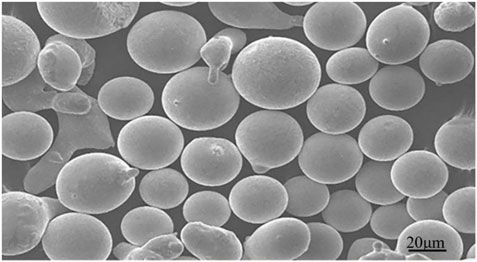
FIGURE 1. SEM morphology of iron-based alloy spherical powder.
2.2 Preparation of test sample
This test was carried out on the self-built ultrasonic vibration assistance plasma cladding system. It was composed of an ultrasonic vibration system and a plasma cladding system. The ultrasonic vibration platform included an ultrasonic power supply, an ultrasonic vibrator, a carrier platform, and a heat shield. The schematic diagram is shown in Figure 2. During operation, the ultrasonic power supply drove the vibrator to generate an ultrasonic wave, and the carrier platform transmitted the ultrasonic wave to the substrate and the cladding layer. Through the continuous action of ultrasonic vibration, the internal structure distribution and residual stress generation of the substrate were affected. The power and frequency of the ultrasonic generator were adjustable. According to the number of vibrators, the maximum power was adjusted to 600 W, and the output frequency was 20 kHz–40 KHz.
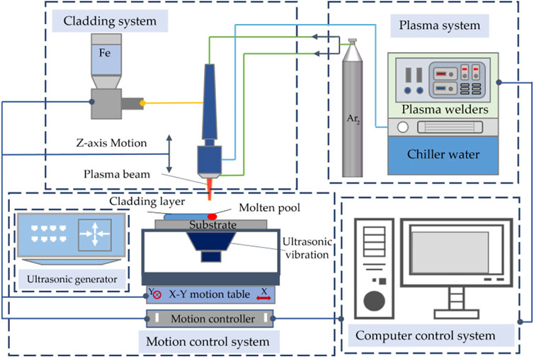
FIGURE 2. Schematic diagram of ultrasonic vibration assistance on the plasma cladding system.
Before the test, the substrate was placed in the heat treatment box and heated to 550°C. After maintaining the temperature for 2 h, it was cooled to room temperature with the heat treatment box to eliminate the residual stress inside the substrate itself. After the heat treatment, the substrate was polished to remove the oxide layer and further cleaned with acetone and alcohol to remove the grease on the surface. The iron-based alloy powder was dried at 120°C to ensure the fluidity and uniformity of the powder during the test (Luo et al., 2019; Li et al., 2022). The effect of ultrasonic vibration power and frequency on the residual stress of the substrate was investigated by a single-factor test. Ten groups of single-channel cladding samples with a cladding length of 60 mm were obtained. The samples with different ultrasonic powers were marked as G1, G2, G3, G4, and G5. The samples with different ultrasonic frequencies were marked as P1, P2, P3, P4, and P5. A group of samples without ultrasonic assistance was marked as No. 0.
2.3 Single-factor test design
The single-factor test was carried out with ultrasonic vibration power and frequency as test factors and residual stress as the test index. The test parameters involved in the test are shown in Table 2.
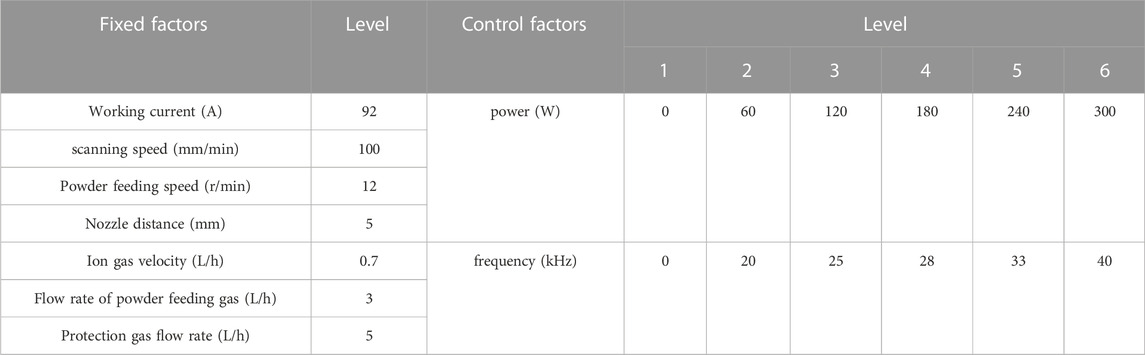
TABLE 2. Test factor level.
2.4 Residual stress measurement
In this test, the residual stress was measured by the drilling method, which was proposed by J. Mathar, 1934 (Mathar) in 1934 and is now widely used in the engineering field. The principle is that a small hole is drilled in the residual stress area. The residual stress around the hole is released, and the residual stress field around the hole changes. The residual stress value at the borehole can be calculated by measuring the strain variation of the local area (Rossini et al., 2012; Kalentics et al., 2017; Schajer and Whitehead, 2018).
In this test, the strain gauge was used to measure the residual stress generated by single-channel samples by drilling method. The schematic diagram of the residual stress test and test samples are shown in Figures 3, 4.
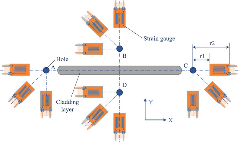
FIGURE 3. Schematic diagram of residual stress test.
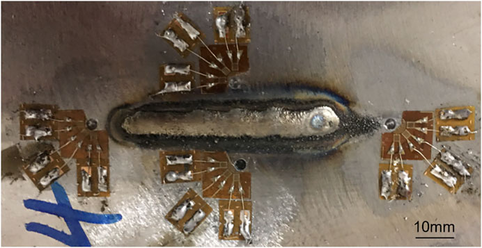
FIGURE 4. Residual stress test samples.
3 Results and analysis
3.1 Calculation of residual stress
The calculation formula of stress release coefficients A and B are as follows (Bo et al., 2014).
In the formula: k is the correction coefficient (1.065); v is the Poisson’s ratio of Q235 steel (0.25);
The calculation formula of the main residual stress
Where,
The component of the residual stress parallel to the X direction of the scanning path is defined as
3.2 Single-factor test result
The drilling method is used to assess the residual stresses in the substrate at the beginning, middle and end of the cladding process. The numerical calculation results of residual stress under different ultrasonic powers are shown in Table 3. The numerical calculation results of residual stress under different ultrasonic frequencies are shown in Table 4.
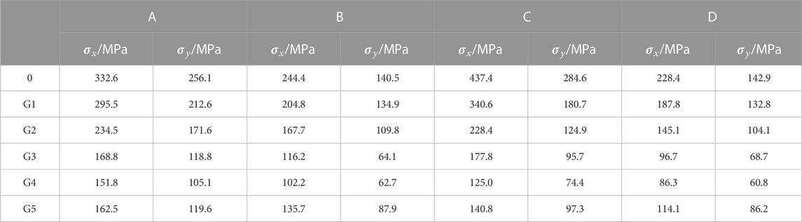
TABLE 3. Residual stress under different ultrasonic powers.
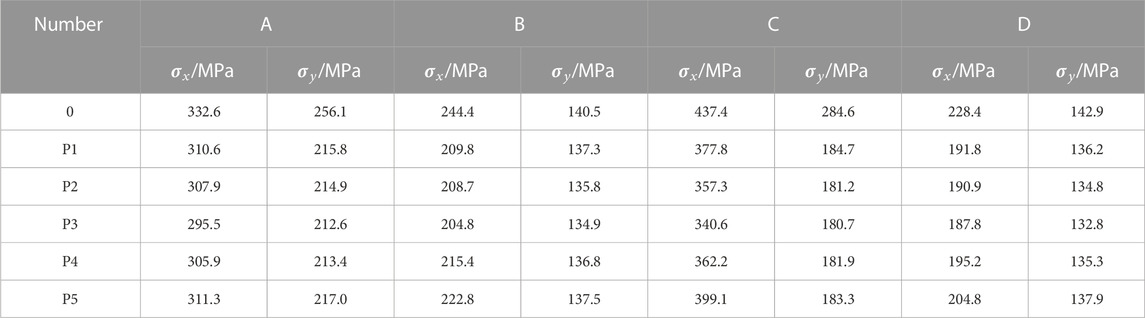
TABLE 4. Residual stress under different ultrasonic frequencies.
3.3 Effect of different ultrasonic parameters on residual stress
3.3.1 Effect of ultrasonic power on residual stress
Figure 5 shows the change of residual stress at each point of the substrate under different ultrasonic powers. From the analysis of the figure, the residual stress in X direction and Y direction at each point of the sample was significantly reduced when the ultrasonic vibration power was within the range of 0–180 W. This was because after the ultrasonic vibration was applied, the cavitation effect, the acoustic flow effect, and the mechanical stirring effect were applied in the molten pool (Zhao et al., 2022). The cavitation effect caused the metal liquid in the molten pool to generate cavitation bubbles, and a large amount of heat was generated after the cavitation bubbles broke to form local shock waves (Zhu et al., 2021, 718). At the same time, the acoustic flow effect and the mechanical stirring effect caused the metal liquid in the molten pool to form a circulation, which accelerated its uniform diffusion. The three effects worked simultaneously and interacted with each other. It could reduce the temperature gradient, so the residual stress was reduced to a certain extent (Liu et al., 2022). When the ultrasonic power was in the range of 180 W–240 W, with the increase of power, the residual stress in X and Y directions decreased slightly. When the ultrasonic power was 240 W, the residual stress of the formed sample was the smallest. Compared with the unapplied ultrasonic assistance, the residual stress in the X direction of the substrate was reduced by 62.56%, and the residual stress in the Y direction of the substrate was reduced by 63.23%. The increase in power reduced the temperature gradient inside the molten pool, so the residual stress was gradually reduced. When the ultrasonic power was in the range of 240 W–300 W, with the increase of power, the residual stress in the X and Y directions increased. This is because while the ultrasonic power is relatively high, the sound pressure inside the molten pool is greater, but the rate of rise in sound pressure decreases as the ultrasonic power increases. When the ultrasonic power reaches a specific threshold and then rises, the sound pressure distribution inside the melt pool is less influenced (Yu, 2020). When the ultrasonic power increased to a certain extent, the thermal effect at the interface would be more obvious, and the hindrance to the timely replenishment of the melt would increase, so the residual stress would increase instead (Yao et al., 2019).
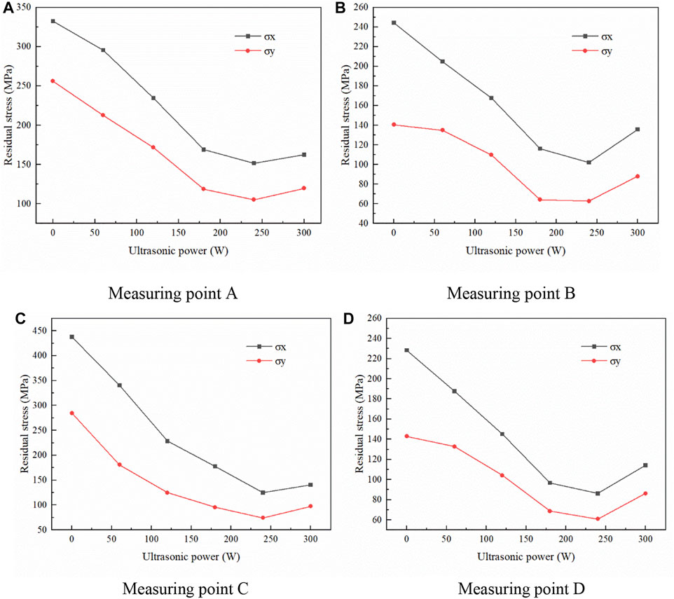
FIGURE 5. Effect of ultrasonic power on residual stress at each point [(A): Measuring point A; (B): Measuring point B; (C): Measuring point C; (D): Measuring point D].
In order to further explore the effect of vibration power on the residual stress at each point, the changes in the residual stress at each point were compared and analyzed in different power ranges. Because the ultrasonic wave was emitted by the vibrator, the power of each vibrator was fixed at 60 W, and the adjustment range would double from 60 W. Therefore, the power range was divided into from 0 W to 60 W as a section, and the effect of ultrasonic waves on the residual stress was analyzed. The power range from 60 W to 240 W was a section, and the result that the residual stress decreased with the increase of power was analyzed. The power range from 240 W to 300 W was a section, and the result that the residual stress increased with the increase of power was analyzed.
Table 5 shows the variation of residual stress at each point with the increase of ultrasonic power from 0 W to 60 W. The decreasing range of point C in the X and Y directions was relatively large because point C was the endpoint of the substrate, the heat accumulation was too large, and the temperature gradient was too large, resulting in greater residual stress. When an ultrasonic wave was applied, the cavitation effect and acoustic flow effect would reduce the temperature gradient in the substrate at the end of the substrate, and the residual stress would be reduced more.
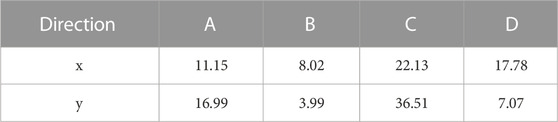
TABLE 5. Reduction of residual stress with ultrasonic power from 0W to 60 W (%).
Table 6 shows the variation of residual stress at each point with the increase of ultrasonic power from 60 W to 240 W. The variation of residual stress at middle point B and point D was close. Because point B and point D were on both sides of the cladding middle, and the accumulation of heat was the same, the variation of residual stress was also the same. After the ultrasonic wave was applied, the temperature field in the middle of the substrate was also distributed on both sides due to the acoustic flow effect.
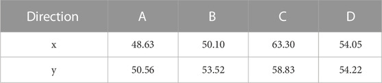
TABLE 6. Reduction of residual stress with ultrasonic power from 60 W to 240 W (%).
Table 7 shows the variation of residual stress at each point with the increase of ultrasonic power from 240 W to 300 W. After the ultrasonic power exceeded 240 W, the residual stress at each point increased in succession, and the changing trend in the X direction of point B and point D changed. This was because when the ultrasonic power increased to a certain extent, the thermal effect at the interface would be more obvious, and the hindrance to the timely replenishment of the melt would increase, so the residual stress would increase relatively. Combined with the characteristics of plasma cladding, the replenishment direction of the melt was perpendicular to the scanning path, namely the X direction. Due to various uncertain factors in the external environment, the hindrance to melt replenishment in the X direction on both sides of the substrate was not the same, so the variation of residual stress in the X direction at points B and point D was also different.
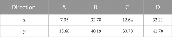
TABLE 7. Increase of residual stress with ultrasonic power from 240 W to 300 W (%).
3.3.2 Effect of ultrasonic frequency on residual stress
Figure 6 shows the variation of residual stress at each point of the substrate at the starting position and the endpoint of cladding process under different ultrasonic frequencies. From the analysis of the figure, the residual stress of the sample in the X direction and the Y direction decreased significantly when the ultrasonic frequency was within 0–20 kHz. This was because after ultrasonic vibration was applied, the cavitation effect, acoustic flow effect and mechanical stirring effect acted in the molten pool and reduced the temperature gradient field, so the residual stress of the substate was reduced to a certain extent (Liu et al., 2022). When the ultrasonic frequency was in the range of 20 kHz–28 kHz, with the increase of frequency, the residual stress in the X and Y directions decreased gradually. When the ultrasonic frequency was 28 kHz, the residual stress of the formed sample was the smallest. Compared with the unapplied ultrasonic vibration, the residual stress in the X direction of the substrate was reduced by 17.23%, and the residual stress in the Y direction of the substate was reduced by 19.79%. It shows that the homogenization effect of the cavitation effect in the molten pool was more obvious with the increase of frequency under the condition of constant power. However, when the frequency exceeded 28 kHz, the residual stress in the X and Y directions gradually increased. This is because the magnitude of the frequency magnitude of the ultrasonic waves has a substantial influence on the acoustic cavitation effect. At higher frequencies, the acoustic field causes the size of the ensuing cavitation bubbles to rise, reducing the energy provided by bubble collapse (Altay et al., 2020). This creates a temperature fluctuation within the melt pool, which may increase residual stresses.
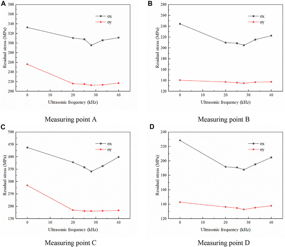
FIGURE 6. Effect of ultrasonic frequency on residual stress at each point [(A): Measuring point A; (B): Measuring point B; (C): Measuring point C; (D): Measuring point D].
In order to further explore the effect of vibration frequency on the residual stress at each point, the changes in residual stress at each point under different frequency sections were compared and analyzed. Due to the characteristics of the ultrasonic vibrators, each vibrator has a frequency of different specifications and cannot be changed. The frequency adjustment range was taken according to the characteristics of the vibrator itself. Therefore, the frequency range was segmented into a section from 0 kHz to 20 kHz, and the effect of the ultrasonic wave on residual stress was analyzed. The section from 20 kHz to 28 kHz was used to analyze the result that the residual stress decreased with the increase of frequency, and the section from 28 kHz to 40 KHz was used to analyze the result that the residual stress increased with the increase of frequency. Table 8 shows the change of residual stress at each point when the frequency increases from 0 kHz to 20 kHz. The change range of residual stress at point C was relatively large because point C was the endpoint, the heat accumulation was too large, and the temperature gradient was too large, resulting in large residual stress. When the ultrasonic wave assistance was applied, the cavitation effect and acoustic flow effect would make the endpoint temperature field uniform, thus reducing the residual stress more.
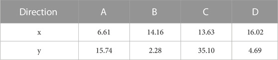
TABLE 8. Reduction of residual stress with ultrasonic frequency from 0 kHz to 20 kHz (%).
Table 9 shows the variation of residual stress at each point when the frequency increases from 20 kHz to 28 kHz. With the increase in frequency, the X-direction residual stress of point A and point C changed greatly. This was because points A and point C were substrate at the starting position and the endpoint of cladding process, the temperature gradient was large, and the residual stress was relatively large. The enormous residual strains at sites A and C are caused by the melt pool’s huge temperature gradient. The significant energy input at the start of the plasma cladding process and the large temperature differential with the original substrate surface as well as the large temperature differential with the original substrate surface, resulting in starting point A. The endpoint C is caused by the significant amount of heat accumulated throughout the cladding process.
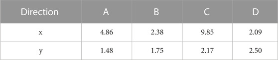
TABLE 9. Reduction of residual stress with ultrasonic frequency from 20 kHz to 28 kHz (%).
Table 10 shows the variation of residual stress at each point when the frequency increases from 28 kHz to 40 KHz. With the increase in frequency, the residual stress of each point increased. On the one hand, the frequency of the ultrasonic waves alters the acoustic pressure inside the melt pool and the duration of the acoustic pressure change (Zhu et al., 2021, 718). When the cavitation bubble vibrating inside the melt pool reaches resonance, it absorbs energy and grows quickly over time, eventually exploding in sub-microsecond time. This will result in temperatures above 5000 K (Suslick, 1995). This is probably why the sample’s elevated residual stresses in the ultrasonic frequency range of 28–40 kHz.
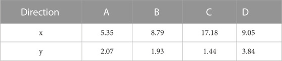
TABLE 10. Increase of residual stress with ultrasonic frequency from 28 kHz to 40 KHz (%).
3.4 Significance of the effect of ultrasonic vibration on residual stress at each point
3.4.1 Significance of the effect of ultrasonic power on residual stress at each point
3.4.1.1 Significance of effect of ultrasonic power on residual stress at each point (point A)
In order to accurately explore the significance of ultrasonic power on the residual stress at the starting point (point A), the test results were analyzed by means of variance analysis. The results are shown in Table 11. The results of variance analysis show that FA1 = 2.30 < F0.05 (1,10) = 4.96, and PA1 > 0.05, indicating that the ultrasonic power had no significant effect on the residual stress at the starting point (point A) within the selected range. This was because, at the beginning of cladding, the substrate temperature was low, and a large temperature difference was formed between the molten pool and the substrate. The temperature difference directly determined the volume change of the molten pool during cooling and solidification. However, the effect of low-power ultrasonic on the temperature field was far less than that of the temperature difference of the substrate itself. Therefore, the ultrasonic power had little effect on the residual stress at the starting point (point A) within the selected range.
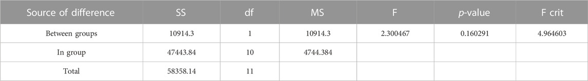
TABLE 11. Variance analysis of ultrasonic power on point A.
3.4.1.2 Effect of ultrasonic power on residual stress in the middle part (point B and point D)
Because points B and point D were in the middle, they were analyzed together. The results are shown in Table 12. The results of variance analysis show that FB1 = 5.52 > F0.05 (1,10) = 4.96, FD1 = 5.72 > F0.05 (1,10) = 4.96 and 0.01 < PB1<PD1<0.05, indicating that the ultrasonic power had a significant effect on the residual stress in the middle part (point B and point D). This was because with the progress of cladding, the substrate temperature had accumulated, and the temperature difference between the molten pool and the substrate had gradually stabilized. After the ultrasonic wave was applied, the acoustic flow effect reduced the temperature gradient of the substrate, thus reducing more residual stress.
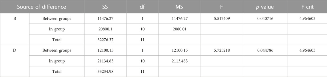
TABLE 12. Variance analysis of ultrasonic power on point B and point D.
3.4.1.3 Effect of ultrasonic power on residual stress at the tail (point C)
For the tail (point C), the test results were analyzed by variance analysis. The results are shown in Table 13. The results of variance analysis show that FC1 = 2.73 < F (1.10) = 4.96, and PC1>0.05, indicating that the ultrasonic power had no significant effect on the residual stress of the tail (point C) within the selected range. This was because, after cladding to the tail, the heat accumulation was the largest, and after cutting off the heat source, the cladding layer and the substrate instantly generated a considerable temperature difference. Similar to the starting point (point A), the change of ultrasonic power had little effect on the temperature field relative to the temperature change of the substrate itself, so the ultrasonic power had little effect on the residual stress of the tail (point C). The residual stress was significantly reduced when the ultrasonic wave was applied but the significance analysis result was not significant. The reason was that the residual stress was indeed reduced after the ultrasonic wave was applied compared with unapplied ultrasonic assistance. However, with the continuous increase of power, the influence of the cavitation effect, acoustic flow effect, and mechanical stirring effect on the residual stress of point C was significantly reduced. Therefore, the analysis showed that the ultrasonic power was not significant for point C within the selected range.
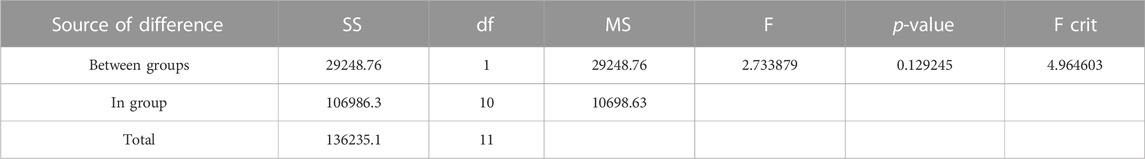
TABLE 13. Variance analysis of ultrasonic power on point B and point D.
3.4.2 Significance of effect of ultrasonic frequency on residual stress at each point
3.4.2.1 The effect of ultrasonic frequency on the residual stress at the starting point (point A)
In order to more accurately explore the significance of ultrasonic frequency on the residual stress at the starting point (point A), the test results were analyzed by variance analysis. The results are shown in Table 14. The results of variance analysis show that FA2 = 109.0 > F0.05 (1,10) = 4.96, and PA2 < 0.01, indicating that the ultrasonic frequency had a significant effect on the residual stress at the starting point (point A). This was because after changing the ultrasonic frequency, the cavitation effect and the acoustic flow effect had a stronger uniform effect on the temperature field of the molten pool and the substrate than the power change, so the temperature difference decreased more. Therefore, the ultrasonic frequency influenced the residual stress at the starting point (point A).
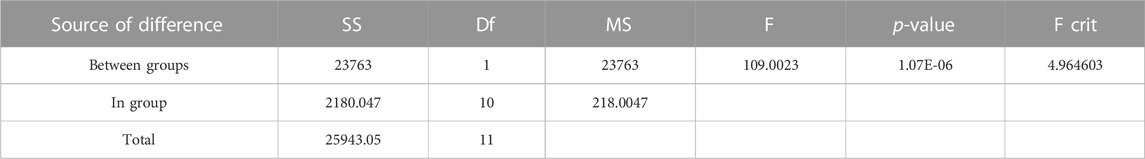
TABLE 14. Variance analysis of ultrasonic frequency effect on point A.
3.4.2.2 The effect of ultrasonic frequency on the residual stress in the middle part (point B and point D)
The results of the variance analysis are shown in Table 15. The results show that FB2 = 181.3631 > F0.05 (1,10) = 4.96, FD2 = 98.74487 > F0.05 (1,10) = 4.96 and PD2 < PB2<0.01, indicating that the ultrasonic frequency had a significant effect on the residual stress in the middle part (point B and point D). This was because the temperature difference between the molten pool and the substrate at point B and point D was basically stable, so after changing the ultrasonic frequency, there was almost no interference from other factors. The frequency change greatly affected the uniformity of the cavitation effect and acoustic flow effect and made the uniformity of the temperature field more remarkable. Therefore, the ultrasonic frequency had a great effect on the residual stress in the middle (point B and point D).
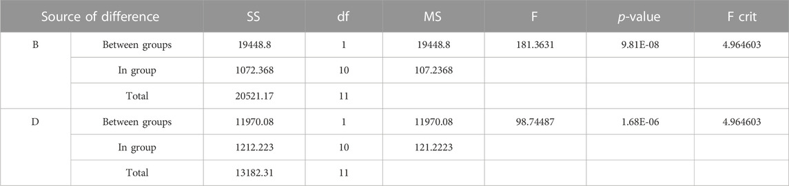
TABLE 15. Variance analysis of ultrasonic frequency effect on point B and point D.
3.4.2.3 The effect of ultrasonic frequency on the residual stress of the tail (point C)
The significance analysis of the residual stress of the tail (point C) was carried out by variance analysis. The results are shown in Table 16. The results of variance analysis show that FC2 = 65.58691 > F (1.10) = 4.96 and PC2<0.01, indicating that the ultrasonic frequency had a significant effect on the residual stress of the tail (point C). The reason was that a strong shock wave was generated in the ultrasonic cavitation process, which would remelt part of the powder, and reduce the temperature difference when the heat source disappeared. Since the frequency had a significant effect on the cavitation effect, the change of frequency greatly affected the change of temperature field, thus having a significant effect on the residual stress of the tail (point C).
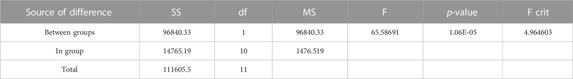
TABLE 16. Variance analysis of ultrasonic frequency effect on point C.
4 Conclusion
Ultrasonic vibration was introduced into the plasma cladding process. The effect of ultrasonic vibration on the residual stress of the substrate was analyzed from two aspects of ultrasonic power and ultrasonic frequency. The following conclusions were got.
1) The introduction of ultrasonic vibration can effectively reduce the residual stress on the surface of the plasma substrate.
2) With the increase of ultrasonic power, the residual stress decreases first and then increases. When the ultrasonic power is 240 W, the residual stress decreases by 62.56% and 63.23% in two directions. When the ultrasonic frequency increases, the residual stress decreases first and then increases. When the ultrasonic frequency is 28 kHz, the residual stress decreases by 17.23% and 19.79% in two directions.
3) In the range of the test parameters, the ultrasonic power only significantly affects the middle position of the cladding substrate, and the ultrasonic frequency significantly affects the start, the middle, and the tail of the cladding substrate.
Data availability statement
The original contributions presented in the study are included in the article/Supplementary Material, further inquiries can be directed to the corresponding author.
Author contributions
Conceptualization, YL; methodology, YL; validation, WY and YZ; formal analysis, WY; investigation, YZ; resources, YL; data curation, YL, WY, and YZ; writing—original draft preparation, WY and YZ; writing—review and editing, YL and WY; visualization, YZ; supervision, YL; project administration, YL; funding acquisition, YL. All authors have read and agreed to the published version of the manuscript.
Funding
This work was supported by the National Natural Science Foundation of China (No. 51605311) and the Natural Science Foundation at Shantou University (No. NTF22002).
Acknowledgments
The authors gratefully acknowledge MS and DW for their help with the experiment and calculations support.
Conflict of interest
The authors declare that the research was conducted in the absence of any commercial or financial relationships that could be construed as a potential conflict of interest.
Publisher’s note
All claims expressed in this article are solely those of the authors and do not necessarily represent those of their affiliated organizations, or those of the publisher, the editors and the reviewers. Any product that may be evaluated in this article, or claim that may be made by its manufacturer, is not guaranteed or endorsed by the publisher.
References
Altay, R., Sadaghiani, A. K., Sevgen, M. I., Şişman, A., and Koşar, A. (2020). Numerical and experimental studies on the effect of surface roughness and ultrasonic frequency on bubble dynamics in acoustic cavitation. Energies 13, 1126. doi:10.3390/en13051126
Artaza, T., Suárez, A., Veiga, F., Braceras, I., Tabernero, I., Larrañaga, O., et al. (2020). Wire arc additive manufacturing Ti6Al4V aeronautical parts using plasma arc welding: Analysis of heat-treatment processes in different atmospheres. J. Mater. Res. Technol. 9, 15454–15466. doi:10.1016/j.jmrt.2020.11.012
Bo, L., Kaihui, H., Dongwei, S., Weicai, Y., Yonggang, C., Mei, L., et al. (2014). Research on measurement of residual stresses of hemispherical lithium hydride by blind-hole method. Fusion Eng. Des. 89, 365–369. doi:10.1016/j.fusengdes.2014.03.016
Deng, X., Zhang, G., Wang, T., Ren, S., Bai, Z., and Cao, Q. (2018). Investigations on microstructure and wear resistance of Fe-Mo alloy coating fabricated by plasma transferred arc cladding. Surf. Coatings Technol. 350, 480–487. doi:10.1016/j.surfcoat.2018.07.040
Gorunov, A. I. (2020). Additive manufacturing of Ti6Al4V parts using ultrasonic assisted direct energy deposition. J. Manuf. Process. 59, 545–556. doi:10.1016/j.jmapro.2020.10.024
Han, X., Li, C., Yang, Y., Gao, X., and Gao, H. (2021). Experimental research on the influence of ultrasonic vibrations on the laser cladding process of a disc laser. Surf. Coatings Technol. 406, 126750. doi:10.1016/j.surfcoat.2020.126750
Kalentics, N., Boillat, E., Peyre, P., Ćirić-Kostić, S., Bogojević, N., and Logé, R. E. (2017). Tailoring residual stress profile of selective laser melted parts by laser shock peening. Addit. Manuf. 16, 90–97. doi:10.1016/j.addma.2017.05.008
Lai, Y., Yue, X., and Yue, W. (2022). A study on the residual stress of the Co-based alloy plasma cladding layer. Materials 15, 5143. doi:10.3390/ma15155143
Li, M., Zhang, Q., Han, B., Song, L., Cui, G., Yang, J., et al. (2020). Microstructure and property of Ni/WC/La2O3 coatings by ultrasonic vibration-assisted laser cladding treatment. Opt. Lasers Eng. 125, 105848. doi:10.1016/j.optlaseng.2019.105848
Li, R., Yuan, W., Yue, H., and Zhu, Y. (2022). Study on microstructure and properties of Fe-based amorphous composite coating by high-speed laser cladding. Opt. Laser Technol. 146, 107574. doi:10.1016/j.optlastec.2021.107574
Liu, Z., Jin, X., Li, J., Hao, Z., and Zhang, J. (2022). Numerical simulation and experimental analysis on the deformation and residual stress in trailing ultrasonic vibration assisted laser welding. Adv. Eng. Softw. 172, 103200. doi:10.1016/j.advengsoft.2022.103200
Luo, K. Y., Xu, X., Zhao, Z., Zhao, S. S., Cheng, Z. G., and Lu, J. Z. (2019). Microstructural evolution and characteristics of bonding zone in multilayer laser cladding of Fe-based coating. J. Mater. Process. Technol. 263, 50–58. doi:10.1016/j.jmatprotec.2018.08.005
Mathar, J. (1934). Determination of initial stresses by measuring the deformations A round drilled holes. IRON STEEL 6.
Mi, H., Chen, T., Deng, Z., Li, S., Liu, J., and Liu, D. (2022). Microstructure and mechanical properties of TiC/TiB composite ceramic coatings in-situ synthesized by ultrasonic vibration-assisted laser cladding. Coatings 12, 99. doi:10.3390/coatings12010099
Rossini, N. S., Dassisti, M., Benyounis, K. Y., and Olabi, A. G. (2012). Methods of measuring residual stresses in components. Mater. Des. 35, 572–588. doi:10.1016/j.matdes.2011.08.022
Sá de Sousa, J. M., Lobato, M. Q., Garcia, D. N., and Machado, P. C. (2021). Abrasion resistance of Fe–Cr–C coating deposited by FCAW welding process. Wear 476, 203688. doi:10.1016/j.wear.2021.203688
Schajer, G. S., and Whitehead, P. S. (2018). Hole-drilling method for measuring residual stresses. Synthesis SEM Lect. Exp. Mech. 1, 1–186. doi:10.2200/S00818ED1V01Y201712SEM001
Shchegolev, A. V., Aulov, V. F., Ishkov, A. V., Ivanayskiy, V. V., and Krivochurov, N. T. (2018). Modification of wear-resistant coatings of Fe-Cr-C system based on the Cr3C2 obtained with help of SHS method. IOP Conf. Ser. Mat. Sci. Eng. 441, 012047. doi:10.1088/1757-899X/441/1/012047
Suslick, K. S. (1995). Applications of ultrasound to materials chemistry. MRS Bull. 20, 29–34. doi:10.1557/S088376940004464X
Todaro, C. J., Easton, M. A., Qiu, D., Brandt, M., StJohn, D. H., and Qian, M. (2021). Grain refinement of stainless steel in ultrasound-assisted additive manufacturing. Addit. Manuf. 37, 101632. doi:10.1016/j.addma.2020.101632
Todaro, C. J., Easton, M. A., Qiu, D., Zhang, D., Bermingham, M. J., Lui, E. W., et al. (2020). Grain structure control during metal 3D printing by high-intensity ultrasound. Nat. Commun. 11, 142. doi:10.1038/s41467-019-13874-z
Xie, F., He, Y., Yuan, Z., and Kang, X. (2022). Microstructure and high-temperature sliding wear performance of Fe-Co-Mo alloy coating fabricated by plasma cladding. Surf. Coatings Technol. 444, 128667. doi:10.1016/j.surfcoat.2022.128667
Yao, Z., Yu, X., Nie, Y., Lu, X., Zhang, Q., and Yao, J. (2019). Effects of three-dimensional vibration on laser cladding of SS316L alloy. J. Laser Appl. 31, 032013. doi:10.2351/1.5098127
Yu, X. (2020). Mechanism of ultrasonic vibration in laser cladding forming and its modelling approach. doi:10.27463/d.cnki.gzgyu.2020.001252
Zhang, D., Yu, R., Chen, K., Yang, X., Liu, Y., and Yin, Y. (2018). Corrosion and corrosion-friction properties of plasma cladding wear-resistant layer on Fe-based alloy. Mat. Res. Express 5, 026525. doi:10.1088/2053-1591/aaae7f
Zhang, L., Sun, D., Yu, H., and Li, H. (2007). Characteristics of Fe-based alloy coating produced by plasma cladding process. Mater. Sci. Eng. A 457, 319–324. doi:10.1016/j.msea.2006.12.047
Zhao, Y., Wu, M., Hou, J., Chen, Y., Zhang, C., Cheng, J., et al. (2022). Microstructure and high temperature properties of laser cladded WTaNbMo refractory high entropy alloy coating assisted with ultrasound vibration. J. Alloys Compd. 920, 165888. doi:10.1016/j.jallcom.2022.165888
Zhou, Y., Zhang, J., Xing, Z., Wang, H., and Lv, Z. (2019). Microstructure and properties of NiCrBSi coating by plasma cladding on gray cast iron. Surf. Coatings Technol. 361, 270–279. doi:10.1016/j.surfcoat.2018.12.055
Keywords: ultrasonic vibration, plasma cladding, iron-based alloy, drilling method, residual stress
Citation: Lai Y, Yue W and Zhang Y (2023) Effect of ultrasonic vibration on residual stress in plasma cladding of iron-based alloy. Front. Mater. 10:1092526. doi: 10.3389/fmats.2023.1092526
Received: 08 November 2022; Accepted: 13 January 2023;
Published: 24 January 2023.
Edited by:
Marta Harničárová, Slovak University of Agriculture, SlovakiaReviewed by:
Pavlo Maruschak, Ternopil Ivan Pului National Technical University, UkraineDonghua Dai, Nanjing University of Aeronautics and Astronautics, China
Copyright © 2023 Lai, Yue and Zhang. This is an open-access article distributed under the terms of the Creative Commons Attribution License (CC BY). The use, distribution or reproduction in other forums is permitted, provided the original author(s) and the copyright owner(s) are credited and that the original publication in this journal is cited, in accordance with accepted academic practice. No use, distribution or reproduction is permitted which does not comply with these terms.
*Correspondence: Youbin Lai, yblai@stu.edu.cn