 Tianzhong Ma1,2
 Shuaihua Ye
94% of researchers rate our articles as excellent or good
Learn more about the work of our research integrity team to safeguard the quality of each article we publish.
Find out more
ORIGINAL RESEARCH article
Front. Mater., 19 September 2022
Sec. Structural Materials
Volume 9 - 2022 | https://doi.org/10.3389/fmats.2022.988455
This article is part of the Research TopicPhysico-Mechanical Properties and Treatment Technology of Hazardous GeomaterialsView all 23 articles
Aiming at the problem of insufficient research on the action mechanism and stability calculation method of the top beam in the pile-anchor support structure, firstly the force and deformation model are established based on the elastic fulcrum method and the deformation coordination principle of the pile-anchor structure at the pile top and the anchor end in this paper. Secondly, the calculation model of the support structure under the synergy of the crown and beam and the simplified calculation method of the internal force, displacement and overall stability of the slope are constructed. Finally, combined with an engineering example, a MATLAB program was compiled for calculation, and the pile-anchor structures with crowned beams and without crowned beams were simulated and calculated by the finite element software PLAXIS 3D and Geo Studio. These three aspects are compared and verified. The results show that the internal force, deformation and minimum safety factor calculated by the method in this paper are basically consistent with the numerical simulation calculation results of the top beam condition; the existence of the top beam effectively enhances the bearing capacity of the pile body, and also restricts the displacement of the pile top development; the synergy of the crown and beam makes the safety factor of the slope increase significantly and improves the safety and stability of the slope. The research in this paper can provide a certain reference value for the theoretical calculation and design of the pile-anchor supported slope considering the top beam in engineering practice.
As one of the main retaining structures in slope treatment, a pile–anchor supporting structure has been widely used and studied because of its strong anti-sliding ability, flexible layout, safety and reliability, less engineering quantity, and so on (Smethurst and Powrie, 2007; Kang et al., 2009; Song and Cui. 2016; Bai et al., 2019; Bai et al. 2021; Bai et al. 2022). The pile–anchor supporting structure is developed based on an ordinary supporting pile, and it uses the elastic foundation beam theory for calculation. Furthermore, the main difference between an ordinary supporting pile and the pile–anchor supporting structure is that the former is similar to the cantilever beam structure whereas the latter can be simplified to a simply supported beam or continuous beam structure. Meanwhile, these structures are statically indeterminate structures that require simplification in the calculation (Cai and UGAI 2011; Huang et al., 2013; Chen et al., 2020).
Many scholars have studied the force and deformation of a pile–anchor supporting structure in a foundation pit and in slope engineering. Some scholars first studied the properties of soil particles and the material composition of supporting structures (Satvati et al., 2020; Zheng et al., 2021). However, the traditional design method of a pile–anchor supporting structure is mainly used to solve the problem of soil strength, and the anchor will deform with the pile in the excavation process. At this time, the existence of an anchor makes the internal force and deformation of the supporting structure more complex (Wang and Zhu. 2014; Di et al., 2018; Ye et al., 2019; Ye and Zhao., 2020). Using the strength parameters of the soil deformation state and the stress mode of a pile–anchor structure, Sun et al. (2019) established a design method for the pile–anchor structure of a deep foundation pit based on deformation. In addition, a method was proposed to unify the limit of plastic development of the soil and the checkpoint of soil deformation in a passive area of a deep foundation pit. Using limit equilibrium theory, Dong et al. (2022) established a stability model of a composite structure that considers the interaction of the anchor prestress and pile. In addition, the actual slip lines passing through the pile body, pile bottom, and soil under the pile, as well as the synergistic effect of the pile body and anchor, were further considered. Finally, the dynamic search algorithm of the model was also provided. Li and Zhang (2020) used a centrifuge test as model verification to study the development law of lateral stress and deformation of the passive pile.
Suo et al. (2016) and Wang et al. (2021) used BOTDA distributed optical fiber sensing technology to test the stress of a pile–anchor supporting system in the process of deep foundation pit excavation and studied the deformation law and internal force distribution characteristics of pile–anchor supporting structures. Furthermore, many scholars (Prat, 2017; Shu and Zhang, 2017; Zhao et al., 2018; Zhang et al., 2020) have used finite software—an indispensable research tool in geotechnical engineering—to explore pile–anchor supporting structures in slope engineering. They mainly studies the deformation and internal force of the supporting structure in the pile–anchor structure supporting slope engineering, the stability of the slope, the types and causes of anchoring failure, the influence of cutting some piles on the load transfer trend of the supporting structure, etc.
Although an existing research analysis has revealed that the research on the synergistic effect of the pile and anchor in pile–anchor supporting structures has been mature, a top beam, which influences the deformation and internal force of the supporting pile, remains in these supporting structures (Zeng and Liu, 1995; Chen et al., 2006). Using the matrix displacement method and considering the pile–anchor as a supporting structure with a synergistic action of the pile, anchor, and soil, Ding and Zhang (2012) explored the influence of the construction process on the deformation of the supporting pile, anchor, and passive soil. Li (2011) used the method of structural mechanics to analyze the whole stress system formed by the connection of the top beam and supporting pile, and the influence of the space effect was considered. This shows that the role of top beams in pile–anchor supporting structures cannot be underestimated. However, the existing research on the theoretical research and calculation analysis of crown-beam cooperative pile–anchor slope supporting structures is relatively rare, and most of the tests consider a top beam a type of safety reserve. In addition, only a few studies have explored the deformation of crown-beam cooperative pile–anchor support in theoretical analysis, which failed to provide the theoretical calculation method of the force and deformation of the three cooperative support and the overall stability of the slope.
In this study, the mechanical models of coordinated deformation and overall stability of supporting structures, such as top beams, supporting piles, and anchors, were established using the elastic fulcrum method. A simplified calculation method was derived by considering the internal force and stability of the supporting slope with a crown-beam cooperative pile–anchor structure and was compared with numerical simulation. In addition, the cooperative action mechanism of the pile, anchor, and top beams in pile–anchor supporting structures was further studied. The important role of top beams in pile–anchor supporting structures was clarified, which can provide some theoretical guidance for designing pile–anchor supports in follow-up engineering practice.
1) Supporting piles, top beams, and retaining plates are all linear elastomers.
2) The anchor rod on the side of the pile is simplified to a linear spring with horizontal stiffness.
3) The interaction between the pile and the surrounding soil is replaced by the soil spring, and the bonding force and friction between the pile and the soil are not considered.
4) The earth pressure varies linearly in the same layer of soil.
On the basis of a single pile’s profile, the slope length is L, the number of piles is n, and the kth pile is inspected. The pile above the slope’s bottom is considered an elastic beam constrained by a top beam and an anchor, and the pile below the slope’s bottom is considered a Winkler elastic foundation beam. Figure 1 shows that the load on the kth pile is ek and the pile top is subject to the binding Tk, the moment Mk of the top beam to the supporting pile, and the anchor tension FTi of multiple rows of anchors to the pile. Under the combined action of the above forces, the supporting pile top produces the horizontal displacement uk and rotation angle θk.
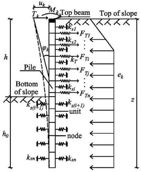
FIGURE 1. Calculation model of a single pile. Where h is the pile’s length above the ground, h0 is the embedded section’s length, z is the supporting pile’s full length, ks is the equivalent stiffness of the soil spring, and kT is the anchor’s axial stiffness.
According to the horizontal displacement uk and rotation angle φk produced at the top of the k supporting pile, the horizontal displacement and rotation angle are caused by the soil pressure on the pile’s side and the influence of the top beam and anchor on the supporting pile force. In addition, some horizontal displacement and rotation angles are produced. According to the deformation coordination of the pile top beam and pile top supporting pile under the action of the anchor, to meet the superposition principle, the relationship can be written as follows:
where the displacement uek and the rotation angle θek are the horizontal displacement and rotation angle generated at the top of the kth pile under the sole action of earth pressure, respectively. δuZTkk and δθZTkk are the displacement and rotation angle of the kth top in the axial direction of the vertical pile when a horizontal unit force acts on the pile top. δuZMkk and δθZMkk are the displacement and rotation angle of the kth pile top in the vertical pile axis when the pile top has a unit external moment. δuP0kFTi and δθP0kFTi are the displacement and rotation angle of the kth pile top in the vertical pile axis when the ith row of the anchor rods of the supporting pile has a horizontal unit force.
At the outer end of the anchor rod of the ith anchor rod, its horizontal displacement is caused by the joint action of the top beam and all anchor rods. According to the coordinated deformation of the anchor rod and the supporting pile under the influence of the top beam, the displacements of the outer end of the anchor rod are as follows:
where the pile body produces a horizontal displacement
In Eq. 1, the calculation ideas of uek, θek, δuZTkk, δθZTkk, δuZMkk, δθZMkk, δuP0kFTi, and δθP0kFTi are as follows:
The vertical supporting pile is divided into a limited number of elements, and one element is divided every 1–3 m. To facilitate calculation, the nodes on the boundary are used to connect the elements in the cross section of the supporting structure, the action point of the anchor, the sudden change in load, and so on. On the basis of the principle of no relative displacement in the coordination of the supporting pile, anchor bar, top beam, and soil, the soil stiffness of the element length is equivalent to soil spring ksi. The anchor force is FTi, and the bolt stiffness is kTi (Figure 1).
The element node load and the element stiffness matrix are generally calculated using the shape function of the compression bar element (Figure 2).
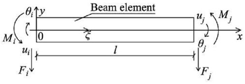
FIGURE 2. Beam element calculation diagram.
The interpolation of the deflection function y(ξ) in the element is shown below.
In the formula:
The main loads acting on the supporting pile are the force of the top beam on the supporting pile, the pulling force of the anchor on the supporting pile, and the earth pressure behind the supporting pile, in which the acting force of the top beam on the supporting pile and the pulling force of the anchor on the supporting pile belong to the nodal load. The earth pressure behind the pile belongs to the non-nodal load. According to the calculation rules of the matrix finite element method, the non-nodal load of the earth pressure behind the pile should be transformed into the equivalent nodal load. Therefore, the load concentration degree of the earth pressure behind the pile is assumed to be p(x), and the equivalent nodal load of the load concentration p(x) in the local coordinate system of element node i and node j is as follows:
where b0 is the beam element width, p(ξ) is the load concentration, l is the element length, Fi is the horizontal load of node i, and Mi is the moment of node i.
When the earth pressure varies linearly in the same soil layer, there are
By integrating Eq. 4 into Eq. 3, the equivalent joint load caused by earth pressure is as follows:
From the analysis of the supporting pile, the element stiffness matrix comprises three parts: the first is the stiffness
The element stiffness
where E is the elastic modulus of the pile, I is the moment of inertia of the pile section, and l is the element length.
According to the beam model of the elastic foundation, the following results can be obtained:
where p(z) is the pressure strength of any point on the pile, w(z) is the horizontal displacement of the pile, m is the horizontal elastic coefficient of the foundation, and z is the pile length.
Eq. 8 can be substituted into Eq. 3 to obtain:
Through integration, the equivalent stiffness esk produced by the soil of the element can be obtained as follows:
where M is the horizontal elastic coefficient of the foundation, l is the element length, and b0 is the width of the beam element.
The stiffness
where E is the elastic modulus of the bolt, Ais the cross-sectional area of the bolt, and li is the bolt length.
The overall stiffness matrix of the structure is obtained by transforming several element stiffness matrixes, and the following formula can be obtained according to the matrix displacement method:
where
From Eq. 12, it can be obtained that the horizontal displacement uek and rotation angle θek of the kth pile top are produced by the supporting pile under the action of earth pressure alone, and when the horizontal unit force and unit external moment act separately on the kth pile top, the vertical pile axis displacements δuZTkk and δθZTkk and rotation angles δuZMkk and δθZMkk occur at the pile top. Using the method of structural mechanics, the flexibility coefficients δuP0kFTi and δθP0kFTi at the pile top can be obtained when the row anchor i has a horizontal unit force.
The top beam can be considered a linear elastic body. On the basis of the analysis of the top beam of the supporting pile, the two ends of the top beam are assumed to be fixed-end constraints (Figure 3), where the length of the top beam is L, the n supporting piles connected to the horizontal force of the top beam have T1, T2, T3,…, Tn, and the bending moments produced by the top beam are M1, M2, M3,…, Mn. Considering the kth pile top on the top beam for analysis, according to the superposition principle, the displacement uk and rotation angle φk of the kth pile on the top beam can be obtained.where δuLFkm is the displacement of the top beam at the kth point when the unit horizontal force at the mth point acts alone and δθLMkm is the rotation angle of the top beam at the kth point when the unit bending moment at the mth point acts alone.
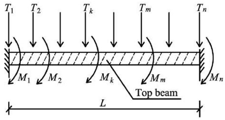
FIGURE 3. Calculation model of the top beam.
Figure 4 shows that when the unit force is applied to a top beam with fixed-end constraints at both ends, the parameter δuLFkm beam can be derived from the knowledge of structural mechanics.where am, bm, xk, and L have their usual meanings, as in Figure 4, E is the elastic modulus of the top beam, and I is the section moment of inertia of the top beam.
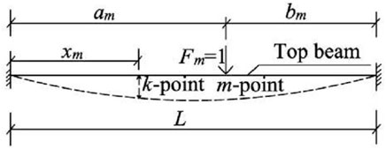
FIGURE 4. Schematic diagram of the calculation of the top beam linear displacement
According to the principle of material mechanics, the equation for the parameter δθLMkm can be derived. As shown in Figure 5, the calculation formula of the δθLMkm equation is shown in Eq. 15. where G is the shear modulus of the top beam, It is the polar moment of inertia of the top beam, L is the length of the top beam, a is the calculation factor of the top beam’s polar moment of inertia, and b is the short side of the section of the top beam rectangle.
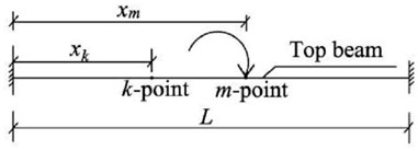
FIGURE 5. Schematic diagram of the calculation of the top beam angular displacement δθLMkmunder a unit force
The horizontal displacement at the anchor end of the i-row anchor under the influence of the top beam is consistent with the deformation of the anchor rod and supporting pile.
where the horizontal displacement of the pile is uei under the action of earth pressure alone. The displacements of the horizontal unit force and the unit moment acting on the kth pile top are, respectively, the displacements of the horizontal unit force and the unit moment acting on the anchor end of the i-row of the pile, the δuPiFTj pile is the displacement of the jth row anchor unit axial force acting on the i-row anchor end of the pile, and the δuPiFTi anchor is the displacement of the ith row anchor unit axial force acting on the anchor end of the supporting pile.
Assuming that the pile bottom is the fixed end, the height of the anchor action point to the supporting pile bottom is li, and the component of the anchor tension in the horizontal direction is FTi, the flexibility coefficients of δuPiTk, δuPiMk, δuPiFTj, and δuPiFTi can be obtained according to the method of structural mechanics. For example, Figure 6 shows the calculation of the δuPiFTj flexibility coefficient.where E is the elastic modulus of the supporting pile, I is the moment of inertia of the supporting pile section, and li, lj are the heights from the point of action of the ith and jth rows of the anchor rods to the bottom of the supporting pile.

FIGURE 6. Schematic diagram of flexibility coefficient δuPiFTjcalculation.
Simultaneously, Eqs 1, 16 can be used to solve 3n unknown quantities, namely, Tk, Mk, and FTi (i ≠ j).
According to the coordinated deformation of the pile-anchor structure at the top of the pile and the end of the anchor:
It can be simplified to a system of linear equations in three variables:
Among them:
To solve Eq. 19, it can be got 3n unknowns, namely, Tk, Mk, and FTi (k = i = 1, 2,…, n).
Taking the kth supporting pile as the research object, the loads acting on the supporting pile include the force Tk and moment Mk of method of the top beam on the supporting pile, the earth pressure ek, and the anchor tension FTi. The finite elementthe beam system on an elastic foundation is selected to solve the internal force and deformation of the kth root supporting pile. The structural equilibrium equation is as follows:
where
1) The form of the slip surface is a circular arc when the whole support system is unstable.
2) The sliding soil zone in the arc is divided into several vertical soil strips, the interaction between the soil strips is ignored, and the arc at the lower end of the soil strip is approximately replaced by a straight line.
3) The shear strength on the slip surface is determined by the Mohr–Coulomb failure criterion.
4) For the pile–anchor supporting system, when the slip surface passes through the anchor and the supporting pile, the supporting structure will provide tensile moment and anti-sliding moment.
5) Search all arc surfaces that may pass through the bottom of the pile and below, and the most dangerous slip surface is the arc surface with the minimum safety factor.
On the basis of the Swedish slice method, without considering the interaction between the two sides of the soil strip, the sliding part of the slope is divided into several soil strips, and the width of the strip bi is 0.5 m. Taking the point of the top surface of the top beam (corresponding to the pile center) as the origin, the Cartesian coordinate system is established, and the arc center is determined according to the tangent line perpendicular to the port of the slip plane. Then, the value of the overall stability safety factor of the slope is the ratio of the anti-sliding moment to the sliding moment on the potential sliding arc. Figure 7 shows the calculation diagram.
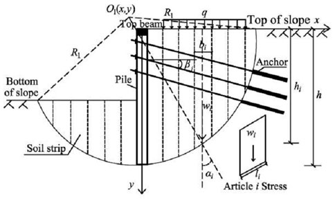
FIGURE 7. Stability calculation diagram.
In Figure 7, O1 is the center of the arc surface, R1 is the arc radius, qi is the additional stress, bi is the i band width, hi is the i band height, wi is the soil weight of the i band, li is the i band bottom length, βi is the inclination of the j layer anchor, ai is the angle between the tangent point of the strip and the arc to the center edge line and the vertical line, and h is the length of the supporting pile.
1) Determination of the internal force of the top beam and anchor
The internal forces of the top beam and anchor can be solved using Eqs 1, 16 of the matrix stiffness equation mentioned above.
2) Calculation of the antislide moment of the supporting pile
where Mp is the anti-slide moment produced by the middle pile per meter, R is the arc radius, ai is the angle between the tangent point of the strip and the arc to the center of the circle and the vertical line, Mc is the bending moment of each pile, hi is the depth from the arc surface to the slope, γ is the weight of soil within the range of hi, kp and ka are the passive and active earth pressure coefficients of soil, respectively, d is the pile diameter, and
The main difference in stability between the slope supported by the top beam combined with the pile and anchor and the ordinary slope is that when the slip surface passes through the anchor and supporting pile, supporting structures such as the top beam, supporting pile, and anchor will provide tensile moment and anti-sliding moment.
The anti-sliding moments Mri, Msi, and MS produced by the bolt and the anti-sliding moment MB produced by the top beam on the sliding arc slope of the ith strip are expressed, respectively, as follows:
The overall stability safety factor of the slope support system is as follows:
where
Consider, for example, the slope support project of a crown-beam synergistic pile–anchor structure in Gansu Province, China. A slope with a length of nearly 120 m needs to be supported on the southeast side of the site. The diameter of the supporting pile is 1,500 mm, the distance between piles is 2,000 mm, the length is 26.4 m, the embedded depth is 13.2 m, and the concrete strength grade of the pile body is C40. The anchor adopts an HRB400 Φ 32 mm steel bar as the main reinforcement, which is located at 2 and 4 m below the pile top. The lengths are 16.5 and 15 m, respectively. The inclination angle is 15°, the anchor diameter is 150 mm, the horizontal spacing of the anchor is 2 m, and the designed pulling force is 110 kN. The section size of the top beam is width × height = 1.5 m × 0.8 m, and the strength grade is C40. Figure 8 shows the support scheme.
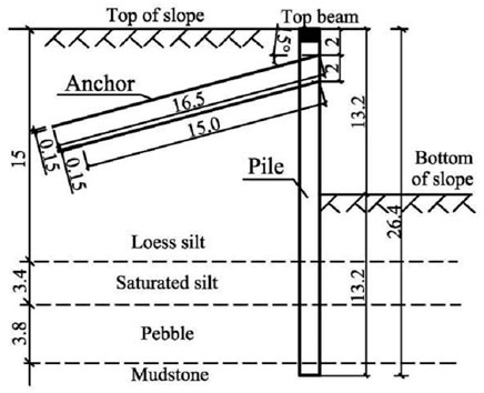
FIGURE 8. Cross section of the supporting structure.
The three-dimensional numerical model of the slope is established using PLAXIS 3D finite element software, and the internal force and displacement of the slope supported by the top beam combined with the pile–anchor structure are calculated. The two sides of the slope are at an angle of 120°, and the lengths of the two sides are 34 and 54 m, respectively. The boundary condition of the model is set according to the actual state of the slope. The upper boundary is free, the surrounding boundary is normally fixed, and the bottom boundary is completely fixed. The distance between the supporting pile and the outer boundary of the slope should be three times or more the height of the slope, and the vertical boundary should be two times or more the height of the slope to avoid the boundary adverse effect on the slope and supporting structure. Usually, the bottom should be taken into hard rock. The dimension of the finite element model is x × y × z = 80 m × 105 m × 40 m. Figure 9 shows the model diagram.
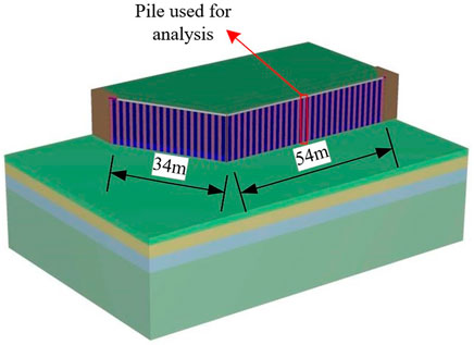
FIGURE 9. Finite element model diagram.
The slope support model of the pile–anchor structure with and without a top beam is established, and Table 1 shows the soil parameters. The soil material simulation uses the soil hardening model (referred to as the HS model). In conventional geotechnical engineering numerical analysis, the soil deformation results obtained using the HS model are most consistent with engineering practice and are significantly better than those of other soil constitutive models. In the numerical simulation, the mesh sparse density is set to “fine,” which is divided into 2,30,447 elements and 3,20,183 nodes, and the relative element size is 0.7 m.
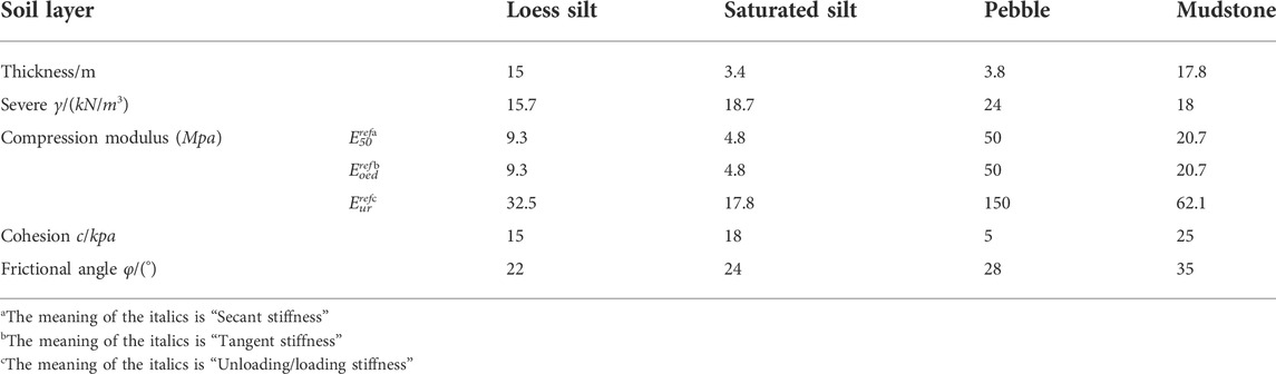
TABLE 1. Soil parameter table.
The material model of the slope supporting structure is linearly elastic, the pile and full-length anchor are simulated by an embedded beam element (embedded pile), the top beam structure is simulated by a beam element, and the concrete baffle is simulated by a plate element. The interface element is established to simulate the interaction between the pile and soil, and the interface is selected as “partially rough.” Table 2 shows the structural design parameters. When the numerical simulation divides the grid, the grid sparse density is set to “fine.” Concurrently, the grid within a certain range of the supporting structure is encrypted, and a fine and accurate grid is generated for the parts where large concentrations or large deformations may occur. A total of 77,196 elements and 1,17,771 nodes are divided.
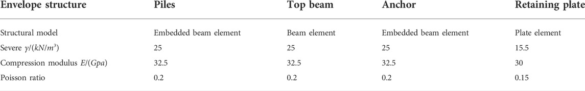
TABLE 2. Structural design parameter table.
The analysis model is established in the SLOPE/W module of GeoStudio. The Morgenstern–Price method is used for slope stability analysis, and the semisine function is selected as the conditional force function. The constitutive relation of soil adopts the Mohr–Coulomb ideal elastic–plastic model, and the parameters of soil and the supporting structure are inputted according to the parameters in Tables 1 and 2. The supporting pile and fully bonded anchor are added by strengthening the load, and the internal force of the top beam is added to the pile top according to the point load. Figure 10 shows that the size of the GeoStudio finite element model is x × y = 60 m × 40 m.
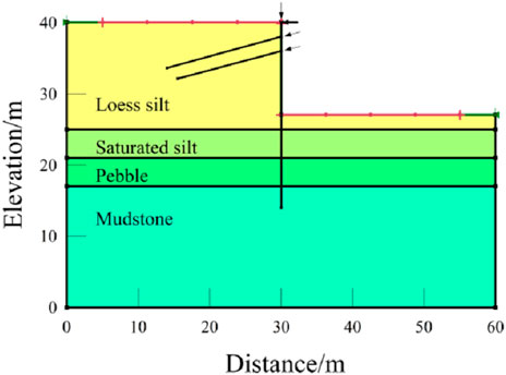
FIGURE 10. Finite element model.
The specific parameters of the project are substituted into the program compiled by MATLAB; the shear force, bending moment, displacement, and minimum safety factor of the slope are calculated; and the results are compared with the simulation results of PLAXIS 3D and GeoStudio software.
From the shear curve of the pile in Figure 11, the calculation results of this method are consistent with the overall stress of the top beam, which verifies the rationality of this method. Under the constraint of the top beam, the shear force at the pile top is similar, but under the condition of no top beam, the shear force at the pile top is −9.78 kN. At the maximum positive shear force of the pile, the maximum shear force calculated by this method and that under the condition of the top beam are 346.81 and 320.4 kN, respectively, which differ from the maximum shear force of the nontop beam. The comparison of the shear force between the pile top and the maximum positive shear force of the pile shows that the top beam can prevent the pile from developing to an empty surface.
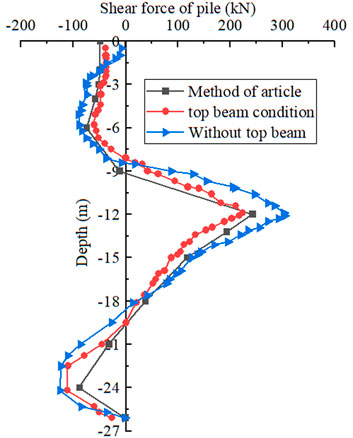
FIGURE 11. Pile shear force comparison chart.
From the comparison diagram of the bending moment of the pile body in Figure 12, the bending moment value obtained by this method is similar to that of the bending moment curve with and without the top beam. However, at the position of the pile top, the bending moment of the nontop beam starts to change from zero, whereas the bending moment at the pile top is −92.21 kN m calculated by this method, and it is −73.92 kN m under the condition of the top beam, indicating that the existence of the top beam can effectively enhance the stress state of the pile top. The maximum positive and negative moment values appear near the buried depth of −9 and −18 m, and the comparison of the working conditions with and without the top beam shows that the existence of the top beam effectively reduces the bending moment of the pile.
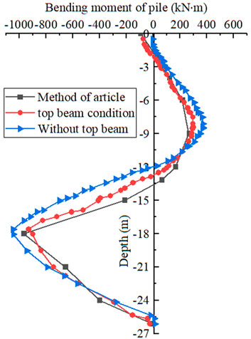
FIGURE 12. Pile body bending moment comparison chart.
From the variation curve of pile displacement in Figure 13, the method presented in this study is similar to the variation law of pile displacement under the conditions of crown and nontop beams. The calculation result of this method is smaller than that of the top beam as a whole, but the existence of the top beam induces a large difference between the crown and nontop beams at the pile top, and the maximum reaches 5.87 mm, which shows that the top beam can connect both sides of the pile to make the top beam and pile deformation, thus reducing the displacement of the pile top and improving the overall stability of the supporting structure.
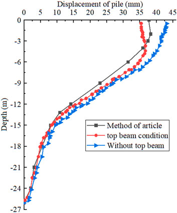
FIGURE 13. Pile displacement comparison chart.
On the basis of the calculation and analysis of the above engineering examples, using the overall stability calculation method in this study, the minimum safety factors of the pile–anchor structure supporting slope with and without a top beam are 1.432 and 1.356, respectively, whereas the minimum safety factors of overall stability with and without a top beam cooperative support obtained by GeoStudio simulation are 1.413 and 1.340, respectively. By comparison, it is found that the calculation result of this method is similar to that obtained by numerical simulation, and the overall safety factors of the slope supported by a top beam and a pile–anchor structure are increased by 5.60% and 5.44%, respectively. Hence, the existence of the top beam significantly improves the overall stability; that is, the safety of the slope is significantly improved.
In this study, a simplified calculation method for solving the internal force and displacement of supporting structures and the overall stability of the slope was proposed by establishing the calculation model of stress deformation and the overall stability of the slope supported by a top beam combined with a pile and an anchor. By taking a slope project of a crown-beam cooperative pile–anchor support as an example, this method was compared with the numerical simulation with and without a crown-beam cooperative support, and the following conclusion are obtained.
(1) According to the deformation coordination principle of the pile–anchor structure at the pile top and anchor end, the integral matrix equation was established by dividing the supporting pile into finite elements, and the calculation expressions of shear force, bending moment, and pile displacement of the supporting pile were obtained.
(2) On the basis of the Swedish slice method, an overall stability analysis of the slope supported by a top beam and pile–anchor was conducted, and the calculation method of the minimum safety factor of the overall stability of the slope was obtained.
(3) The internal force and displacement values calculated by this method were compared with the internal force distribution and deformation values obtained by PLAXIS 3D numerical simulation, and the law was similar. In addition, the slope overall stability coefficient calculated by this method was compared with that obtained by GeoStudio numerical analysis, and their values were close, thereby confirming the rationality of the proposed method.
(4) The numerical simulation results of crown and nontop beams showed that the existence of a top beam can effectively improve the anti-deformation ability of pile, which can more effectively control slope deformation and can increase its overall stability coefficient. As a result, the anti-sliding ability and safety stability of the slope are improved.
The original contributions presented in the study are included in the article/supplementary material, further inquiries can be directed to the corresponding author.
TM and SY completed the drafting of the original paper, and YZ made important revisions to the paper. All authors participated in the theoretical research derivation and numerical simulation modeling work of the paper.
This work was supported by the National Natural Science Foundation of China (Grant No. 52068048) and the Natural Science Foundation of Gansu Province, China (Grant No. 20JR10RA163).
The corresponding author would like to acknowledge the National Natural Science Foundation of China (Grant No. 52068048) and the National Natural Science Foundation of Gansu Province, China (Grant No. 20JR10RA163). The financial supports are gratefully acknowledged.
The authors declare that the research was conducted in the absence of any commercial or financial relationships that could be construed as a potential conflict of interest.
All claims expressed in this article are solely those of the authors and do not necessarily represent those of their affiliated organizations, or those of the publisher, the editors and the reviewers. Any product that may be evaluated in this article, or claim that may be made by its manufacturer, is not guaranteed or endorsed by the publisher.
Bai, B., Wang, Y., Rao, D., and Bai, F. (2022). The effective thermal conductivity of unsaturated porous media deduced by pore-scale SPH simulation. Front. Earth Sci. (Lausanne). 10, 943853. doi:10.3389/feart.2022.943853
Bai, B., Yang, G., Li, T., and Yang, G. (2019). A thermodynamic constitutive model with temperature effect based on particle rearrangement for geomaterials. Mech. Mater. 139, 103180. doi:10.1016/j.mechmat.2019.103180
Bai, B., Zhou, R., Cai, G., Hu, W., and Yang, G. (2021). Coupled thermo-hydro-mechanical mechanism in view of the soil particle rearrangement of granular thermodynamics. Comput. Geotechnics 137, 104272. doi:10.1016/j.compgeo.2021.104272
Cai, F., and Ugai, K. (2011). A subgrade reaction solution for piles to stabilise landslides. Geotechnique 61 (2), 143–151. doi:10.1680/geot.9.p.026
Chen, W. X., Guo, Z. K., and Zhang, W. G. (2006). A calculation method for the internal force and deformation of row piles considering the action of ring beam. Chin. J. Undergr. Space Eng. 411–415. (in Chinese).
Chen, F. Y., Zhang, R. H., Wang, Y., Liu, H. L., Böhlke, T., and Zhang, W. G. (2020). Probabilistic stability analyses of slope reinforced with piles in spatially variable soils. Int. J. Approx. Reason. 122, 66–79. doi:10.1016/j.ijar.2020.04.006
Di, P. C., Galli, A., Aversa, S., and Maiorano, R. M. S. (2018). “Multi-level design approaches for slope-stabilizing piles,” in Volume 1-3 of landslides and engineered slopes: Experience, theory and practice. Editors S. Aversa, L. Cascinl, L. Picarelli, and C. Scavia (London: CRC Press), 1-3, 821–826. doi:10.1201/9781315375007-86
Ding, M., and Zhang, Y. X. (2012). Analysis method of pile-anchor structure based on matrix displacement method. Eng. Mech. 29 (8), 116–122. (in Chinese). doi:10.6052/j.issn.1000-4750.2010.11.0858
Dong, X. G., Zheng, L. I., Cui, Z., and Zhou, C. (2022). Stability analysis of the pile-prestressed anchor composite structure based on failure mode. Eng. Fail. Anal. 137, 106223. doi:10.1016/j.engfailanal.2022.106223
Huang, C., Ren, W., and Kong, L. (2013). New mathematical modelling of stabilizing pile with prestressed tieback anchors. Math. Problems Eng. 2013, 1–12. doi:10.1155/2013/601508
Kang, G. C., Song, Y. S., and Kim, T. H. (2009). Behavior and stability of a large-scale cut slope considering reinforcement stages. Landslides 6 (3), 263–272. doi:10.1007/s10346-009-0164-5
Li, X. C. (2011). “Large-scale physical model test study on the interaction between landslide and anchor anti-slide pile,” (Xi'an: Chang'an University). Dissertation(in Chinese).
Li, Y., and Zhang, W. (2020). Investigation on passive pile responses subject to adjacent tunnelling in anisotropic clay. Comput. Geotechnics 127, 103782. (in Chinese). doi:10.1016/j.compgeo.2020.103782
Prat, P. C. (2017). Numerical investigation into the failure of a micropile retaining wall. Comput. Geotechnics 81, 262–273. doi:10.1016/j.compgeo.2016.08.026
Satvati, S., Alimohammadi, H., Rowshanzamir, M., and Hejazi, S. M. (2020). Bearing capacity of shallow footings reinforced with braid and geogrid adjacent to soil slope. Int. J. Geosynth. Ground Eng. 6 (4), 41–12. doi:10.1007/s40891-020-00226-x
Shu, J., and Zhang, D. (2017). A case study: Observed deformation characteristics and internal force of pile-anchor retaining excavation. Geotech. Front. 136–148. doi:10.1061/9780784480458.014
Smethurst, J. A., and Powrie, W. (2007). Monitoring and analysis of the bending behaviour of discrete piles used to stabilise a railway embankment. Geotechnique 57 (8), 663–677. doi:10.1680/geot.2007.57.8.663
Song, H., and Cui, W. (2016). A large-scale colluvial landslide caused by multiple factors: Mechanism analysis and phased stabilization. Landslides 13 (2), 321–335. doi:10.1007/s10346-015-0560-y
Sun, J., Wang, S., Shi, X., and Zeng, L. (2019). Study on the design method for the deformation state control of pile-anchor structures in deep foundation pits. Adv. Civ. Eng. 2019, 1–16. doi:10.1155/2019/9641674
Suo, W. B., Gang, C., Lu, Y., Sun, Y. J., and Shi, B. (2016). Study on distributed monitoring method of deep foundation pit retaining pile based on the brillouin optical time domain technology. Geol. J. China Univ. 22 (4), 724–732. (in Chinese). doi:10.16108/j.issn1006-7493.2016165
Wang, D. Q., and Zhu, Y. P. (2014). Additional stress apply to analyzing the stability of prestressed anchor support. Eng. Mech. 31 (4), 196–202. (in Chinese). doi:10.6052/j.issn.1000-4750.2012.11.0824
Wang, X., Luo, X. H., Xue, L. W., and Bo, J. (2021). Back analysis of pile and anchor retaining structure based on BOTDA distributed optical fiber sensing technology. E3S Web Conf. 248, 01036. doi:10.1051/e3sconf/202124801036
Ye, S. H., Fang, G. W., and Ma, X. R. (2019). Reliability analysis of grillage flexible slope supporting structure with anchors considering fuzzy transitional interval and fuzzy randomness of soil parameters. Arab. J. Sci. Eng. 44 (10), 8849–8857. doi:10.1007/s13369-019-03912-9
Ye, S. H., and Zhao, Z. F. (2020). Seismic response of pre-stressed anchors with frame structure. Math. Problems Eng. 5, 1–15. doi:10.1155/2020/9029045
Zeng, Q. Y., and Liu, M. C. (1995). Mechanism and calculation analysis of supporting pile ring beam. Rock Soil Mech. 16 (2), 74–82. (in Chinese). doi:10.16285/j.rsm.1995.02.009
Zhang, W., Li, Y., Goh, A. T. C., and Zhang, R. (2020). Numerical study of the performance of jet grout piles for braced excavations in soft clay. Comput. Geotechnics 124, 103631. doi:10.1016/j.compgeo.2020.103631
Zhao, W., Han, J. Y., Chen, Y., Jia, P. J., Li, S. G., Li, Y., et al. (2018). A numerical study on the influence of anchorage failure for a deep excavation retained by anchored pile walls. Adv. Mech. Eng. 10 (2), 168781401875677. doi:10.1177/1687814018756775
Zheng, J., He, H., and Alimohammadi, H. (2021). Three-dimensional Wadell roundness for particle angularity characterization of granular soils. Acta Geotech. 16 (1), 133–149. doi:10.1007/s11440-020-01004-9
A bolt cross-sectional area
a polar moment of inertia calculation factor for top beams
ai the angle between the tangent point of the soil strip and the arc to the edge of the circle and the vertical line
b0 beam element width
b short side of rectangular section of top beam
ci cohesion
d diameter of pile
E modulus of elasticity of piles or anchors
FT the tension of the anchor to the pile
G shear modulus of top beams
hi soil bar height
I moment of inertia of pile section
It polar moment of inertia of top beam
ksi equivalent stiffness of soil spring
kTi equivalent stiffness of soil spring
ka active earth pressure coefficient
kb passive earth pressure coefficient
L the length of the top beam
l beam element length
li the length of the i-th bolt
m horizontal elastic coefficient of foundation
Mk constraint moment of top beam to supporting pile
Mi moment at node i
Mp anti-slide moment produced in pile per meter
Mc bending moment of each pile
Mri anti-slip moment on the slope of the i-th soil strip
Msi sliding moment on the slope of the sliding arc of the i-th strip
MS anti-slip moment generated by anchor
MB anti-slip moment due to top beam
P pressure strength at any point on the pile
R arc radius
Sh anchor horizontal spacing
SP support pile horizontal spacing
Tki binding force of top beam to supporting pile
uek horizontal displacement generated by the k-th pile top
uei horizontal displacement of pile body under the action of earth pressure alone
w horizontal displacement of pile body
wi soil strip i with soil weight
z pile length
θj the angle between the axis of the j-th row of anchors and the tangent to the failure surface
γ the weight of soil
θek the angle produced by the top of the k-th pile
δuZTkk the horizontal displacement at the top of the pile when the horizontal unit force is applied to the top of the k-th pile.
δθZTkk the rotation angle at the top of the pile when the horizontal unit force is used at the top of the k-th pile.
δuZMkk the horizontal displacement at the top of the pile when the unit moment acts on the top of the k-th pile.
δθZMkk the rotation angle at the top of the pile when the unit moment acts on the top of the k-th pile.
δuP0kFTi the horizontal displacement of the top of the k-th pile when the unit force is used in the i-row anchor of the supporting pile.
δθP0kFTi when the unit force is used in the i-th row anchor of the supporting pile, the rotation angle at the top of the k-th pile
δuLFkm the horizontal displacement at point k when the unit force at point m is applied to the top beam.
δθLMkm when the unit force at the m point is applied to the top beam, the rotation angle at the k point occurs
δuPiTk the displacement of the k-th pile at the anchor end of the i-th row when there is a horizontal unit force at the top of the pile.
δuPiMk the displacement of the pile at the anchor end of the i-th row when there is a horizontal unit moment at the top of the k-th pile.
δuPiFTj displacement of supporting pile at the anchor end of row I under the action of unit axial force of j-row anchor
δuPiFTi the displacement at the anchor end of the i-th row anchor of the supporting pile under the action of unit axial force.
φi internal friction angle
Keywords: slope, pile-anchor support, top beam, cooperative deformation, stability
Citation: Ma T, Zhu Y and Ye S (2022) Simplified calculation method and stability analysis of top beam cooperative pile–anchor supporting slope structure. Front. Mater. 9:988455. doi: 10.3389/fmats.2022.988455
Received: 07 July 2022; Accepted: 18 July 2022;
Published: 19 September 2022.
Edited by:
Bing Bai, Beijing Jiaotong University, ChinaCopyright © 2022 Ma, Zhu and Ye. This is an open-access article distributed under the terms of the Creative Commons Attribution License (CC BY). The use, distribution or reproduction in other forums is permitted, provided the original author(s) and the copyright owner(s) are credited and that the original publication in this journal is cited, in accordance with accepted academic practice. No use, distribution or reproduction is permitted which does not comply with these terms.
*Correspondence: Shuaihua Ye, eWVzaHVhaWh1YUAxNjMuY29t
†ORCID: Shuaihua Ye, orcid.org/0000-0002-4203-2882
Disclaimer: All claims expressed in this article are solely those of the authors and do not necessarily represent those of their affiliated organizations, or those of the publisher, the editors and the reviewers. Any product that may be evaluated in this article or claim that may be made by its manufacturer is not guaranteed or endorsed by the publisher.
Research integrity at Frontiers
Learn more about the work of our research integrity team to safeguard the quality of each article we publish.