 Zhenghao LiDecai Li*
- State Key Laboratory of Tribology, Tsinghua University, Beijing, China
Magnetic seals as a class of non-contact sealing technology have been a research focus. In these seals, magnetic materials, usually ferrofluids or magnetorheological fluids are attracted in sealing gaps as sealing medium. Recently, a novel sealing method using nano-micron sized magnetic powders has been raised up as well. However, the working performance of these magnetic seals has not been studied thoroughly and comparatively yet. Here, we provide a comparative study of magnetic seals by ferrofluid, magnetorheological fluid and magnetic powder theoretically and experimentally. The formulas of pressure capability are derived based on their different properties. A modified empirical formula of magnetic powder seals is proposed, taking the frictional effect into consideration. The magnetic field distribution is calculated by the finite element method. Finally, a test bench for static magnetic seals is established. The pressure capability and leakage rate of three materials are measured by sealing experiments. The differences in mechanism of pressure transfer and the ability of self-recovery are discussed. This research summarizes the characteristics of different magnetic seals, and provides a guidance for sealing medium selection and structure design.
1 Introduction
Magnetic seals are a class of non-contact sealing technology using magnetic materials as sealing medium. In these seals, a magnetic circuit is established by a magnetic source and magnetically conductive parts to generate a magnetic field gradient in sealing gaps, and the magnetic medium is attracted there firmly by the magnetic force. Compared to traditional sealing technology, magnetic seals possess unique advantages such as low leakage rate, simple structures and long lifetime (Parmar et al., 2020; Zhou et al., 2020; Liu et al., 2022). Ferrofluids (FFs) and magnetorheological fluids (MRFs) are commonly used as sealing medium, while a novel sealing method using nano-micron magnetic powders (MPs) has been presented recently as well (Li and Li, 2022a).
FFs are colloidal liquid composed of magnetic nanoparticles coated with certain surfactants and dispersed stably in a carrier fluid (Zang et al., 2022). Because of their special characteristics such as superparamagnetism and biocompatibility, FFs have been applied in hyperthermia, information storage, optical sensors and so on (Das et al., 2019; Huang et al., 2021). Specifically, FF seals are used in high demand conditions for its zero leakage, high reliability and low resistance torque. Fan et al. (2021) designed an FF seal for an aerospace air cylinder and solved the problem of leakage and service life. However, the performance of FF seals is restricted by their limited pressure capability per stage and intolerance of high temperature (Matuszewski, 2019). MRFs are composed of soft ferromagnetic or paramagnetic particles (about 1–10 μm) dispersed in a carrier fluid. Their rheological properties are magnetically controllable, and may change from Newtonian to Bingham behavior under an external magnetic field (Choi and Han, 2012). Therefore, they are widely used in automobiles, polishing machines, etc. (Wang and Meng, 2001) Liang et al. (2018) presented a dynamic sealing technique for external gear pumps by MRF seals in the clearance between the gear and housing. The volumetric loss of gear pumps was reduced without greater friction or higher manufacturing precision. But the stability and the friction torque of MRF seals have always been a concern in applications (Kubík et al., 2019). MPs have been recently adopted in magnetic seals. Generally, nano or micron-sized Fe3O4 particles coated with proper surfactants or lubricants are prepared by the chemical coprecipitation method or the high energy ball-milling method. Due to the absence of carrier fluid, MP seals have wider temperature tolerance and better stability against sedimentation. Li and Li. (2022b) derived the simplified formula of pressure capability of MP seals based on the principle of virtual work, and proposed a method of designing the pole tooth structure. But the leakage rate of MP seals is rather high compared to FF seals, and the prediction of the pressure capability still needs to be modified (Li and Li, 2022c).
In conclusion, previous researches have investigated the properties of FFs, MRFs, and MPs, and applied them in a wide range of sealing conditions. However, the working performance of seals by these materials has not been studied thoroughly and comparatively.A lack of guidance to select the proper magnetic medium according to different sealing requirements still exists.
In this research, a comparative study of FF, MRF, and MP seals is provided theoretically and experimentally. The formulas of pressure capability are derived based on their different properties. Taking the frictional effect into consideration, a modified empirical formula of MP seals is proposed. Then the distribution of magnetic field intensity is calculated by the finite element method. Further, a sealing prototype is designed and manufactured, and a test bench is established for magnetic seals. The pressure capability and leakage rate of all magnetic seals with various widths of pole teeth are measured by sealing experiments. The differences in mechanism of pressure transfer and the ability of self-recovery are discussed. This research summarizes the characteristics of different magnetic seals, and gives a guidance for sealing medium selection and structure design.
2 Materials
The FF and the MP used in this research are prepared in our lab. The FF is prepared by the chemical coprecipitation method and uses motor oil as the carrier fluid. The volume fraction of Fe3O4 is around 7%. The MP is prepared by the high energy ball-milling method. Fe3O4 nanoparticles with an average size of 100 nm are ball-milled with low density polyethylene for 6 h. The mass ratio of Fe3O4 nanoparticles to low density polyethylene is 6:1. The MRF is Model A172 purchased from Bohai New Material Corp., with 72 wt% of carbonyl iron inside and synthetic hydrocarbon as the carrier fluid. The magnetic particles in the FF and the MP are characterized by a transmission electron microscope (TEM). As is shown in Figure 1, the average particle sizes of the FF and the MP are approximately 10 nm and 200–300 nm, respectively. The Fe3O4 particles in the FF maintains great dispersibility, while the particles of the MP agglomerate after dissolution and desiccation. The magnetic properties of three materials (M-H curves) are measured by a vibrating sample magnetometer, as is shown in Figure 2. All these materials approach magnetic saturation under the magnetic field of 15,000 Oe, where the magnetization intensity of the FF, MP and MRF is 25.03, 64.81 and 144.79 emu/g, respectively. The MRF has the strongest magnetization intensity, and the FF has the weakest.
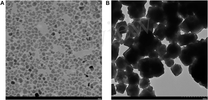
FIGURE 1. TEM images of (A) the FF and (B) the MP.
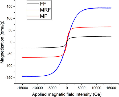
FIGURE 2. M-H curves of the FF, MRF, and MP at room temperature.
3 Theoretical basis
The main pressure capability of magnetic seals comes from the gradient of the magnetic field intensity in sealing gaps. For incompressible Newtonian steady-state flow and an irrotational flow field, the FF follows the Bernoulli equation (Rosensweig, 2013).
Where p is the pressure, ρf is the density, v is the velocity, h is the height of FFs, μ0 is vacuum permeability, M is the magnetization intensity, H is the magnetic field intensity and C is a constant. It is assumed that in static FF seals, the gravity and surface tension of FFs are neglectable, so
where Hmax and Hmin are the maximum and minimum magnetic field intensity in the sealing gap, respectively, and Ms is the saturation magnetization of the FF. Eq. 3 indicates two methods of increasing pressure capability, by improving the magnetic properties of FFs or the magnetic field.
In MRF seals, chain-like structures are formed along the magnetic field direction, and the yield stress increases significantly. Therefore, an extra portion of pressure capability comes from the elasto-plastic property of MRFs (Zhang et al., 2018)
where τ0 is the yield stress of MRFs, δ is the height of the sealing gap and b is the width of the pole tooth. The equations above are based on the Bernoulli equation, which neglects the viscosity of the fluid. In fact, the viscosity of FFs is relatively low. For example, four types of commercial FFs from Ferrotec Corp. have viscosity from 0.6 to 1.2 Pa·s at 25°C (Szczech, 2018). Therefore, the friction in static FF seals is usually neglected. On the other hand, the influence by the viscosity of MRFs under a magnetic field is represented by the yield stress.
For MP seals, the Bernoulli equation no more applies to the powdery state of the sealing medium, but the MPs in sealing gaps can be assumed to follow the principle of virtual work. For a virtual displacement of MPs, the virtual work by the pressure equals the overall change of the magnetic energy approximately. Therefore, the pressure capability is derived as (Li and Li, 2022b)
where
where α is an empirical coefficient related to the magnetic force and energy and β is an empirical coefficient related to the friction between MPs and the sealing structure. These two coefficients may be obtained by fitting sufficient amount of experimental data. ¯M is the average magnetization intensity of MPs in the sealing gap, Hr2 and Hr1 are the magnetic field intensity of the outer and inner diameter of MP rings, respectively. Hr2+Hr1 represents the average magnetic field intensity in the sealing gap, which together with ¯M is a main determinant of the magnetic force on MPs. Meanwhile, b and¯r are related to the contact area of MPs and the sealing structure. Compared to the former formula, Eq. 6 shows a better consistency with the sealing experiments below.
4 Methods
4.1 Structure design
Figure 3 shows the schematic diagram of the sealing prototype. The red circuit indicates the magnetic circuit, which is composed of a permanent magnet, two pole pieces with pole teeth on them, an inner sleeve and the magnetic medium. A certain type of magnetic medium is attracted in the sealing gaps between the inner sleeve and pole teeth. It is difficult for magnetic medium of poor fluidity to fill in the gaps uniformly, such as MPs. For the convenience of loading the magnetic medium, pole teeth are designed on the external surface of the pole pieces. In Figure 3, the sealing area is enlarged on the right, and key structural parameters are marked. In total, five pairs of pole pieces are manufactured and used. Four of them have one pole tooth per pole piece, with the height of pole tooth Lh = 2 mm and the width Lt = 0.5, 1.0, 1.5, 2.0 mm, respectively. One pair have five pole teeth per pole piece, with Lh = 2 mm, Lt = 0.5 mm and the interval between adjacent pole teeth Lm = 2.5 mm. The sealing gap is δ = 0.3 mm.
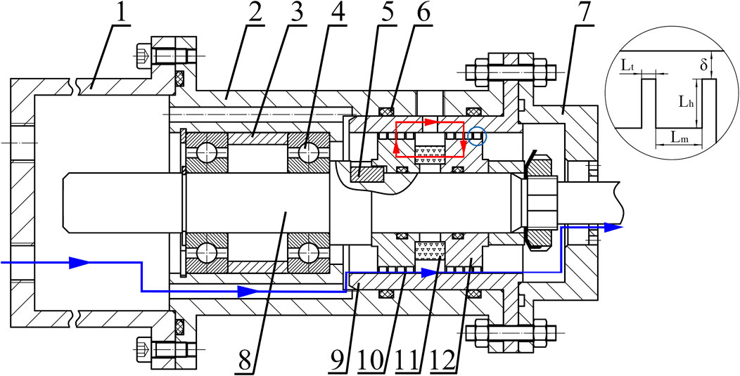
FIGURE 3. Schematic of the sealing prototype (1-gas chamber, 2-shell, 3-sleeve, 4-bearing, 5-key, 6-rubber ring, 7-cover, 8-shaft, 9-inner sleeve, 10-pole tooth, 11-permanent magnet, 12-pole piece).
The blue line in Figure 3 indicates the flow path of the sealed gas through the magnetic seal. The gas in the gas chamber is compressed slowly, and flows via two holes in the shell. For magnetic seals with a leakage rate, the gas passes through the magnetic medium and enters the atmosphere. Other paths are sealed by rubber rings. Through-holes are made on the gas chamber, the shell and the inner sleeve, so that the pressure on the first and second sealing stages can be monitored simultaneously to study the mechanism of pressure transfer among stages.
4.2 Numerical simulation
The structure of magnetic seals is a magnetostatic system with no electric currents. The solving of magnetic parameters is on the basis of Magnetic Flux Conservation and Ampere’s Law. With reference to electric circuits, the equivalent magnetic circuit of the sealing structure from Figure 3 is plotted in Figure 4. Rσ represents the total magnetic resistance of the leakage path of the magnetic flux through the air, the shaft and the shell, etc. This schematic diagram illustrates the transfer of the magnetic circuit and the loss of magnetic energy, and provides a visual guidance to the magnetic and structural design. With the definition of the demagnetizing curve of the magnet and magnetizing curves of other parts, magnetic parameters of the whole field can be calculated.
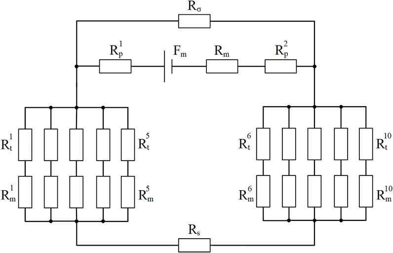
FIGURE 4. Equivalent magnetic circuit of the sealing structure. (Fm is the magnetomotive force of the magnet, and Rm, Rp, Rt, Rm, Rs, Rσ are the magnetic resistance of the magnet, pole piece, pole tooth, magnetic sealing media, shaft and magnetic flux leakage path, respectively.)
The finite element method is usually used in the simulation of magnetic field distribution. To simplify the modeling and calculating process, an axisymmetric model is applied, and only the magnetic source and magnetically conductive parts are modelled. These materials are defined by their magnetic properties (B-H curves), while others are considered to have a permeability equal to vacuum. A rectangular air domain of 80 mm width and 110 mm height is established. The axisymmetric boundary condition is applied on the symmetric axis, and the magnetic insulation boundary condition is applied on the air boundaries. The initial magnetic scalar potential is zero. The minimum meshing number in sealing gaps is 10. The tolerance set while solving the model is 0.001. After meshing and calculation, the distributions of magnetic field lines and magnetic field intensity in sealing gaps are plotted.
4.3 Experimental setups
To study the sealing performance of different magnetic seals, a sealing test bench is established in Figure 5. Key components include a sealing prototype, an air compressor, pressure sensors, valves, a computer, etc. During one experiment, a pair of pole pieces are first assembled on the shaft. The magnetic medium is injected or smeared on each pole tooth circularly, as is shown in Figure 6. Then the shaft is pushed in the shell and fixed. After the assembly of the sealing prototype and connection of electric and gas circuits, the gas is compressed by a compressor. The pressure as well as the flow rate is adjusted by a regulator valve and two ball valves before the gas chamber. The pressure on both stages of the magnetic seal is monitored and collected by pressure sensors. To test the pressure capability, the pressure in the gas chamber is elevated slowly until a sudden pressure drop occurs. For the leakage rate, the air in the gas chamber is first pressed to a certain value (20 kPa for example), and then the ball valves are turned off. The pressure drop in the next five minutes is used to indicate the leakage rate quantitatively. For each sealing condition, the experiments are repeated three times.
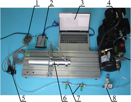
FIGURE 5. Test bench for magnetic seals (1-power supply, 2-data acquisition card, 3-computer, 4-air compressor, 5-pressure sensor, 6-sealing prototype, 7-ball valve, 8-regulator valve).
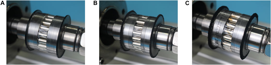
FIGURE 6. Pole teeth loaded with magnetic sealing medium (A) FFs, (B) MRFs and (C) MPs.
5 Results and discussion
5.1 Numerical simulation
Magnetic field distributions of different pole pieces are simulated separately. Each solution reaches convergence within limited steps. The results of pole pieces with five pole teeth are illustrated in Figure 7. With pole teeth acting as a concentration of magnetic lines, a large gradient of the magnetic field intensity exists under each pole tooth. The maximum magnetic field intensity in the sealing gaps is about 3.5 × 10⁵ A/m, and the minimum is 7.6 × 10⁴ A/m. However, the magnetic field under different pole teeth is not exactly the same. Sealing stages far from the permanent magnet have a slightly weaker magnetic field than those near the magnet. The possible reason is the magnetic resistance of pole pieces and the shaft in a longer magnetic circuit. In comparison, the distributions of the magnetic field intensity in sealing gaps for single pole teeth of different widths are plotted in Figure 8. The maximum magnetic field intensity varies from 5.1 × 10⁵ to 6.1 × 10⁵ A/m. The simulation results show that the maximum magnetic field intensity of the single pole tooth is larger than that of five pole teeth. The magnetic energy provided by the permanent magnet is divided among several stages. In other words, with the magnetic source fixed, increasing the number of pole teeth will lower the pressure capability of a single sealing stage.
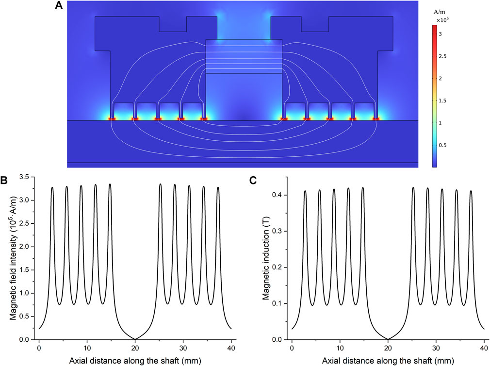
FIGURE 7. (A) Distribution of magnetic field intensity and magnetic induction lines, (B) magnetic field intensity and (C) magnetic induction in sealing gaps along the axial direction.
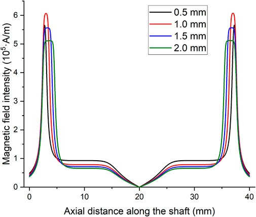
FIGURE 8. Magnetic field intensity in sealing gaps along the axial direction for single pole teeth of different widths.
5.2 Pressure capability
For FF and MP seals, a sudden pressure drop occurs at the moment of sealing failure, and the maximum pressure is regarded as the pressure capability. Pressure capability of different pole pieces is plotted in Figure 9. N is the number of pole teeth per pole piece and Lt is the width of pole teeth. The error bars represent the standard errors of three repeated experiments of the same sealing condition. In general, MP seals possess much larger pressure capability than FF seals. The main reason is the difference in the magnetization intensity. The saturation magnetization of MPs mainly depends on the mass ratio of Fe3O4 to lubricants, and it can reach to more than 60 emu/g with good dispersibility. On the contrary, to avoid sedimentation while working, the volume fraction of Fe3O4 in FFs is usually lower than 10% in practice (Parmar et al., 2018). As a result, according to Eq. 3., the pressure capability is restricted by FFs’ magnetization intensity.
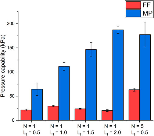
FIGURE 9. Pressure capability of FF and MP seals of different pole pieces.
Table 1 shows comparison between simulation and experimental results of different sealing structure. Because the FFs in the sealing gaps do not reach complete magnetic saturation, the integral form in Eq. 3 is adopted. For FF seals with different widths of the single pole tooth, the largest pressure capability 29.55 kPa appears at Lt = 1.0 mm, which is consistent with the trend of the maximum magnetic field intensity. Generally, a narrow pole tooth concentrates the magnetic flux better, so the magnetic field intensity is higher. However, an excessively narrow pole tooth leads to the magnetic saturation of the steel, and the magnetic field intensity decreases consequently. By using pole pieces of five pole teeth, the pressure capability almost doubles. The increasing range is moderate, partly because of the separation of the magnetic source. On the other hand, more sealing stages require more FFs and installation volume. Possible reasons for the differences between simulation and experimental results include the loss or redistribution of FFs during the assembling of sealing parts, the dimension error by manufacturing, the pressure elevating process and so on.
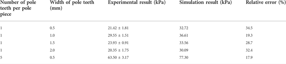
TABLE 1. Comparison between simulation and experimental results of different FF sealing structures.
For MP seals with the single pole tooth, the simulation prediction based on the previous formula Eq. 5 is compared with experimental results in Table 2. Obviously, a large deviation exists between simulation and experimental results with the present setup, and the difference decreases as the pole teeth become wider. On the one hand, Eq. 5 overestimates the pressure capability of MP seals, probably because the MPs are not packed densely or distributed uniformly in the circular direction in sealing gaps. On the other hand, pressure capability increases with the width of pole teeth, which is clearly different from FF seals. This indicates a greater influence on the pressure capability by the friction between MPs and structural parts than the magnetic field intensity. The increase by the frictional effect surpasses the decrease of the magnetic field intensity with wider pole teeth. This phenomenon cannot be fully explained by Eq. 5 from the previous study, probably because the frictional effect is intensified with narrow sealing gaps or certain types of MPs of strong friction and interparticle forces. Therefore, Eq. 6 has an additional term to describe the frictional effect. The frictional term includes the rheological and magnetic properties of MPs, the average magnetic field intensity in radial direction and the contact area. The magnetic term and the frictional term are combined by corresponding empirical coefficients, which can be obtained by fitting sufficient amount of experimental data. Based on the experimental data above, the empirical coefficients are solved as α = 2.0 × 10⁻² and β = 5.5 × 10⁻² N/(A·m)2. However, the empirical formula and coefficients require further verification by a number of experiments. For example, pole teeth with multiple widths and heights should be manufactured and tested.
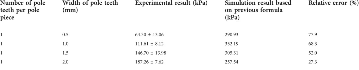
TABLE 2. Comparison between simulation based on previous formula and experimental results of different MP sealing structures.
Furthermore, the pressure capability of five pole teeth is higher than that of single pole teeth with Lt = 0.5 mm, but lower than single pole teeth with Lt = 2.0 mm. The main reason is the difficulty in the MP loading process. Due to the poor fluidity of MPs than FFs, they can hardly be distributed on pole teeth uniformly circularly. The problem is even more serious for multiple pole teeth, because the interval between pole teeth is narrow. If there is one loading deficiency on a pole tooth, the whole sealing stage loses its pressure capability. So in fact, only limited sealing stages work to resist the pressure difference. The standard errors of experimental results also show an uncertainty of the MP loading process.
An evident phenomenon of an MRF sealing failure is not observed in experiments. Unlike FFs or MPs, which have a sudden pressure drop and bursting out, MRFs cannot be pushed out of sealing gaps, and the pressure does not decrease suddenly, even when the pressure is far higher than the theoretical value. Instead, small bubbles are observed as the pressure elevates, and some carrier fluid runs away. In other words, a specific value of pressure capability does not exist, and the pressure difference only affects the leakage rate of MRF seals. As a result, the experimental results of MRF seals are not compared with Eq. 4.
5.3 Leakage rate
A significant characteristic of FF seals is their almost zero leakage, which is verified by the experiments. But for MP seals, the leakage rates can be rather large, and are affected by structural parameters. In this research, the pressure is first elevated to 20 kPa, then the inlet air is cut off. The pressure drop in the next five minutes is measured to represent the leakage rate quantitatively, as is shown in Figure 10. The leakage rate decreases with the increase of the width of the pole tooth. The form of MPs in sealing gaps is similar to porous media. While the packing structure remains unchanged, a wider pole tooth leads to a thicker powder ring, and the resistance of the leaking air increases. As a result, the leakage rate is lowered. As for multiple pole teeth, the leakage rate is even higher than wider single pole teeth. It confirms the inference above, that some sealing stages do not perform normally due to the loading difficulty.
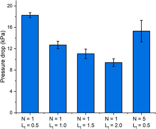
FIGURE 10. Pressure drops of MP seals of different pole pieces.
At an initial pressure of 20 kPa, MRF seals are nearly leakage-free like FFs. However, as the pressure rises, air leaking happens gradually. Figure 11 indicates the pressure changing curves of MRF seals at an initial pressure of 100 kPa. For pole pieces with five pole teeth, sealing still operates well and almost no leakage occurs. But for pole pieces with the single pole tooth, the leakage is evident and the leakage rate is higher when the pressure difference is larger. Besides, a wider pole tooth decreases the leakage rate to a great extent. It is reported by former literature that MRFs tend to form chain-like structures under a strong magnetic field, and MRFs preform solid-like characteristics as a result. When the pressure is low, the chains are pushed modestly, and magnetic particles and the carrier fluid remain great dispersibility, so the leakage rate is low. But when the pressure is high, an excessive deformation or even breakage of chains is likely to happen. The carrier fluid is deformed at the same time, because the magnetic particles are dispersed inside. As a result, small pores as leakage paths appear and expand in MRFs, instead of being pushed out of sealing gaps like FFs.
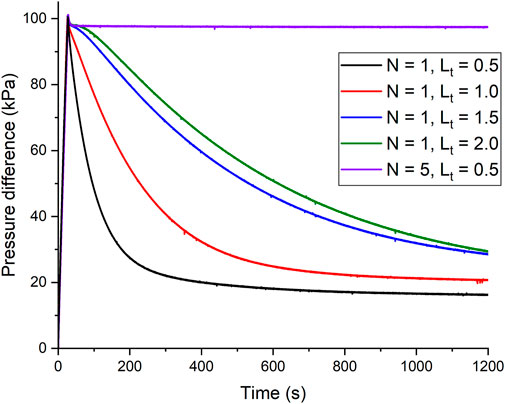
FIGURE 11. Pressure difference curves of MRF seals of different pole pieces.
5.4 Mechanism of pressure transfer and self-recovery
To study the mechanism of pressure transfer, pole pieces with single pole teeth at Lt = 1.0 mm are taken as an example, and the pressure of the inlet air remains constant. The pressure in the first and second sealing stages is monitored by two pressure sensors, respectively. As is shown in Figure 3, the first stage indicates the pressure in the gas chamber before the left pole piece, which is monitored by a pressure sensor connected to the gas chamber. The second stage indicates the pressure between the left and the right pole piece, which is monitored by the other pressure sensor connected to the shell. In other words, the pressure difference between the first and the second stage is resisted by the left pole piece, and that between the second stage and the atmosphere is resisted by the right pole piece. A simultaneous monitoring on both stages reveals the mechanism of pressure transfer.
In Figure 12A, FF seals have several obvious phases of pressure transfer. First, the first stage resists all pressure difference, and the second stage remains zero. Then several sudden increases of pressure in the second stage occur, probably because the first stage is broken through. After that, the first stage is self-recovered, until the pressure is high enough to break both sealing stages. However, after the first sealing failure, the pressure in the gas chamber is down to about 10 kPa, and the FF seal can still resist limited pressure. The pressure capability is lower, because some FFs are burst out. After the second sealing failure, the first sealing stage can hardly resist a pressure difference due to an excessive loss of FFs.
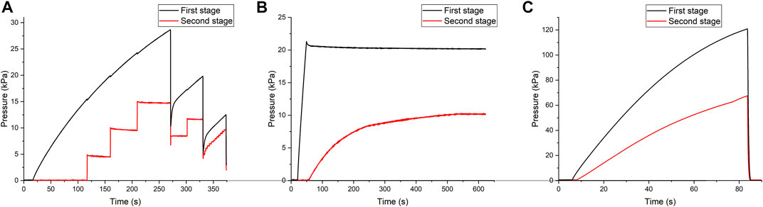
FIGURE 12. Pressure curves of two sealing stages of (A) FF, (B) MRF and (C) MP seals.
In Figure 12B, the inlet air of MRF seals is cut off after 50 s. When the pressure is rather low, only the first stage resists a pressure difference, and the second stage remains zero. But then the pressure of the second stage starts to elevate. The speed is fast but then slows down. A possible reason is that, when the pressure increases, small pores emerge as leaking paths. As the pressure of the second stage increases, former deformation of the magnetic particle chains partly recovers under the influence of the magnetic force, and the pores are self-closed, so the pressure becomes stable. The self-recovery behavior is also observed in Figure 11, where the leakage rate decreases with the descending pressure, and the pressure keeps stable in the end.
As for MP seals, the pressure distribution is average basically. The pressure of the second stage increases with the first stage from beginning, because the porous structure of MPs has an unavoidable leakage rate. Meanwhile, after the sealing failure, MPs are pushed out and cannot redistribute due to their poor fluidity. MP seals do not possess the ability of self-recovery.
6 Conclusion
This research provides a comparative study of magnetic seals by FFs, MRFs, and MPs. The formulas of pressure capability based on their different properties are derived. A sealing prototype is designed and manufactured. The magnetic field distribution is calculated by the finite element method. Finally, a test bench for magnetic seals is established, and the pressure capability, leakage rates as well as the mechanism of pressure transfer and self-recovery ability are studied. For rotating seals, this procedure is still fundamental and referable, but the influence of the centrifugal force and elevating temperature should be considered. The friction causes the rising of temperature, especially at a high speed or long working time. Consequently, the magnetization intensity of magnetic materials decreases. The characteristics of the three magnetic seals are summarized as follows:
(1) FF seals have almost zero leakage and high lifetime, which makes them the only feasible solution for specific sealing environment. Loading and supplementation of FFs are easy because of their well fluidity. However, their pressure capability is the lowest (about 10–20 kPa per stage), and the pressure transfer among stages needs time. To enhance the pressure capability, FFs of high saturation magnetization and narrow pole teeth are preferred. FF seals are suitable for sealing conditions of zero leakage, low pressure difference (typically one atmospheric pressure) and modest temperature. Potential applications include the sealing of silicon crystal growing furnaces, robot joints and so on.
(2) MRF seals do not have an evident phenomenon of sealing failure. Instead, their leakage rate rises with the elevation of pressure. After the pressure drops, the pores inside MRFs disappear, which indicates the ability of self-recovery. However, under a high pressure difference, the dispersibility of MRFs is broken, and the leakage rate is rather large. To lower the leakage rate, wide pole teeth are suggested. MRF seals are suitable for sealing conditions of high pressure (several atmospheric pressure or higher) or sudden strong impacts, and tolerance of limited gas leaking. Potential applications include magnetorheological dampers and clutches, where the same fluid is used for damping and sealing.
(3) MP seals possess much higher pressure capability than FF seals (about 50–100 kPa per stage), but the price is a high leakage rate. The pressure capability is affected by both magnetic forces and the frictional effect. Meanwhile, wider pole teeth decrease the leakage rate significantly, but multiple pole teeth are not preferred. MP seals are suitable for sealing conditions of high pressure, extreme temperature, short sealing time and tolerance of gas leaking. Potential applications include the sealing of thrust vectoring nozzles, or combination with mechanical seals. In particular, they are suitable for occasions requiring sealing and heat dissipation at the same time.
Data availability statement
The original contributions presented in the study are included in the article/supplementary material, further inquiries can be directed to the corresponding author.
Author contributions
ZL: numerical simulation, sealing experiments and manuscript. DL: material preparation, theory and supervision.
Funding
This work was supported by the National Natural Science Foundation of China (grant numbers U1837206, 51735006 and 51927810).
Conflict of interest
The authors declare that the research was conducted in the absence of any commercial or financial relationships that could be construed as a potential conflict of interest.
Publisher’s note
All claims expressed in this article are solely those of the authors and do not necessarily represent those of their affiliated organizations, or those of the publisher, the editors and the reviewers. Any product that may be evaluated in this article, or claim that may be made by its manufacturer, is not guaranteed or endorsed by the publisher.
References
Choi, S., and Han, Y. (2012). Magnetorheological fluid technology: Applications in vehicle systems. Boca Raton, Florida, United States: CRC Press.
Das, P., Colombo, M., and Prosperi, D. (2019). Recent advances in magnetic fluid hyperthermia for cancer therapy. Colloids Surfaces B Biointerfaces. 174, 42–55. doi:10.1016/j.colsurfb.2018.10.051
Fan, C., Chongfeng, Z., and Xiaolong, Y. (2021). Numerical analysis and experimental verification of magnetic fluid sealing for air cylinder in Aerospace Engineering. Int. J. Appl. Electrom. 66 (4), 581–597. doi:10.3233/JAE-201572
Huang, T., Song, F., Wang, R., and Huang, X. (2021). Numerical simulation study of tracking the displacement fronts and enhancing oil recovery based on ferrofluid flooding. Front. Earth Sci. (Lausanne). 9. doi:10.3389/feart.2021.759862
Kubík, M., Pavlí Ek, D., Machá Ek, O., Strecker, Z., and Roupec, J. (2019). A magnetorheological fluid shaft seal with low friction torque. Smart Mat. Struct. 28 (4), 047002. doi:10.1088/1361-665X/ab0834
Li, Z., and Li, D. (2022a). A novel sealing method using nano-micro magnetic powders and its leakage rate analysis. IEEE Trans. Magn. 58 (8), 1–5. doi:10.1109/TMAG.2021.3115336
Li, Z., and Li, D. (2022c). Leakage rate control of magnetic powder seals by lubricant coatings on magnetic nanoparticles and flow field simulation. IEEE Trans. Magn. 58 (8), 1–5. doi:10.1109/TMAG.2022.3144476
Li, Z., and Li, D. (2022b). Pressure capability analysis of magnetic powder seals and pole tooth design by multiparameter optimization. Powder Technol. 403, 117410. doi:10.1016/j.powtec.2022.117410
Liang, Y., Alvarado, J. R., Iagnemma, K. D., and Hosoi, A. E. (2018). Dynamic sealing using magnetorheological fluids. Phys. Rev. Appl. 10 (6), 064049. doi:10.1103/PhysRevApplied.10.064049
Liu, J., Li, D., and Zhang, Z. (2022). Experimental study and simulation on the seal pressure of a ferrofluid seal using radial-charged magnets. Front. Mat. 9. doi:10.3389/fmats.2022.879699
Matuszewski, L. (2019). New designs of centrifugal magnetic fluid seals for rotating shafts in marine technology. Pol. Marit. Res. 26 (2), 33–46. doi:10.2478/pomr-2019-0023
Parmar, S., Ramani, V., Upadhyay, R. V., and Parekh, K. (2018). Design and development of large radial clearance static and dynamic magnetic fluid seal. Vacuum 156, 325–333. doi:10.1016/j.vacuum.2018.07.055
Parmar, S., Ramani, V., Upadhyay, R. V., and Parekh, K. (2020). Two stage magnetic fluid vacuum seal for variable radial clearance. Vacuum 172, 109087. doi:10.1016/j.vacuum.2019.109087
Rosensweig, R. E. (2013). Ferrohydrodynamics. Chelmsford, Massachusetts, United States: Courier Corporation.
Szczech, M. (2018). Experimental study on the pressure distribution mechanism among stages of the magnetic fluid seal. IEEE Trans. Magn. 54 (6), 1–7. doi:10.1109/TMAG.2018.2816567
Wang, J., and Meng, G. (2001). Magnetorheological fluid devices: Principles, characteristics and applications in mechanical engineering. Proc. Institution Mech. Eng. Part L J. Mater. Des. Appl. 215 (3), 165–174. doi:10.1243/1464420011545012
Zang, G., Zhang, Z., Yu, W., Wang, D., and Li, D. (2022). Effects of different fatty acids as surfactants on the rheological properties of kerosene-based magnetic fluids. Front. Mat. 9, 334–342. doi:10.3389/fmats.2022.930633
Zhang, Y., Li, D., Chen, Y., and Li, Z. (2018). A comparative study of ferrofluid seal and magnetorheological fluid seal. IEEE Trans. Magn. 54 (12), 1–7. doi:10.1109/TMAG.2018.2868298
Keywords: ferrofluid, magnetorheological fluid, magnetic powder, seal, pressure capability, leakage rate
Citation: Li Z and Li D (2022) A comparative study of magnetic seals by ferrofluids, magnetorheological fluids and magnetic powders. Front. Mater. 9:984761. doi: 10.3389/fmats.2022.984761
Received: 02 July 2022; Accepted: 23 August 2022;
Published: 12 September 2022.
Edited by:
Yancheng Li, Nanjing Tech University, ChinaCopyright © 2022 Li and Li. This is an open-access article distributed under the terms of the Creative Commons Attribution License (CC BY). The use, distribution or reproduction in other forums is permitted, provided the original author(s) and the copyright owner(s) are credited and that the original publication in this journal is cited, in accordance with accepted academic practice. No use, distribution or reproduction is permitted which does not comply with these terms.
*Correspondence: Decai Li, bGlkZWNhaUBtYWlsLnRzaW5naHVhLmVkdS5jbg==