 Yongjian Li
 Xiaoting Liu2
95% of researchers rate our articles as excellent or good
Learn more about the work of our research integrity team to safeguard the quality of each article we publish.
Find out more
ORIGINAL RESEARCH article
Front. Mater. , 22 August 2022
Sec. Structural Materials
Volume 9 - 2022 | https://doi.org/10.3389/fmats.2022.974686
This article is part of the Research Topic Joining and Welding of New and Dissimilar Materials - Volume II View all 6 articles
Laser butt welding of thin steel sheets without filler material was widely used in many industrial fields. However, it was very difficult to focus the small laser spot on the narrow gap between the sheets during the laser butt welding process. In this study, a new method to weld thin steel sheets using a high-speed laser cladding technique is proposed. Stainless steel sheets with a thickness of 0.5 mm were welded using the high-speed laser cladding process. The results illustrated that good weld joints could be obtained without obvious cracks and pores in most of the specimens. The joints were well formed even if the sheets were not spliced together entirely. The average tensile strength of the specimens was about 500 MPa, which is almost the same as that of the substrate. The results also showed that most of the failures did not happen in the welding region, which could be concluded that the strength of joints was higher than that of the substrate. The microstructure was determined using an optical microscope (OM) and scanning electron microscope (SEM). The results showed that it may be a good choice to use the high-speed laser cladding technique for butt welding of stainless steel sheets.
Welding of lightweight materials is difficult in industrial fields (Xie et al., 2022a; Meng et al., 2021). The laser welding technique illustrated obvious advantages compared with traditional welding methods including low heat input, minimal weld distortion, and high-welding speed (Cheng et al., 2022; Khan et al., 2022; Wang et al., 2022). It was widely used in a lot of industrial fields such as welding of thin sheets (Tomashchuk et al., 2017; Gao et al., 2021; Gao et al., 2022). However, it was very difficult to focus the small laser spot on the narrow gap line between the two sheets during the laser butt welding process, and this always led to incomplete weld penetration and other defects such as gaps and pores (Ahmad et al., 2020; Chludzinski et al., 2021). The mechanical properties of the weld head were always decreased owing to those defects (Xie et al., 2022b; Liu et al., 2022; Shin et al., 2022).
In order to solve these problems, a new method for steel sheets welding using the high-speed laser cladding technique is proposed in this article. High-speed laser cladding was developed by Fraunhofer Laser Technology Research Institute, and the purpose of this technique was mainly to increase the cladding efficiency (Cui et al., 2020; Yang et al., 2021; Chen et al., 2022). High-speed laser cladding illustrated excellent advantages compared with the traditional cladding process (Zhang et al., 2013; Xiao et al., 2021; Gao et al., 2022). For example, during the traditional laser cladding process, the laser irradiated the substrate surface and created the molten pool on the surface. Therefore, part of the substrate was melted to form the pool. However, during the high speed laser cladding process, molten pool was formed upon the substrate surface; in other words, the laser beam was not directly in contact with the substrate. The melted powders were formed into small droplets and sprayed on the substrate surface to form the clad (Cheng et al., 2021; Xu et al., 2021; Meng et al., 2022). This could reduce the heat input obviously compared with the traditional laser cladding process.
However, for this article, high-speed laser cladding was used to weld the thin steel sheets, and the droplets were sprayed in the gap region between the two sheets. Weld joint was formed after the droplets filled the gap. The size of the droplets was obviously larger than the width of the gap, so the droplets were easily sprayed on the gap domain and to form the joint. Even if the gap was large or the two sheets were misplaced, the joint could be also well formed, and this was confirmed by the experiments completed in this study. According to the results, the joints also illustrated good microstructure and mechanical properties.
The metal powders used in this research were SUS316L stainless steel alloy powders with a size distribution of 50–150 μm. Figure 1 illustrates the morphology of the powders in this study. SUS304 stainless steel sheets with a thickness of 0.5 mm were used as the substrate materials in this study.
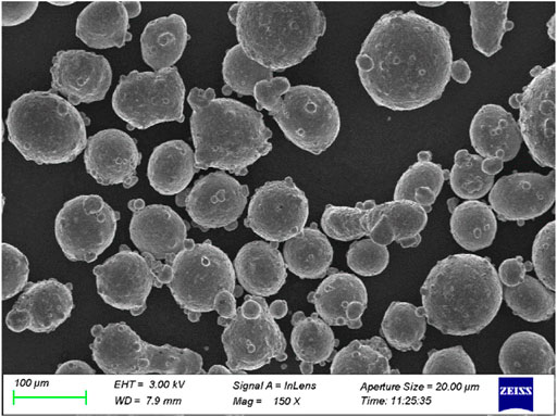
FIGURE 1. SEM micrographs of SUS316L stainless steel powders used in this research.
Two stainless steel sheets are fixed and spliced together. A fiber laser with an incident beam diameter of 1.5 mm was used to melt the powders. The melted powders were formed into the droplets, and then the droplets were sprayed on the gap region. Weld joint was formed after the droplets filled the gap. Schematic of the welding process in this study, welding fixture, and experiment system are showed in Figure 2A–C respectively. The surface of the substrate was cleaned with alcohol to remove the contaminations. In order to research the welding results under different parameters, scanning speed, laser power, and powder feeding rate were taken as the variables. Processing procedures are given in Table 1. The fracture morphology was observed using optical microscopy (OM) and scanning electron microscopy (SEM). Chemical composition was carried out using energy dispersive microanalysis (EDS).
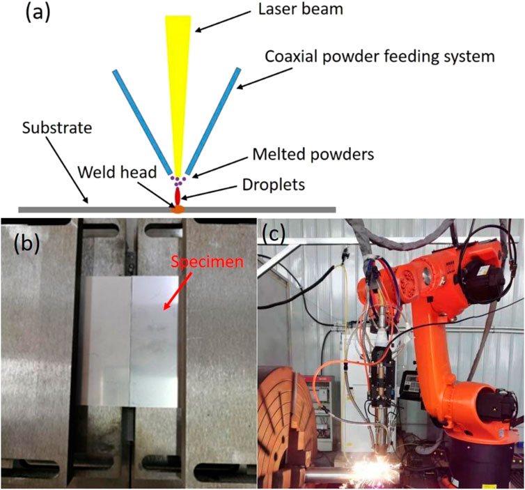
FIGURE 2. (A) Schematic of the welding process in this study, (B) welding fixture, and (C) experiment system.
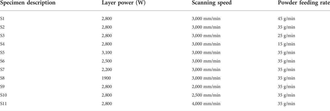
TABLE 1. Specimen designations and process conditions.
After the experiment, all the specimens were cut into small blocks by wire-electrode cutting machine for morphology observation. The specimens were polished by sand papers with 400 #–2000 #, polished using polishing cloth, and chemically etched by aqua regia to observe the microstructure. The morphological study was conducted using the optical microscope (OM) and scanning electron microscope (SEM). Tensile tests were completed on a tensile testing machine, and the sketch map of the sample is given in Figure 3.
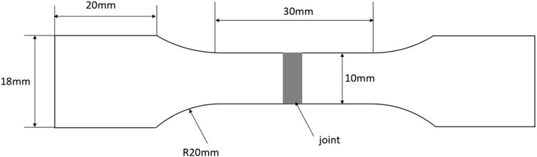
FIGURE 3. Sketch map of the tensile testing sample.
Figure 4 shows the front side and back side images of the joints under different parameters. As the figure illustrates, most of the joints show well formability, and only few specimens are burned through such as S4, S5, and S9. Heat input was one of the most important parameters, which affected the joint formability (Chukkan et al., 2015; Gou et al., 2018). When the scanning speed decreased or the laser power increased while other parameters remain unchanged, the heat input was added obviously. Therefore, the sheets were burned through. At the same time, when the powder feeding rate decreased, the powders converged to the focus of the laser beam were also decreased, and the laser beam passed through the gaps between the powders. Therefore, the substrate surface received large amount of heat input and melted quickly when the laser irradiated the substrate surface directly.
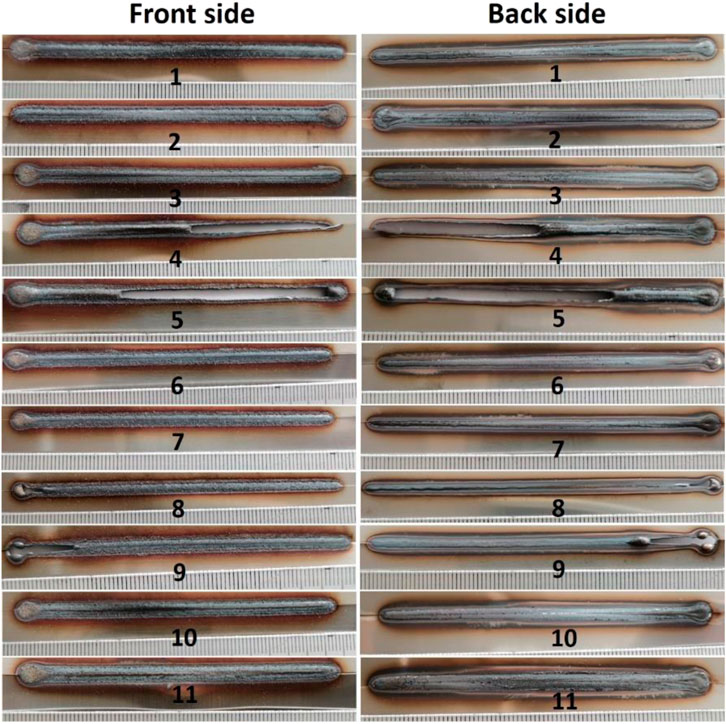
FIGURE 4. Optical microstructure of the cross section of sample 13.
Figure 5 illustrates the morphology of the cross section of the joints and the section was selected randomly along the weld line. As it can be seen from the figure, the morphology was influenced by cladding parameters obviously. When the powder feeding rate was increased, the thickness of the joint increased apparently. The thickness of the joint could also be affected by laser powder; when the power increased, the powders melted in the molten pool were also increased. Whether the two sides of the sheets were well aligned also affected the shape of the joint. However, the melted powders could fill the gap between the two sides of the sheets, and well joint formation could be achieved as specimen S10 illustrated. This was very difficult to be realized during traditional laser welding because the gap between the two sides of the sheets could cause burn through easily (Prasad et al., 2020; Kadir et al., 2021).
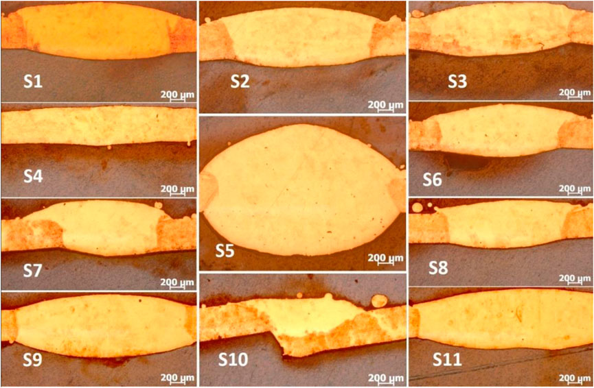
FIGURE 5. Optical microstructure of the samples.
Figure 6 shows the typical characteristics of the joint of specimen S3. Figure 6A shows microstructure near the interface region, and Figure 6B gives microstructure near the center of the weld zone. As the figure illustrates, weld zone, interface region, and substrate could be obviously found, and these regions show different microstructure characteristics. Obvious dendritic crystal characteristics could be found in the weld zone near the interface as it can be seen in Figure 6C. Figure 6D is the magnification of zone 2. These dendritic crystals grew from the interface side to the weld center. However, the center of the weld zone shows apparent peritectic crystal characteristic with the average diameter of about 10 μm. These characteristics were similar with the welded joints gained by traditional welding methods (Mishra et al., 2021).
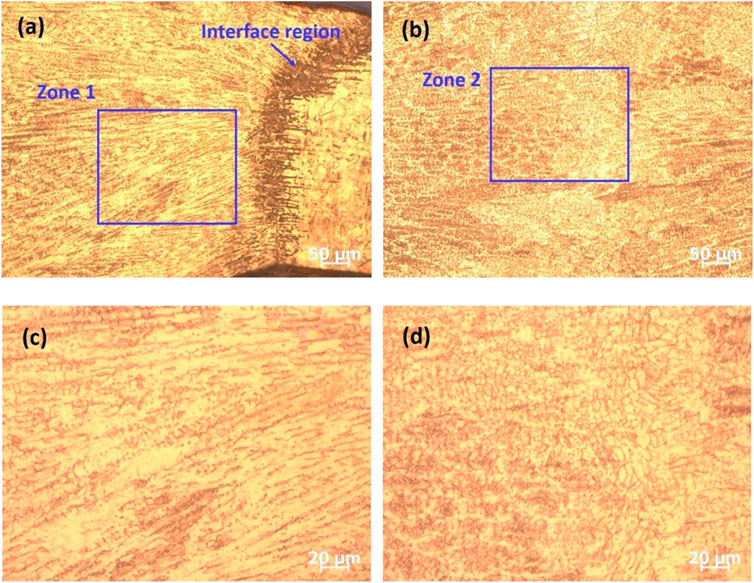
FIGURE 6. Characteristics of the weld zone: (A) microstructure near the interface region, (B) microstructure near the center of the weld zone, (C) magnification of zone 1, and (D) magnification of zone 2.
Different from the traditional laser welding process, the fusion region and heat-affected zone were very narrow owing to low heat input when using the high-speed laser cladding technique as the welding method. Figure 7 gives the typical magnification morphology of specimen S4 (Figure 7C,D), S5 (Figure 7E,F), and S11 (Figure 7A,B). The crystalmorphology could be clearly observed. It could be found that remelting happened in the interface region, and it is difficult to distinguish the fusion zone and HAZ. The width of the interface region is about 30–120 μm as the result shows, which is obviously smaller than that of the joint obtained by traditional laser welding and other arc welding methods (Harish et al., 2021). The width of the interface region is not homogeneous, and the region is always wider near the front side than the region near the back side. Laser power, powder feeding rate, and scanning speed were the important parameters to determine heat input and have an obvious influence on the width of the interface region as the figure shows. Surprisingly, when powder feeding rate was reduced, the width of the interface region also decreased obviously as Figures 7C,D shows. Incomplete fusion always occurred in the back side during the cladding process as it is showed in Figure 7A and Figure 7E.
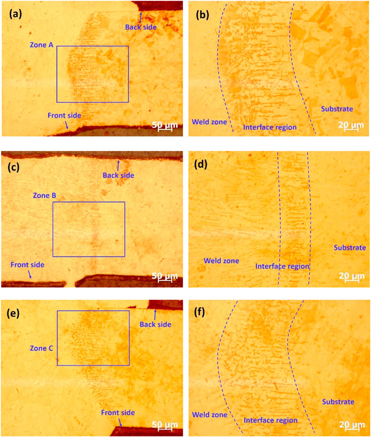
FIGURE 7. Microstructure of the interface region: (A,B) S11 (C,D) S4, and (E,F) S5.
Tensile test samples were cut from the weld specimens, and at least three samples were cut from each weld specimen. Figure 8 illustrates the specimens after tensile testing, and as it could be found in the figure, the fracture always happened in the substrate region rather than the weld zone, which means that the tensile strength of the weld zone is higher than that of the substrate. Typical engineering stress–strain curves are illustrated in Figure 9, and the numbers from 1 to 11 in the figure represent the number of the specimens. It could be obviously found that most of the test samples show a tensile strength of about 500 MPa, which was close to that of the substrate material (Shankar et al., 2016). Test sample cut from specimen S10 illustrates the highest tensile strength and the sample cut from S2 and S9 shows the highest elongation. Figure 10 illustrates the fracture surface morphology of the tensile testing samples, which failed in the substrate and weld zone, respectively. Ductile fracture could be found from the fracture characteristic, and it seems that the dimples are smaller in Figure 10C and Figure 10D. However, defects which were similar with incomplete fusion and pores in morphology could be easily found in Figure 10A and Figure 10B, which may be occurred during the tensile test.
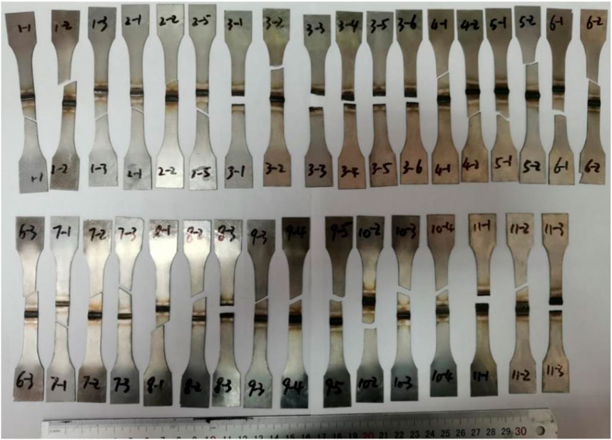
FIGURE 8. Specimens after tensile testing.
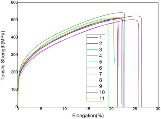
FIGURE 9. Engineering stress–strain curves of the tensile testing.
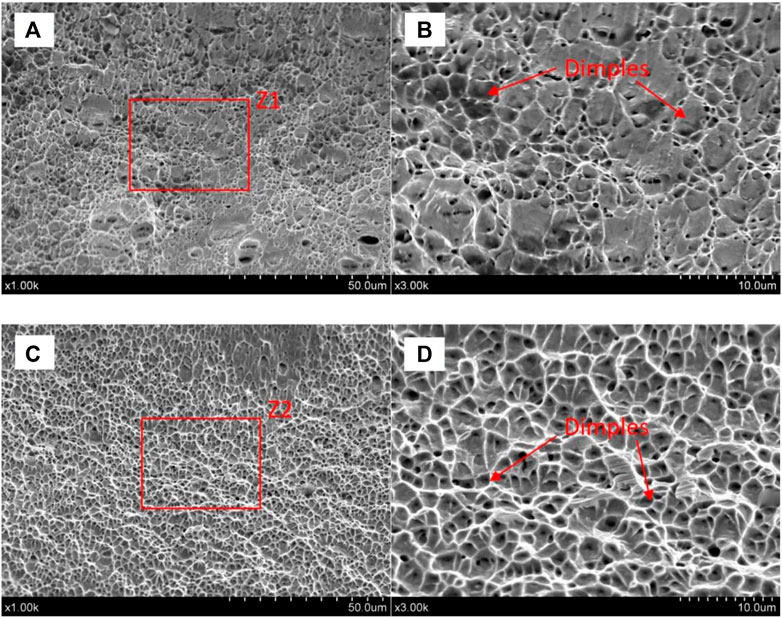
FIGURE 10. Typical fracture surface morphology of the tensile testing samples (A) fracture happened in the substrate (B) magnification of Z1 (C) fracture happened in the weld zone (D) magnification of Z2.
Cracks always happened in the interface region in the tensile test, as it was illustrated in Figure 11. EDS results showed the element distribution of the fracture region in Figure 11 and some powders were not melted completely, and this brought the inhomogeneous element distribution. Interface regions were always composed of the partly melted zone (PMZ) and heat-affected zone (HAZ), and they were typical weak regions during the welding process and cladding process. In this research article, only few specimens were cracked in the interface region, and this indicated that the strength of the interface region was higher than that of the substrate.
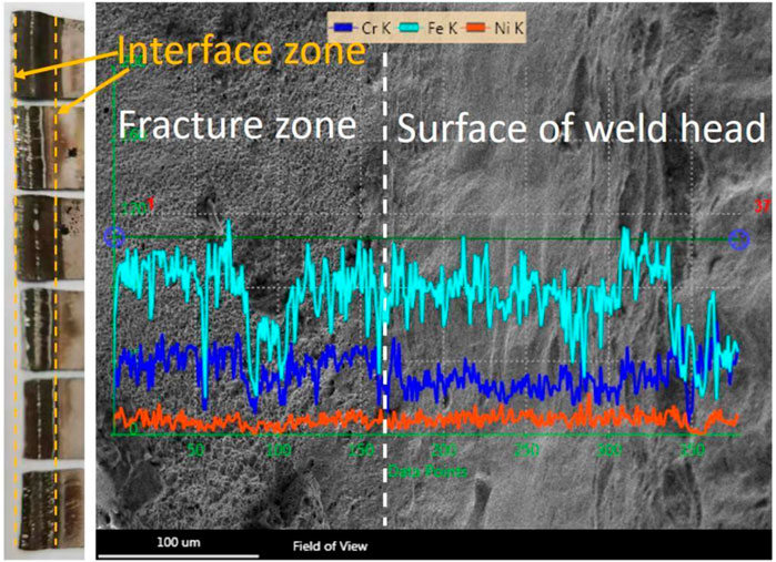
FIGURE 11. EDS analysis of the fracture region.
Welding of thin stainless sheets was completed using the high-speed laser cladding technique in this research. The following conclusions can be drawn:
1) Good jointing could be achieved in most of the specimens using the high-speed laser cladding process, and no obvious defects could be found in the joints.
2) The tensile strength of the weld zone was always higher than that of the substrate. Width of the heat-affected zone was very narrow when using the high-speed laser cladding process as the welding method.
3) The high-speed laser cladding technique could be a choice for the welding of stainless steel thin sheets.
The original contributions presented in the study are included in the article/Supplementary Material; further inquiries can be directed to the corresponding author.
YL: conceptualization, methodology, supervision, and writing; XL: OM and SEM tests; SY: tensile testing; Shiyundong: editing; and PH: editing.
We declare that we have no financial and personal relationships with other people or organizations that can inappropriately influence our work, and there is no professional or other personal interest of any nature or kind in any product, service, and/or company that could be construed as influencing the position presented in, or the review of, the manuscript entitled, “Quick butt welding of thin steel sheets using the high-speed laser cladding method.” This work was supported by the Jiangsu Agricultural Science And Technology Innovation Fund [CX(21)3152] and Postdoctoral Science Foundation of China (2020M681499).
The authors declare that the research was conducted in the absence of any commercial or financial relationships that could be construed as a potential conflict of interest.
All claims expressed in this article are solely those of the authors and do not necessarily represent those of their affiliated organizations, or those of the publisher, the editors, and the reviewers. Any product that may be evaluated in this article, or claim that may be made by its manufacturer, is not guaranteed or endorsed by the publisher.
Ahmad, G. N., Raza, M. S., Singh, N. K., and Kumar, H. (2020). Experimental investigation on Ytterbium fiber laser butt welding of Inconel 625 and Duplex stainless steel 2205 thin sheets. Opt. Laser Technol. 126, 106117. doi:10.1016/j.optlastec.2020.106117
Chen, L., Zhang, X., Wu, Y., Chen, C., Li, Y., Zhou, W., et al. (2022). Effect of surface morphology and microstructure on the hot corrosion behavior of TiC/IN625 coatings prepared by extreme high-speed laser cladding. Corros. Sci. 201, 110271. doi:10.1016/j.corsci.2022.110271
Cheng, Q., Guo, N., Fu, Y., Wang, G., Yu, M., and He, J. (2021). Investigation on in-situ laser cladding 5356 aluminum alloy coating on 5052 aluminum alloy substrate in water environment. J. Mater. Res. Technol. 15, 4343–4352. doi:10.1016/j.jmrt.2021.10.073
Cheng, Z., Du, X., Qi, B., Yuan, Z., Wu, Q., Zou, J., et al. (2022). Microstructure and mechanical properties of 3D-GH3536/R-GH3128 butt joint welded by fiber laser welding with focus rotation. J. Mater. Res. Technol. 18, 1460–1473. doi:10.1016/j.jmrt.2022.03.073
Chludzinski, M., Dos Santos, R. E., Churiaque, C., Fernandez-Vidal, S., Ortega-Iguna, M., and Sanchez-Amaya, J. (2021). Pulsed laser butt welding of AISI 1005 steel thin plates. Opt. Laser Technol. 134, 106583. doi:10.1016/j.optlastec.2020.106583
Chukkan, J. R., Vasudevan, M., Muthukumaran, S., Ravi Kumar, R., and Chandrasekhar, N. (2015). Simulation of laser butt welding of AISI 316L stainless steel sheet using various heat sources and experimental validation. J. Mat. Process. Technol. 219, 48–59. doi:10.1016/j.jmatprotec.2014.12.008
Cui, Z., Qin, Z., Dong, P., Mi, Y., Gong, D., and Li, W. (2020). Microstructure and corrosion properties of FeCoNiCrMn high entropy alloy coatings prepared by high speed laser cladding and ultrasonic surface mechanical rolling treatment. Mat. Lett. 259, 126769. doi:10.1016/j.matlet.2019.126769
Gao, Y. D., Zhang, Y., Xu, Y., and Zhou, J. (2022). The butt of CP-Ti/304 stainless steel and CP-Ti/T2 bimetallic sheets using laser-induction heating welding technology. Mat. Lett. 307, 131054. doi:10.1016/j.matlet.2021.131054
Gao, Y., Zhang, Y., Li, J., Liu, K., Xu, Y., and Zhou, J. (2021). Research on the performance of laser-MIG arc tandem welding of CP-Ti/304 stainless steel bimetallic sheets. Mat. Lett. 305, 130805. doi:10.1016/j.matlet.2021.130805
Gou, N. N., Zhang, L. J., and Zhang, J. X. (2018). Increased quality and welding efficiency of laser butt welding of 2205/X65 bimetallic sheets with a lagging MIG arc. J. Mat. Process. Technol. 251, 83–92. doi:10.1016/j.jmatprotec.2017.08.002
Harish, T. M., Peter, J., and Jerome, S. (2021). Effect of interlayer on keyhole plasma arc butt welded AISI 304H austenitic stainless steel high temperature boiler material[J]. Mater. Today Proc. 47, 4973–4977. doi:10.1016/j.matpr.2021.04.325
Kadir, M. H. A., Asmelash, M., and Azhari, A. (2021). Investigation on welding distortion in stainless steel sheet using gas tungsten arc welding process. Mater. Today Proc. 46, 1674–1679. doi:10.1016/j.matpr.2020.07.264
Khan, M. S., Ali, S., Westerbaan, D., Duley, W., Biro, E., and Zhou, Y. N. (2022). The effect of laser impingement angle on the optimization of melt pool geometry to improve process stability during high-speed laser welding of thin-gauge automotive steels. J. Manuf. Process. 78, 242–253. doi:10.1016/j.jmapro.2022.04.022
Liu, Z., Jin, X., Zhang, J., Hao, Z., and Li, J. (2022). Microstructure evolution and mechanical properties of SUS301L stainless steel sheet welded joint in ultrasonic vibration assisted laser welding. Opt. Laser Technol. 153, 108193. doi:10.1016/j.optlastec.2022.108193
Meng, L., Sheng, P., and Zeng, X. (2022). Comparative studies on the Ni60 coatings deposited by conventional and induction heating assisted extreme-high-speed laser cladding technology: Formability, microstructure and hardness. J. Mater. Res. Technol. 16, 1732–1746. doi:10.1016/j.jmrt.2021.12.110
Meng, X., Huang, Y., Cao, J., Shen, J., and dos Santos, J. F. (2021). Recent progress on control strategies for inherent issues in friction stir welding. Prog. Mat. Sci. 115, 100706. doi:10.1016/j.pmatsci.2020.100706
Mishra, D., Rajanikanth, K., Shunmugasundaram, M., Kumar, A. P., and Maneiah, D. (2021). Dissimilar resistance spot welding of mild steel and stainless steel metal sheets for optimum weld nugget size. Mater. Today Proc. 46, 919–924. doi:10.1016/j.matpr.2021.01.067
Prasad, S., Pal, S., and Robi, P. S. (2020). Analysis of weld characteristics of micro plasma arc welded thin stainless steel 306 L sheet. J. Manuf. Process. 57, 957–977. doi:10.1016/j.jmapro.2020.07.062
Shankar, V., Mariappan, K., Sandhya, R., and Laha, K. (2016). Understanding low cycle fatigue and creep–fatigue interaction behavior of 316 L (N) stainless steel weld joint. Int. J. Fatigue 82, 487–496. doi:10.1016/j.ijfatigue.2015.09.003
Shin, J., Kang, S. G., Hyun, K., and Ji, H. (2022). In-depth characterization of an aluminum alloy welded by a dual-mode fiber laser. J. Mater. Res. Technol. 18, 2910–2921. doi:10.1016/j.jmrt.2022.03.187
Tomashchuk, I., Sallamand, P., Méasson, A., Cicala, E., Duband, M., and Peyre, P. (2017). Aluminum to titanium laser welding-brazing in V-shaped groove. J. Mat. Process. Technol. 245, 24–36. doi:10.1016/j.jmatprotec.2017.02.009
Wang, H., Xie, J., Chen, Y., Liu, W., and Zhong, W. (2022). Effect of CoCrFeNiMn high entropy alloy interlayer on microstructure and mechanical properties of laser-welded NiTi/304 SS joint. J. Mater. Res. Technol. 18, 1028–1037. doi:10.1016/j.jmrt.2022.03.022
Xiao, M., Gao, H., Sun, L., Wang, Z., Jiang, G., Zhao, Q., et al. (2021). Microstructure and mechanical properties of Fe-based amorphous alloy coatings prepared by ultra-high speed laser cladding. Mat. Lett. 297, 130002. doi:10.1016/j.matlet.2021.130002
Xie, Y., Meng, X., Chang, Y., Mao, D., Qin, Z., Wan, L., et al. (2022a). Heteroatom modification enhances corrosion durability in high‐mechanical‐performance graphene‐reinforced aluminum matrix composites. Adv. Sci., 2104464, 1–9. doi:10.1002/advs.202104464
Xie, Y., Meng, X., and Huang, Y. (2022b). Entire-process simulation of friction stir welding—Part 1: Experiments and simulation. Weld. J. 101 (5), 144–159. doi:10.29391/2022.101.011
Xu, Q. L., Liu, K. C., Wang, K. Y., Lou, L. Y., Zhang, Y., Li, C. J., et al. (2021). TGO and Al diffusion behavior of CuAlxNiCrFe high-entropy alloys fabricated by high-speed laser cladding for TBC bond coats. Corros. Sci. 192, 109781. doi:10.1016/j.corsci.2021.109781
Yang, J., Bai, B., Ke, H., Cui, Z., Liu, Z., Zhou, Z., et al. (2021). Effect of metallurgical behavior on microstructure and properties of FeCrMoMn coatings prepared by high-speed laser cladding. Opt. Laser Technol. 144, 107431. doi:10.1016/j.optlastec.2021.107431
Keywords: high-speed laser cladding, tensile strength, microstructure, butt welding, steel sheets
Citation: Li Y, Liu X, Yan S and He P (2022) Quick butt welding of steel sheets using the high-speed laser cladding method. Front. Mater. 9:974686. doi: 10.3389/fmats.2022.974686
Received: 21 June 2022; Accepted: 11 July 2022;
Published: 22 August 2022.
Edited by:
Shude Ji, Shenyang Aerospace University, ChinaReviewed by:
Hongbo Xia, Yangzhou University, ChinaCopyright © 2022 Li, Liu, Yan and He. This is an open-access article distributed under the terms of the Creative Commons Attribution License (CC BY). The use, distribution or reproduction in other forums is permitted, provided the original author(s) and the copyright owner(s) are credited and that the original publication in this journal is cited, in accordance with accepted academic practice. No use, distribution or reproduction is permitted which does not comply with these terms.
*Correspondence: Yongjian Li, aGl0bHlqQHVqcy5lZHUuY24=
Disclaimer: All claims expressed in this article are solely those of the authors and do not necessarily represent those of their affiliated organizations, or those of the publisher, the editors and the reviewers. Any product that may be evaluated in this article or claim that may be made by its manufacturer is not guaranteed or endorsed by the publisher.
Research integrity at Frontiers
Learn more about the work of our research integrity team to safeguard the quality of each article we publish.