 Xin Feng
 Liangliang Zhang
 Zhaowei Zhu1
94% of researchers rate our articles as excellent or good
Learn more about the work of our research integrity team to safeguard the quality of each article we publish.
Find out more
ORIGINAL RESEARCH article
Front. Mater. , 26 September 2022
Sec. Mechanics of Materials
Volume 9 - 2022 | https://doi.org/10.3389/fmats.2022.963149
This article is part of the Research Topic Multi-field Coupling Mechanics of Smart Materials and Structures View all 6 articles
The tremendous attention of researchers has been attracted to the unusual properties of quasicrystals in coatings. In this paper, the exact solutions of the functionally graded multilayered two-dimensional quasicrystal coating structures in a thermal environment are derived for advanced boundary-value problems with mixed boundary conditions. The state space method is formulated to the thermal coupling with quasicrystal linear elastic theory that derives the state equations for functionally graded quasicrystal coating structures along the thickness direction. The mixed supported boundary conditions in the x-direction and the simply supported boundary conditions in the y-direction are subjected to time-harmonic temperature loadings, which are represented by means of the differential quadrature technique and Fourier series expansions, respectively. Traction on both the bottom and top surfaces is free, and perfect thermal and mechanical contacts between constituents are incorporated at the internal interfaces. A global propagator matrix, which connects the field variables at the top interface to those at the bottom interface for the whole coating structure, is further completed by joint coupling matrices to overcome the numerical instabilities. Finally, three application examples are proposed to throw light on various effects of the power law index, frequency, and different boundary conditions on the field variables in three-layer coating structures. The present solution can serve as a benchmark for the modeling of functionally graded quasicrystal coating structures based on various numerical methods.
Multilayered quasicrystal (QC) composites possess huge potential applications in the aeronautical and aerospace industries, manufacturing of semiconductor and electrical devices as well as some modern high-technology sectors due to their unique quasi-periodic structure and excellent physical properties (Fan, 2011; Guo et al., 2020). In addition, due to the high hardness, good chemical stability, high temperature resistance, and corrosion resistance of QC materials, QC coating technology has been tremendously developed (Beardsley, 2008; Mora et al., 2020), which proposed new ways to improve the aeroengine performance. Compared with monolithic samples, artificially designed layered QC coating structures can provide better combinations of strength and ductility, strength-to-weight ratios, and stiffness-to-weight ratios. Meanwhile, the temperature deformation and thermal stress of the plates and coatings are also important factors that must be considered in the engineering structure design. Thus, the responses of the QC composite material structure in the thermal environment have always been a research hotspot, including static response [residual stress caused by high temperature (Polishchuk et al., 2012)], steady state response [stress problem in the heat insulation process (Li and Liu, 2018)], and dynamic response (instantaneous thermal stress in the impact state).
In addition, QC materials as multilayered structures have some weaknesses, such as they may crack at low temperature or peel off at high temperature, which will reduce the life-time and reliability of the devices. For instance, QC composite thermoelectric converters are exposed to thermal environments, including severe temperature gradients, which can generate interlayer thermal stresses that affect the structure in practice (Maciá, 2004). Thus, in order to improve thermal and mechanical material properties, various kinds of models have been proposed to overcome these cark and problems. Li (2013) and Li et al. (2015) obtained the fundamental solutions for the one-dimensional (1D) QC medium subjected to two identical thermal loadings on the upper and lower crack lips. Under surface heat loadings, the interlayer stress for 1D hexagonal piezoelectric QC simply supported nanoplate (Zhang et al., 2019) decreases continuously with the increase of the functional gradient factors. Based on the QC nonlocal theory, Yang et al. (2018) obtained the thermo-elastic analysis solution for the two-dimensional (2D) QC simply supported nanoplates subjected to a temperature change. According to the pseudo-Stroh formalism, the deformation of a conductive elliptic hole embedded in the 2D decagonal QC plane (Guo et al., 2016) was derived under a remotely uniform heat flow. In addition, the case of the thermal conductivity measurement along with periodic and quasi-periodic directions in decagonal QCs (Matsukawa et al., 1999; Dolinsek, 2012) and the thermo-elastic response of 2D QC plates (Yang et al., 2014; Huang et al., 2021) were investigated.
For many years there has been considerable interest in the static and dynamic response in multilayered crystal and QC media due to its many applications in composite materials, nondestructive evaluation, geophysics, surface acoustic wave devices, etc. (Bak, 1985a). The propagator matrix method is one of the most effective methods to analyze these media (Huang et al., 2019). The exact solutions of vibration frequency (Sun et al., 2021) and buckling load (Zhang et al., 2022) for 2D decagonal QC multilayered nanoplates can be derived by using the propagator matrix method, which connects the field variables at the upper and lower interfaces of each layer. However, propagator matrix method implementation may suffer from numerical instabilities (Chen et al., 2003; Lü et al., 2006) when the frequency is high, the thickness is large, and the discrete point number exceeds a certain value for the differential quadrature methods (DQM). Various techniques and methods have been proposed to overcome this problem of the propagator matrix method. Dunkin (1965) derived the delta operator technique to alleviate the problem for isotropic materials. Although this method has been developed for the anisotropic material (Castaings and Hosten, 1994), it requires the computation of large-order delta matrices. In addition, Mal (1988) presented the direct global matrix method by reducing the transfer distance. But this method occupied substantial memory storage and computation time. After that, an improved recursive algorithm of the stiffness matrix method (Tan, 2006; Tan, 2011) is presented for computing both total and surface stiffness matrices for a general multilayered anisotropic media. Different from the stiffness matrix method, the traditional propagation matrix method was firstly used to continuously connect the interface variables for multilayered plates with perfect/imperfect interfaces, which is further completed by the dual variable and position technique (Li et al., 2021; Vattré et al., 2021; Vattré and Pan, 2021) to improve the stability of frequency calculation. According to the continuity conditions, one stable approach that involves joint coupling matrices (Lü et al., 2008) is used to deal with the perfect and imperfect interfaces.
As reviewed above, previous analyses for the thermoelastic QC multilayered structure have been conducted under the assumption of static deformation, within which the exact solutions have been evaluated for models with simply supported boundary conditions only. In this paper, forced vibration analysis is carried out on the thermoelastic, anisotropic, multilayered, and inhomogeneous QC coating structures with mixed supported boundary conditions. DQM is utilized to simulate the simply and/or clamped supported boundary conditions along the x-direction, and the Fourier series expansion as the exact closed-form solutions are used to satisfy the boundary conditions in the y-direction. In addition, the basic equations of QC material are converted into the state equations composed of partial differential by utilizing the state-space method. A global propagator matrix is derived by joint coupling matrices to overcome the numerical instabilities. Finally, the typical numerical examples are presented to verify the effectiveness of this method, and the results are very useful for the design and understanding of the characterization of the functionally graded (FG) QC materials in their applications to multilayered systems.
Figure 1A presents the three-dimensionless multilayered QC thermal barrier coating structure model that is composed of M-bonded orthotropic, linearly thermoelastic, and FG layers. The relationship between the global Cartesian coordinate system and the local material coordinate system of this model is assumed to be (x, y, z) = (x1, x2, x3). The arbitrary, finite, and inhomogeneous pth layer (p = 1, 2, 3, …, M) is surrounded by zp and zp-1 interfaces, respectively, and the in-plane x - and y -directions are aligned with the horizontal edges of the mode boundaries. In addition, the corresponding thickness is hp = zp − zp−1. It also follows that the bottom and top surfaces of the laminate are z0 = 0 and zM = H, respectively.
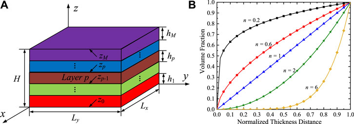
FIGURE 1. (A) An M-layered FG 2D QC structure. (B) Material property variation in terms of volume fraction of exterior material.
Figure 1B describes the variation of the material properties in terms of the volume fraction of external material along the z-direction for pth layer. The pth layer FG material properties vary along the thickness direction, and they can be a combination of 2D QC materials. According to the multilayered structure theory, the pth layer can be divided into arbitrary mathematical layers along the thickness direction. For the material property distribution, the corresponding models are taken as (Saviz, 2017)
where F(z) is the material property; n is the non-negative power-law index.
In this part, the material local coordinate system (x1, x2, x3) is utilized to describe the basic equations of 2D decagonal QC materials. To simplify the formula, the non-negative power-law index is taken as n = 1 in the following equations. QCs exhibit symmetries that are contradictory to the classical crystalline law of symmetry (Fan, 2011). Two different elementary excitations are associated with atomic motion in QCs (Hu et al., 2000; Fan, 2011): phonon and phason. Phonon displacements ui (i = 1, 2, 3) are related to the translation of atoms whereas phason displacements wk (k = 1, 2) are related to atomic rearrangements along the quasiperiodic direction. Both displacement fields are needed in the analysis of QCs and are actually coupled with each other. Based on the fundamentals of QC linear elastic theory (Hu et al., 2000), the generalized relationship of strain-displacement for 2D QCs is
where j = 1, 2, 3. εij and wkj are the strains in the phonon and phason fields, respectively. The subscript comma denotes the partial differentiation with respect to the axis.
Based on Newton’s second law, the first equation of motion in Eq. 3 is related to phonon equilibrium equations. According to the structural fluctuations attributed to phonon-phason coupling, the second equation in Eq. 3 follows Bak’s model (Bak, 1985a; Bak, 1985b), as follows
where σij denote the phonon stresses and Hkj are the phason stresses; ρ is the mass density.
According to the conventions in crystallography, all the elastic properties and thermal expansion properties possess intrinsic centrosymmetry (Hu et al., 2000). Thus, the constitutive equations with nonlocal and thermal effects for 2D decagonal QCs with point groups 10 mm, 1,022,
where C11, C12, C13, C33, C44 are the elastic constants with the relationship 2C66 = C11 − C12 in the phonon field; K1, K2, K4, and R1 represent the phason elastic constants, and phonon-phason coupling elastic constants, respectively; βi are the thermal constants with β1 = β2; T represents the variation of the temperature.
According to the heat conduction theory, the relationships of the heat fluxes qi and the temperature T (Yang et al., 2014) are
where k11, k22, and k33 represent the thermal conductivity coefficients.
Based on the Green–Naghdi generalized thermoelastic theory (Al-Qahtani and Datta, 2004), the extended dynamic equations for QC thermoelastic plate in the absence of heat generations (Yang et al., 2018) are
where T0 is the environmental temperatures and Ce denotes the specific heat capacity at constant strain.
The Cartesian coordinate system (x, y, z) is utilized to describe the dynamic response of multilayered QC structures. Substituting Eq. 5 into Eq. 6, the use of the principle of conservation of energy obtains, as follows
According to the state-space method and multilayered structure theory (Huang et al., 2019), the temperature T and heat flux qz in Eq. 7 can be taken as the state variables. Thus, substituting Eqs 2, 4 into Eq. 3 and combined with Eq. 7, the state equations can be derived in matrix forms as
where θ1(x, y, z, t) = [ux, uy, wx, wy, σzz, T, σxz, σyz, Hxz, Hyz, uz, qz]T is called the basic variables, in which the superscript “T” denotes transpose, and the state transition matrix A is
The submatrices A1 and A2 in Eq. 9 are
where the coefficients in Eq. 10 are written as follows
The eliminating in-plane variables θ2(x, y, z, t) = [σxx, σyy, σxy, Hxx, Hyy, Hxy, Hyx, qx, qy]T can be expressed as
with b4 = K2.
For the rectangular composite materials with ideal constraints at the edges, Simply supported (S), Clamped supported (C), and zero temperature boundary conditions are listed in the x- and y-directions as follows
where “S” indicates the simply supported boundary condition and “C” is the clamped supported boundary condition. For example, “CSCS” denotes the model with the clamped supported boundary conditions at x = 0 and x = Lx, and others are simply supported boundary conditions at y = 0 and y = Ly, respectively.
For the simply supported boundary conditions of the FG 2D QC coating structures in the y-direction, the Fourier series is sufficiently general to obtain the solutions, as follows
where ω is the angular frequency, and imaginary i =
Incorporating Eq. 14 with Eqs 8, 12 yields
where
Although the Fourier series can be used to satisfy the simply supported boundary conditions in the y-direction, the coating structures with the clamped supported and mixed boundary condition cannot be solved in the x-direction. Here, DQM is used to deal with this problem. DQM is a numerical method for solving ordinary differential, partial differential, integral, and integrodifferential equations. And DQM has been approved as highly efficient for the rapid solution of various typical boundary value and initial value problems (Lü et al., 2008).
In this paper, Eq. 15 are dispersed using DQM to separate the dependence on them to the x-direction and convert the partial differentials Eq. 15 into ordinary differential equations. Here, the Chebyshev-Gauss-Lobatto grid space model (Lü et al., 2006) is adopted in the in-plane discrete direction
where N is the number of sampling points.
Based on the DQM, Eq. 15 can be rewritten as
where
For a special problem, the boundary conditions should also be incorporated into the state Eq. 17 so as to obtain the solution. Two typical supporting conditions at x = 0 and x = Lx can be rewritten as
where d = 1 or N.
However, the phonon and phason stress boundary conditions
For the pth layer, the state Eq. A1 that satisfies the corresponding boundary conditions can be written as the following unified matrix form
where
According to the theory of ordinary differential equation, the solutions of Eq. 21 are derived at the upper and lower interfaces of the pth layer
Let
where
Similarly, we get
Assume that the interface zp is formed by bonding the upper surface
The field variables are assumed to be continuous, so the interface conditions are as follows
where the superscripts “+” and “−” are defined as variables on the upper surface of the pth layer and variables on the lower surface of the (p + 1)-th layer, respectively.
However, if the thickness hp (z − zp) in Eq. 22 is large, or the coefficient matrix T(p) exists maxima or minima values, numerical instability will be encountered. In addition, when it comes to the cases of high-order frequencies and large discrete point numbers (Chen et al., 2003; Lü et al., 2006), the numerical instabilities will also arise by the conventional propagator matrix M(p) (hp) in Eq. 23. Several methods have been developed to deal with this numerical difficulty. In this section, based on the joint coupling matrices (Lü et al., 2008), a new transfer relation is established to resolve this problem.
According to interface conditions, field variables can be rewritten as
where Jc = [I, −I] is the joint coupling matrix at the interface zp, and
Similarly, we can obtain the relationship of the top and bottom surfaces for the whole QC model, as follows
where Jt = Jw = [I, 0], and
It is assumed that the mechanical boundary conditions on the top and bottom surfaces of the model are zero, and a top surface harmonic heat temperature is considered, i.e.,
where
with temperature amplitude Ts.
where
τ can be rewritten as
The whole structure can be defined as
where
Substituting Eq. 34 into Eq. 31 results in
Eq. 36 can be rewritten as
where the superscript “−1” represents the inverse of the matrix.
Using Eqs 37, 18, the forced vibration solutions of the whole QC coating structure are obtained.
Typical illustrative examples of the fully coupled thermoelasticity theory in multilayered QC structures are provided for forced vibration analysis. The multilayered FG QC coating model is composed of three single layers of the same thickness, and the dimensions of this laminate are Lx × Ly × H = 1 mm × 1 mm × 0.3 mm. Two kinds of QC materials (called QC1 and QC2) are considered for every single layer, and the thermoelasticity material properties of QC1 (top) and QC2 (bottom) are listed in Table 1. And two kinds of material parameters completely match the elastic deformation energy density of the QC (Hwu, 2010; Fan, 2011), so they can be used to calculate the relative changes of the dynamic analysis for the 2D FG QC structures. In addition, the temperature amplitude Ts is taken as 1 K. The following discussions are based on calculations with l = 1, and the discrete points are taken as N = 25. For the convenience of expression, the natural frequencies of the layered structures are considered to be dimensionless as Ω = ωLmax/
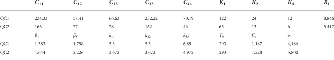
TABLE 1. Material properties (C, K, and R in 109 N/m2, β in 106 N K/m2, k in W K/m, T0 in K, Ce in J kg/K, ρ in kg/m3).
It is assumed that the tractive force and harmonic heat temperature on the top and bottom surfaces of the model are zero. The first-order dimensionless natural frequencies Ω for the QC1/QC1/QC1 plate with boundary conditions SSSS is Ω = 0.33471. In order to the resonance of the QC laminates, the dimensionless frequencies for force vibration response are taken as Ω = 0.05, 0.1, 0.15, and 0.2. It is noted that the static closed-form solutions of this model can be obtained at Ω = 0.
One numerical example of the QC plate with the boundary condition SSSS to verify the validity and accuracy of the proposed method and the numerical solution is presented in Figure 2. The material parameters, the shape and size of the plate, the quasicrystal quasi-periodic direction, and the mechanical quantities used are consistent with those in Ref. (Yang et al., 2018). The phonon and phason displacements and stresses uy, wy, σyy, and Hyy are normalized by their maximum values among these four variables along the thickness direction. The results obtained by the pseudo-Stroh formalism (Yang et al., 2018) and the presented method are consistent. This feature indicates that the method in this paper has high precision and good convergence and the solutions are stable.
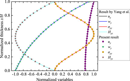
FIGURE 2. Normalized displacements and stresses for the QC plate.
In this part, the solutions of the FG QC coating structures with boundary conditions CSCS are presented. The power law index is set as n = 0.2, 0.6, 1, 2, and 6. The frequency is taken as Ω = 0.1. The horizontal coordinate is fixed at (x, y) = (0.25Lx, 0.75Ly).
Figure 3 illustrates the effects of the power law index n on the phonon and phason displacement components of the structures along the thickness direction. Regarding the displacement solutions induced by the time harmonic temperature loadings only, where a complete reversal variation of uy and wy occurs in Figures 3A,D with increasing n, both displacement components are sensitive to n. The distribution of uz (Figure 3B) internal model is nonlinear rather than functional, which is consistent with the elastic theory of models. wx (Figure 3C) are more sensitive to n than wy, and the value of wx is greater than that of wy.

FIGURE 3. Variation of the phonon and phason displacements for QC coating structures: (A) ux, (B) uz, (C) wx, and (D) wy.
Figure 4 illustrates the effects of the power law index n on the phonon and phason stress components of the QC coating structures along the thickness direction. The solution strictly satisfies the basic equation of 2D QC material, and the distributions of field variables at any position of the multilayered structure can also be presented. Since each layer of the coating structure is inhomogeneous, the distributions of σyz and σzz along the z-direction are not symmetrical in Figures 4A,B. σxy, Hyx, and Hxy (Figures 4C,E,F) are similar between layers, which are discontinuous between internal interfaces. Based on the classic elasticity theory, only the local stress of the basic equation of the QC is considered. But in fact, the stress state also includes the strong interlayer stress between the interfaces. The high-interlayer stress is considered to be one of the special failure mechanisms of composite materials in engineering applications. In addition, if the material properties at the interfaces are the same, these stresses are continuous for these structure models. The distribution of Hyz (Figure 4D) is nonlinear, and the value is zero at the external surfaces. For the above physical variables, if DQM will be also utilized to discretize domains along the y-direction, the superposition l will not appear in the formulations of the exact solution.
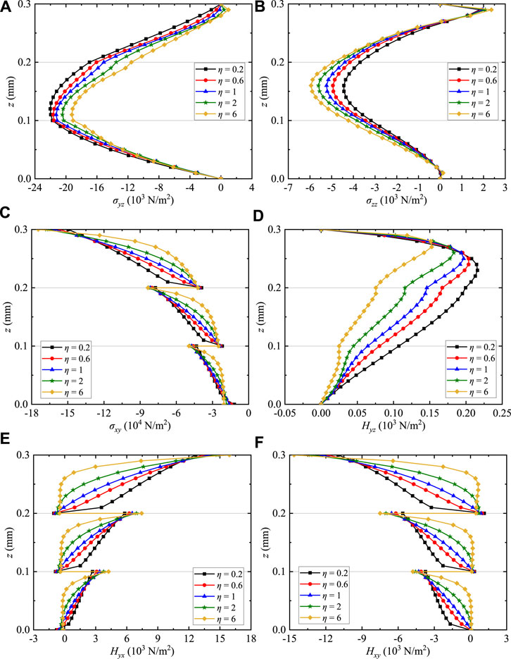
FIGURE 4. Variation of the phonon and phason stresses for QC coating structures: (A) σyz, (B) σzz, (C) σxy, (D) Hyz, (E) Hyx, and (F) Hxy.
Figure 5 illustrates the effects of the power law index n on the temperature and heat flux of the QC coating structures along the thickness direction. The vertical heat flux qz (Figure 5B) for multilayers is more sensitive to n than the temperature T (Figure 5A). This feature is attributed to qz which is affected by a linear material constant k33 in Eq. 5. In addition, n has a significant effect on qz and does not change its magnitude and direction at the top and bottom surfaces of the QC coating structures.
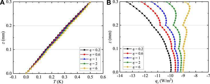
FIGURE 5. Variation of the temperature and heat flux for QC coating structures: (A) T and (B) qz.
In this part, the solutions of the FG QC coating structures with boundary conditions CSSS along the thickness direction are presented. The power law index is set as n = 1. The frequencies are taken as Ω = 0.05, 0.1, 0.15, and 0.2.
Figures 6–8 present the contour plots of uz, wx, and wy for the coating structures on the x-z plane with y = 0.75Ly, respectively. The maximum magnitudes of uz (Figures 6A–D), wx (Figures 7A–D), and wy (Figures 8A–D) exist near the top surface and increase with the increase of Ω. And Ω has a slight effect on uz, wx, and wy. Due to the gradient distribution of the material within the coating structures, the variation of these displacements of this model is not symmetric at x = 0.5 mm. Different from uz and wy, the value of wx is not zero at x = Lx. This feature is consistent with the linear elastic theory of models. In addition, the variation of uz, wx, and wy can also prove that the values of any position in the model can be obtained.
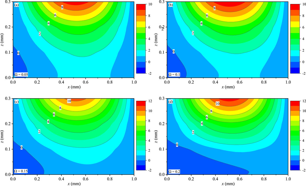
FIGURE 6. Effect of Ω on the phonon displacement uz (10−7 mm): (A) Ω = 0.05, (B) Ω = 0.1, (C) Ω = 0.15, and (D) Ω = 0.2.
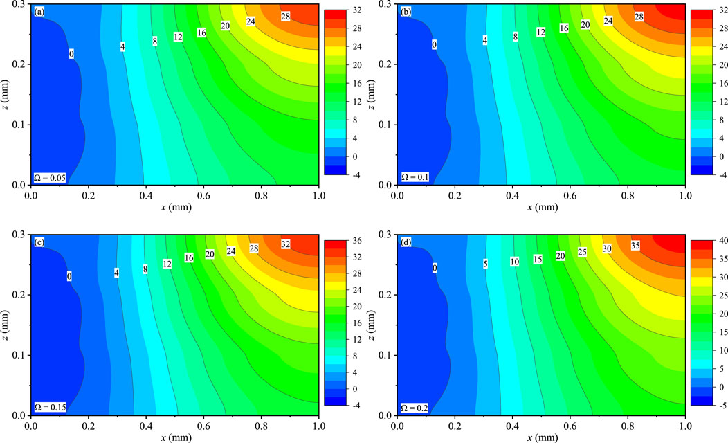
FIGURE 7. Effect of Ω on the phason displacement wx (10−9 mm): (A) Ω = 0.05, (B) Ω = 0.1, (C) Ω = 0.15, and (D) Ω = 0.2.
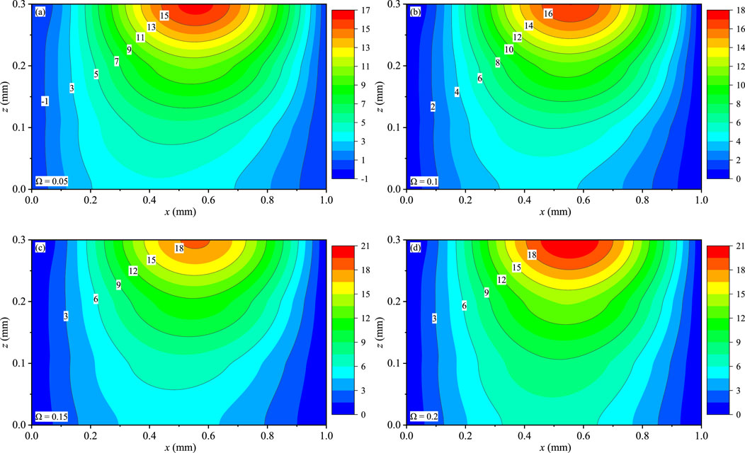
FIGURE 8. Effect of Ω on the phonon displacement wy (10−9 mm): (A) Ω = 0.05, (B) Ω = 0.1, (C) Ω = 0.15, and (D) Ω = 0.2.
Figures 9–11 present the contour plots of T, qx, and qy for the coating structures on the x-z plane with y = 0.75Ly, respectively. The distributions of T, qx, and qy are symmetric at x = 0.5 mm, and these variables are not affected by boundary conditions. T (Figures 9A–D) and qx (Figures 10A–D) obviously change with the different Ω, and they are slightly sensitive to the values of Ω. qx and qy (Figures 11A–D) are discontinuous at the internal interfaces, and interlaminar heat fluxes are little affected by Ω. Interlaminar thermal stress and interlaminar heat fluxes are attributed to the thermophysical and mechanical properties mismatching between the sublayers of the QC coating structures under the time-harmonic temperature loadings, which would inevitably involve interlayer failure of the laminate and reduce the carrying capacity.
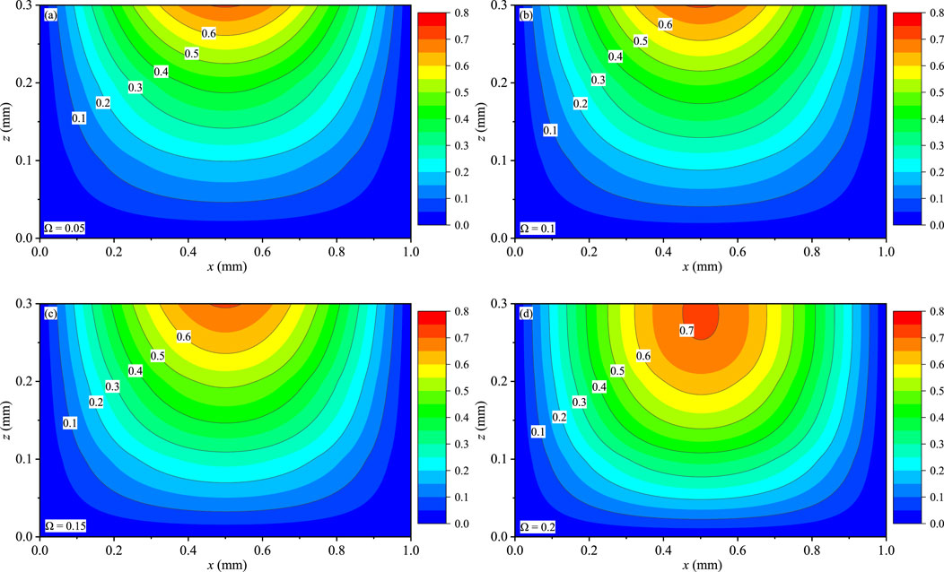
FIGURE 9. Effect of Ω on the temperature T (K): (A) Ω = 0.05, (B) Ω = 0.1, (C) Ω = 0.15, and (D) Ω = 0.2.
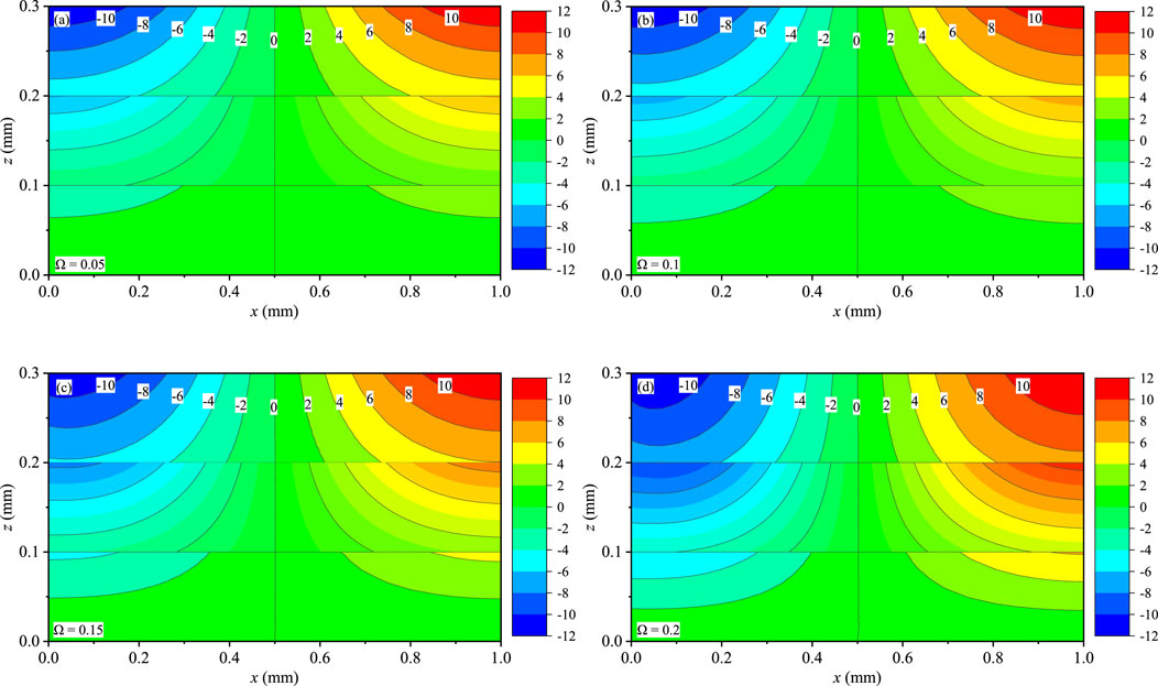
FIGURE 10. Effect of Ω on the heat flux qx (10 W/m2): (A) Ω = 0.05, (B) Ω = 0.1, (C) Ω = 0.15, and (D) Ω = 0.2.
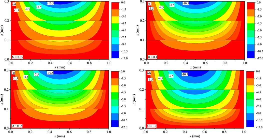
FIGURE 11. Effect of Ω on the heat flux qy (10 W/m2): (A) Ω = 0.05, (B) Ω = 0.1, (C) Ω = 0.15, and (D) Ω = 0.2.
In this part, the solution of the FG QC coating structures with boundary conditions SSSS, CSCS, and CSSS along the thickness direction is presented. The power law index is set as n = 1. The frequency is taken as Ω = 0.1. The horizontal coordinate is fixed at (x, y) = (0.25Lx, 0.75Ly).
Figure 12 illustrates the effects of the different boundary conditions on the phonon and phason displacement components of the coating structures along the thickness direction. It can be observed that the different boundary conditions have an obvious influence on uy, uz, wx, and wy (Figures 12A–D). The maximum magnitudes of uz exist at the top surface of the coating structure. And the values of uz decrease with the increase of clamped-supported boundary conditions. This feature indicates that the clamped-supported boundary conditions have a great effect on uz, and the rigidity of the coating structure is constantly getting stronger.
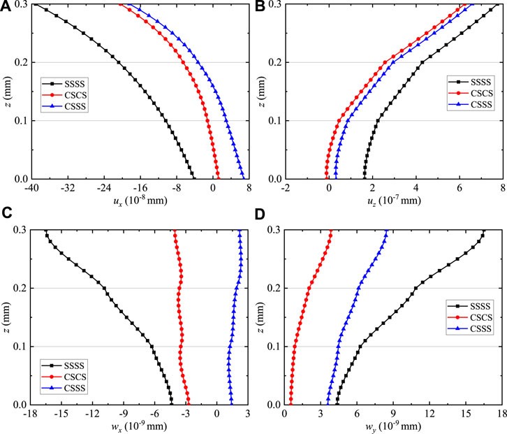
FIGURE 12. Variation of the phonon and phason displacements for QC coating structures: (A) ux, (B) uz, (C) wx, and (D)wy.
Figure 13 illustrates the effects of the different boundary conditions on the phonon and phason stress components of the coating structures along the thickness direction. The distributions of σxz, σzz, σxx, Hxz, Hxx, and Hxy (Figures 13A–F) are considerably altered by the clamped supported boundary conditions. It is noted that the values of σxz, σzz, and Hxz on the bottom and top surfaces are zero (i.e., free tractions for thermal loadings), which validates the present formulation and the numerical results by the surface boundary conditions. The interlaminar stress values of σxx and Hxx with boundary conditions SSSS are greater than that of σxx and Hxx with CSCS and CSSS, while σxy and Hxy are the opposite.
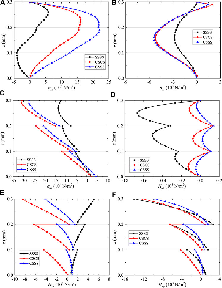
FIGURE 13. Variation of the phonon and phason stresses for QC coating structures: (A) σxz, (B) σzz, (C) σxx, (D) Hxz, (E) Hxx, and (F) Hxy.
Figure 14 illustrates the effects of the different boundary conditions on T and qz of the coating structures along the thickness direction. The values and distributions of T and qz (Figures 14A,B) are insensitive to different boundary conditions, and the heat fluxes qx and qy possess the same feature as qz.
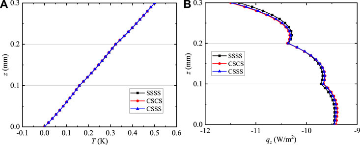
FIGURE 14. Variation of the temperature and heat flux for QC coating structures: (A) T and (B) qz.
The exact solutions for time-harmonic temperature loadings in multilayered anisotropic FG QC coating structures with mixed supported boundary conditions are derived in a thermal environment. While different boundary conditions for each inhomogeneous layer are satisfied using the DQM and the Fourier series to obtain the general field solutions, the multilayered feature is globally handed by improving the traditional propagation matrix method with joint coupling matrices. The present framework admits different mechanical and thermal boundary conditions to derive the exact solutions and can be applied to thick and thin laminated structures, without producing numerical instability issues from high frequency and/or large discrete point numbers. Application illustrations are proposed to throw light on various effects of the power-law index n, frequency Ω, and different boundary conditions on the thermoelastic fields in three multilayered structures, namely:
1) Different from the conventional propagator matrix method, the global propagator relation is reestablished to resolve numerical instabilities in the case of large discrete point numbers and high frequencies for QC coating structures. Numerical examples prove that this method has high precision and good convergence at N = 25.
2) Depending on the input frequency amplitude, severe oscillating displacements and stresses take place on each layer and interface that can endanger the safety-related strength and stiffness of the three-layer coatings. The remarkable change in the magnitude and distributions of the induced thermal stresses σxx, σyy, σxy, Hxx, Hxy, Hyy, Hyx and heat fluxes qx, qy with increasing boundary conditions and frequency amplitude is exhibited.
3) The internal displacement, stress, and temperature fields due to time-harmonically forced vibration for QC coating structures are described using the power law index. The field variables are sensitive to the power law index except for temperature T, and their distributions are different with the change of n.
Overall, the methods and numerical results in this paper can be utilized to validate the accuracy of other numerical methods and serve for the analysis and design of multilayered QC samples with desired time-harmonic thermoelastic responses.
The original contributions presented in the study are included in the article/supplementary material, further inquiries can be directed to the corresponding author.
XF wrote the first draft of the manuscript, and contributed to conception and design of the study. LZ performed the statistical analysis. ZZ and YL processed data and pictures. YG revised manuscript. All authors contributed to manuscript revision, read, and approved the submitted version.
Funding: This work was supported by the National Natural Science Foundation of China (grant numbers 11972365, 12102458, and 12102481) and the China Agricultural University Education Foundation (grant numbers 1101-240001).
The authors declare that the research was conducted in the absence of any commercial or financial relationships that could be construed as a potential conflict of interest.
All claims expressed in this article are solely those of the authors and do not necessarily represent those of their affiliated organizations, or those of the publisher, the editors and the reviewers. Any product that may be evaluated in this article, or claim that may be made by its manufacturer, is not guaranteed or endorsed by the publisher.
The state equations for CSSS are
with
Al-Qahtani, H., and Datta, S. K. (2004). Thermoelastic waves in an anisotropic infinite plate. J. Appl. Phys. 96 (7), 3645–3658. doi:10.1063/1.1776323
Bak, P. (1985). Phenomenological theory of icosahedral incommensurate (quasiperiodic) order in Mn-Al alloys. Phys. Rev. Lett. 54 (14), 1517–1519. doi:10.1103/physrevlett.54.1517
Bak, P. (1985). Symmetry, stability, and elastic properties of icosahedral incommensurate crystals. Phys. Rev. B 32 (9), 5764–5772. doi:10.1103/physrevb.32.5764
Beardsley, M. B. (2008). Potential use of quasicrystalline materials as thermal barrier coatings for diesel engine components[D]. Iowa State University.
Castaings, M., and Hosten, B. (1994). Delta operator technique to improve the Thomson–Haskell‐method stability for propagation in multilayered anisotropic absorbing plates. J. Acoust. Soc. Am. 95 (4), 1931–1941. doi:10.1121/1.408707
Chen, W. Q., Lü, C. F., and Bian, Z. G. (2003). Elasticity solution for free vibration of laminated beams. Compos. Struct. 62 (1), 75–82. doi:10.1016/s0263-8223(03)00086-2
Dolinsek, J. (2012). Electrical and thermal transport properties of icosahedral and decagonal quasicrystals. Chem. Soc. Rev. 41 (20), 6730–6744. doi:10.1039/c2cs35036j
Dunkin, J. W. (1965). Computation of modal solutions in layered, elastic media at high frequencies. Bull. Seismol. Soc. Am. 55 (2), 335–358. doi:10.1785/bssa0550020335
Fan, T. Y. (2011). Mathematical theory of elasticity of quasicrystals and its applications[M]. Heidelberg: Springer.
Guo, J. H., Yu, J., Xing, Y. M., Pan, E., and Li, L. (2016). Thermoelastic analysis of a two-dimensional decagonal quasicrystal with a conductive elliptic hole. Acta Mech. 227 (9), 2595–2607. doi:10.1007/s00707-016-1657-7
Guo, J. H., Zhang, M., Chen, W. Q., and Zhang, X. (2020). Free and forced vibration of layered one-dimensional quasicrystal nanoplates with modified couple-stress effect. Sci. China Phys. Mech. Astron. 63 (7), 274621–274622. doi:10.1007/s11433-020-1547-3
Hu, C. Z., Wang, R. H., and Ding, D. H. (2000). Symmetry groups, physical property tensors, elasticity and dislocations in quasicrystals. Rep. Prog. Phys. 63 (1), 1–39. doi:10.1088/0034-4885/63/1/201
Huang, Y. Z., Li, Y., Yang, L. Z., and Gao, Y. (2019). Static response of functionally graded multilayered one-dimensional hexagonal piezoelectric quasicrystal plates using the state vector approach. J. Zhejiang Univ. Sci. A 20 (2), 133–147. doi:10.1631/jzus.a1800472
Huang, Y. Z., Zhao, M., and Feng, M. L. (2021). Electric–elastic analysis of multilayered two-dimensional decagonal quasicrystal circular plates with simply supported or clamped boundary conditions. Math. Mech. Solids 26 (9), 1337–1353. doi:10.1177/1081286520981618
Li, L. H., and Liu, G. T. (2018). Study on a straight dislocation in an icosahedral quasicrystal with piezoelectric effects. Appl. Math. Mech. 39 (9), 1259–1266. doi:10.1007/s10483-018-2363-9
Li, X. Y., Wang, T., Zheng, R. F., and Kang, G. (2015). Fundamental thermo-electro-elastic solutions for 1D hexagonal QC. Z. Angew. Math. Mech. 95 (5), 457–468. doi:10.1002/zamm.201300095
Li, X. Y. (2013). Fundamental solutions of penny-shaped and half-infinite plane cracks embedded in an infinite space of one-dimensional hexagonal quasi-crystal under thermal loading. Proc. R. Soc. A 469 (2154), 20130023. doi:10.1098/rspa.2013.0023
Li, Y., Yang, L. Z., and Gao, Y. (2018). Thermo-elastic analysis of functionally graded multilayered two-dimensional decagonal quasicrystal plates. Z. Angew. Math. Mech. 98 (9), 1585–1602. doi:10.1002/zamm.201700371
Li, Y., Yang, L. Z., Zhang, L. L., and Gao, Y. (2021). Nonlocal free and forced vibration of multilayered two-dimensional quasicrystal nanoplates. Mech. Adv. Mater. Struct. 28 (12), 1216–1226. doi:10.1080/15376494.2019.1655687
Lü, C. F., Chen, W. Q., and Shao, J. W. (2008). Semi-analytical three-dimensional elasticity solutions for generally laminated composite plates. Eur. J. Mech. - A/Solids 27 (5), 899–917. doi:10.1016/j.euromechsol.2007.12.002
Lü, C., Lee, Y., Lim, C., and Chen, W. (2006). Free vibration of long-span continuous rectangular Kirchhoff plates with internal rigid line supports. J. Sound. Vib. 297 (1-2), 351–364. doi:10.1016/j.jsv.2006.04.007
Maciá, E. (2004). Compatibility factor of segmented thermoelectric generators based on quasicrystalline alloys. Phys. Rev. B 70 (10), 100201. doi:10.1103/physrevb.70.100201
Mal, A. K. (1988). Wave propagation in layered composite laminates under periodic surface loads. Wave motion 10 (3), 257–266. doi:10.1016/0165-2125(88)90022-4
Matsukawa, M., Yoshizawa, M., Noto, K., Yokoyama, Y., and Inoue, A. (1999). Anisotropic thermal transport of 2D quasicrystals of decagonal Al–Ni–Co system. Phys. B Condens. Matter 263 (1-4), 146–148. doi:10.1016/s0921-4526(98)01469-0
Mora, J., García, P., Muelas, R., and Aguero, A. (2020). Hard quasicrystalline coatings deposited by HVOF thermal spray to reduce ice accretion in aero-structures components. Coatings (Basel). 10 (3), 290. doi:10.3390/coatings10030290
Polishchuk, S., Boulet, P., Mézin, A., de Weerd, M. C., Weber, S., Ledieu, J., et al. (2012). Residual stress in as-deposited Al–Cu–Fe–B quasicrystalline thin films. J. Mat. Res. 27 (5), 837–844. doi:10.1557/jmr.2011.415
Saviz, M. R. (2017). Electro-elasto-dynamic analysis of functionally graded cylindrical shell with piezoelectric rings using differential quadrature method. Acta Mech. 228 (5), 1645–1670. doi:10.1007/s00707-016-1746-7
Sun, T. Y., Guo, J. H., and Pan, E. (2021). Nonlocal vibration and buckling of two-dimensional layered quasicrystal nanoplates embedded in an elastic medium. Appl. Math. Mech. 42 (8), 1077–1094. doi:10.1007/s10483-021-2743-6
Tan, E. L. (2006). Hybrid compliance-stiffness matrix method for stable analysis of elastic wave propagation in multilayered anisotropic media. J. Acoust. Soc. Am. 119 (1), 45–53. doi:10.1121/1.2139617
Tan, E. L. (2011). Recursive asymptotic hybrid matrix method for acoustic waves in multilayered piezoelectric media. Open J. Acoust. 1 (2), 27–33. doi:10.4236/oja.2011.12004
Vattré, A., Pan, E., and Chiaruttini, V. (2021). Free vibration of fully coupled thermoelastic multilayered composites with imperfect interfaces. Compos. Struct. 259, 113203. doi:10.1016/j.compstruct.2020.113203
Vattré, A., and Pan, E. (2021). Thermoelasticity of multilayered plates with imperfect interfaces. Int. J. Eng. Sci. 158, 103409. doi:10.1016/j.ijengsci.2020.103409
Yang, L. Z., Li, Y., Gao, Y., and Pan, E. (2018). Three-dimensional exact thermo-elastic analysis of multilayered two-dimensional quasicrystal nanoplates. Appl. Math. Model. 63 (11), 203–218. doi:10.1016/j.apm.2018.06.050
Yang, L. Z., Zhang, L. L., Song, F., and Gao, Y. (2014). General solutions for three-dimensional thermoelasticity of two-dimensional hexagonal quasicrystals and an application. J. Therm. Stresses 37 (3), 363–379. doi:10.1080/01495739.2013.869149
Zhang, L., Guo, J. H., and Xing, Y. M. (2019). Nonlocal analytical solution of functionally graded multilayered one-dimensional hexagonal piezoelectric quasicrystal nanoplates. Acta Mech. 230 (5), 1781–1810. doi:10.1007/s00707-018-2344-7
Keywords: forced vibration analysis, quasicrystal coating structures, functionally graded materials, mixed boundary conditions, thermoelastic analysis
Citation: Feng X, Zhang L, Zhu Z, Li Y and Gao Y (2022) Forced vibration analysis of inhomogeneous quasicrystal coating in a thermal environment. Front. Mater. 9:963149. doi: 10.3389/fmats.2022.963149
Received: 07 June 2022; Accepted: 18 July 2022;
Published: 26 September 2022.
Edited by:
Chunli Zhang, Zhejiang University, ChinaReviewed by:
Xiangyu Li, Southwest Jiaotong University, ChinaCopyright © 2022 Feng, Zhang, Zhu, Li and Gao. This is an open-access article distributed under the terms of the Creative Commons Attribution License (CC BY). The use, distribution or reproduction in other forums is permitted, provided the original author(s) and the copyright owner(s) are credited and that the original publication in this journal is cited, in accordance with accepted academic practice. No use, distribution or reproduction is permitted which does not comply with these terms.
*Correspondence: Yang Gao, Z2FveWFuZ2dAZ21haWwuY29t
Disclaimer: All claims expressed in this article are solely those of the authors and do not necessarily represent those of their affiliated organizations, or those of the publisher, the editors and the reviewers. Any product that may be evaluated in this article or claim that may be made by its manufacturer is not guaranteed or endorsed by the publisher.
Research integrity at Frontiers
Learn more about the work of our research integrity team to safeguard the quality of each article we publish.