 Shuangshuang Chang
 Yanhong Jia2†
 Xin Du
 Shaoqiang Guo
- 1School of Nuclear Science and Technology, Xi’an Jiaotong University, Xi’an, China
- 2China Institute of Atomic Energy, Beijing, China
Pyroprocessing of spent nuclear fuels uses the LiCl–KCl molten salt as an electrolyte, which contains dissolved fission products and can be very corrosive to the structural alloys. This study investigates the effect of EuCl3 on the corrosion behavior of four commercial alloys: Haynes C276, Inconel 600, Incoloy 800, and 316L stainless steel. Static immersion tests and electrochemical polarization measurements were carried out in molten LiCl–KCl salts with and without EuCl3 additives at 500°C. The results showed that the presence of EuCl3 caused the severe dissolution of Ni, Fe, and Cr from alloys, accompanied by the cathodic reduction of EuCl3 to EuCl2. All alloys suffered from intergranular dissolution and cracking, with additional pitting and void attacks for Incoloy 800 and 316L stainless steel.
1 Introduction
Nuclear energy produces carbon-free electricity and plays an important role in reducing the carbon emissions. However, for the sustainable development of nuclear energy, the spent nuclear fuels (SNFs) must be reprocessed to recycle the fertile and fissile materials (e.g., uranium) and to minimize the radioactive nuclear waste. Pyroprocessing is a next-generation SNF reprocessing technology based on molten salt electrolysis. Compared to the conventional hydrometallurgy process, pyroprocessing exhibits some usual benefits, including high resistance to radiation, less proliferation risk, minimum radioactive waste, and low criticality safety risk (IAEA, 2008).
The electrorefining of uranium in LiCl–KCl molten salt is the key step of pyroprocessing. As the formation of the protective oxide layer on the alloy surface is challenged in molten chloride media, the structural alloys used for the construction of an electrorefiner may suffer corrosion attack during its design life (e.g., 40 years). To screen the candidate alloys, several studies have evaluated the corrosion resistance of commercial alloys in LiCl–KCl molten salt (Shankar et al., 2010; Shankar et al., 2013a; Shankar et al., 2013b; Rao et al., 2015). In general, alloys exhibit preferential dissolution or oxidation of the active element Cr, which is induced by impurities such as moisture and oxygen in the molten salt. The weight loss for all alloys tested under an inert atmosphere is insignificant. However, it should be noticed that a high concentration of actinide and fission products (e.g., Cs, Sr, and lanthanides) are dissolved as their chloride products in LiCl–KCl molten salt during electrorefining. UCl3 was found to have an activating effect on the corrosion, especially the localized corrosion, at grain boundaries of EP-823 steel in molten LiCl–KCl salt, while CeCl3 and NdCl3 showed a weak inhibitory effect (Nikitina et al., 2019). However, there is also a study that observed little corrosion for alloys exposed to LiCl–KCl–UCl3 molten salt (Rao et al., 2018). The soluble fission product Cs may induce severe intergranular cracking and void attacks, as observed for stainless steels and a single-crystal superalloy in LiCl–KCl–CsCl molten salt (Hofmeister et al., 2015). The addition of LaCl3 decelerates the corrosion rate of pure nickel because of the formation of a protective LaOCl film (Karfidov and Nikitina, 2019). In our previous study (Guo et al., 2020), EuCl3 was revealed to be very oxidizing in LiCl–KCl molten salt, which caused the rapid dissolution of Inconel 718 and Alloy 709 with additional intergranular cracking in Inconel 718. In theory, chlorides of uranium and fission products may influence the alloy corrosion by oxidation or chlorination of the oxide layer. This may be illustrated using electrochemical characterization and a thermodynamical phase diagram, which has not been visited. Therefore, this study further investigated the effect of EuCl3 on the corrosion behaviors of four commercial alloys in LiCl–KCl molten salt using the E-pO2− diagram, electrochemical polarization, and immersion tests.
2 Materials and Methods
Haynes C276, Inconel 600, Incoloy 800, and SS 316L were tested in this study. The chemical compositions of the four commercial alloys are shown in Table 1. Alloy coupons with a dimension of 15 mm
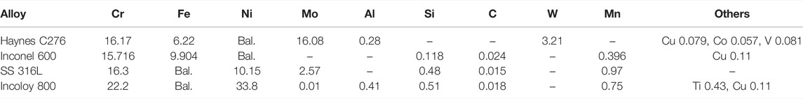
TABLE 1. Chemical compositions of the alloys (wt%).
All tests and salt preparations were conducted in an argon-filled glove box (Mikrouna Universal) in which the concentrations of moisture and oxygen contaminations in the Ar atmosphere were controlled less than 0.01 and 1 ppm, respectively. All salt constituents were procured from Aladdin with purity of 99% for LiCl, 99.99% for KCl, and 99.9% for EuCl3. For each test, approximately 70 g of LiCl–KCl eutectic with desired EuCl3 concentration was weighed using an analytical balance (Mettler, 10−4 g accuracy) and then mixed in an alumina crucible. The crucible was put into a muffle furnace equipped with three-electrode assembly on the lid. Prior to testing, the salt was dehydrated at 200°C for 1 h to minimize the O2− byproduct that may result from dehydration at evaluated temperatures. A test temperature of 500°C was selected, which is the typical operating temperature in the spent fuel electrorefiner. No HCl or CCl4 gas sparging was performed to further remove the possible O2− impurities in the melt.
Once the salt was melted at 500°C, alloy samples attached with nickel wires were lowered into the salt solution. The duration for the immersion test was 24 h. After the test, alloy samples were naturally cooled to room temperature, and the residual salt on the coupon surface was cleaned with deionized water and ethanol. The corrosion morphologies and chemical compositions of the corroded samples were characterized using scanning electron microscopy (SEM, Zeiss GeminiSEM 500) equipped with energy dispersive spectroscopy (EDS, Oxford Ultim Max 50).
Electrochemical measurements were carried out using a Gamry Interface 1010E potentiostat. The electrodes were isolated using quartz tubes and inserted through electrode holes customized on the furnace lid. The counter electrode is a 3-mm-diameter graphite rod. The Ag/AgCl reference electrode was made by dipping a 0.5-mm-diameter silver wire in the LiCl−KCl eutectic salt with addition of 1 wt% AgCl. The reference salt was contained in a 5-mm NMR tube. In this paper, all electrode potential values are reported versus the Ag/AgCl reference electrode unless otherwise specified. Alloy samples were used as the working electrode for the polarization measurement. The potentiodynamic scan was performed after the stabilization of the open circuit potential (OCP), which typically took less than 1 h. The potential was swept from −0.15 to +0.5 V versus the OCP at a scan rate of 0.167 mV/s. Cyclic voltammetry (CV) was also carried out using a 1-mm-diameter tungsten rod as the working electrode to monitor the evolution of soluble ionic corrosion products in the molten salt at a scan rate of 100 mV/s.
3 Results
3.1 Thermodynamics and Corrosion Kinetics
Owing to the hydrophilic nature of chloride salt, moisture is the most common contaminant that will react with chlorine ions to form oxide ions according to
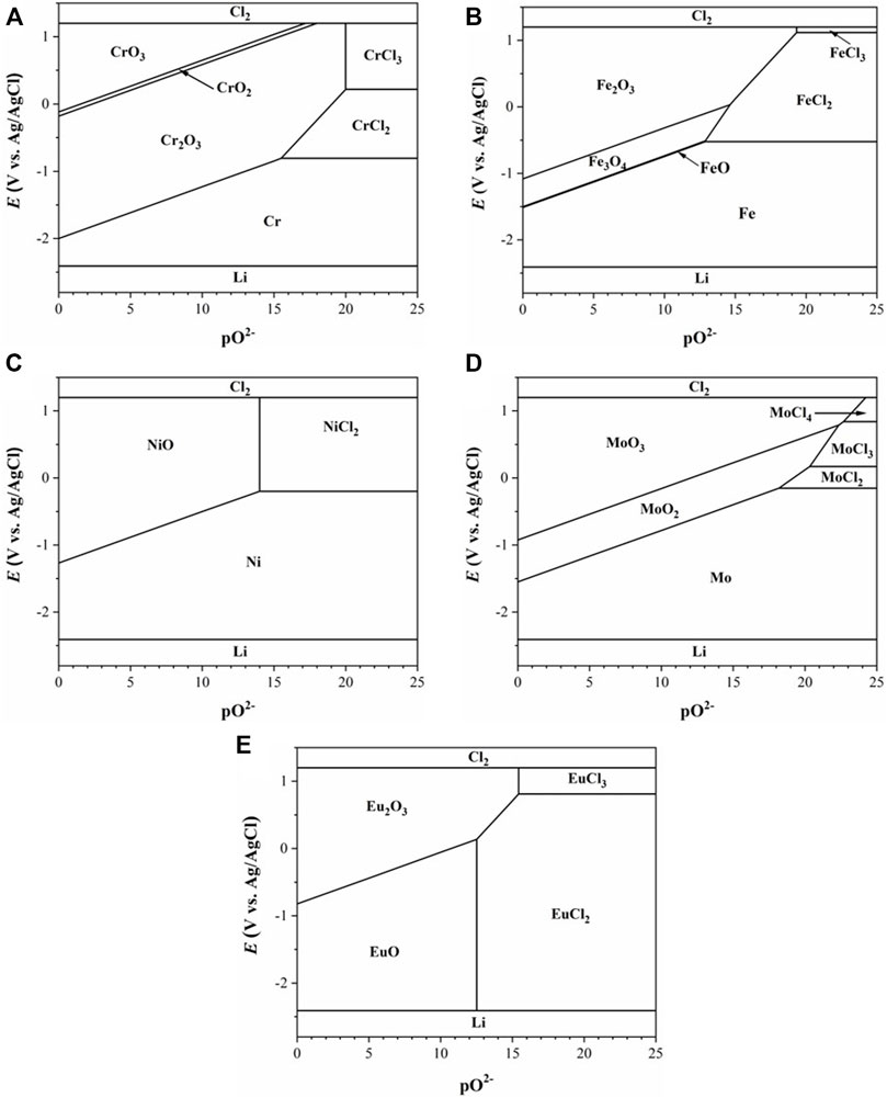
FIGURE 1. E-pO2− diagrams calculated at 500°C for Cr (A), Fe (B), Ni (C), Mo (D), and Eu (E) in LiCl–KCl.
To identify the corrosion kinetics of Haynes C276, Inconel 600, SS 316L, and Incoloy 800, potentiodynamic scan was conducted with a scan rate of 0.167 mV/s in the anodic direction. As shown in Figure 2A, all four alloys exhibit active dissolution at their natural corrosion potentials. The corrosion potentials are all located near the chlorination potential of Fe. This suggests the dissolution of Cr from Incoloy 800 and additional dissolution of Fe for other three alloys at the corrosion potential. It is also noticed that the anodic dissolution rates of Haynes C276 and Inconel 600 are considerably lower than those of SS 316L and Incoloy 800. This should be attributed to the lower Cr and Fe content in nickel alloys of Haynes C276 and Inconel 600. The anodic passivation was observed in the potential range starting from approximately −0.5 V, where formation of oxides of Cr, Fe, and Mo are possible. With the increase of potential, all alloys suffered from transpassive dissolution above −0.2 V that corresponds to the chlorination potential of Ni. In comparison, the changes of cathodic current near the OCP is more enhanced, following an order of Haynes C276 > Inconel 600 = SS 316L > Incoloy 800. This is in the same trend with the changes in the corrosion potential. It is clear that the increase in the cathodic reaction rate is responsible for the increase in the corrosion potential, considering that it takes away excess electrons with negative charges from the alloy surface. The cathodic reaction should be contributed to the impurities in the salt such as moisture, oxygen, and metallic impurities. Because all alloy specimens are tested in the same salt under a well-controlled atmosphere, the increase in the cathodic reaction rate may indicate a decrease in the work function of the alloy, which defines the energy for losing an electron from the alloy matrix.
FIGURE 2. Polarization curves of alloys obtained in the molten salt at 500°C: (A) LiCl–KCl; (B) LiCl–KCl–2 wt% EuCl3; (C) SS 316L in LiCl–KCl–EuCl3; and (D) the corrosion rates calculated from the corrosion current densities in (A), (B), and (C).
Figure 2B shows the polarization curves of the four alloys obtained in the LiCl–KCl–2 wt% EuCl3. Compared to the blank LiCl–KCl salt, the cathodic current is increased by approximately two orders of magnitude because of the presence of oxidizing EuCl3. The corrosion potentials of all alloys are thus increased to values of above −0.2 V, which corresponds to the chlorination potential of nickel. At these potentials, the alloys undergo transpassive dissolution, as we previously observed in Figure 2A. It is reasonable to infer that all alloy elements including noble nickel are actively dissolved in the presence of EuCl3. The reduction of EuCl3 to EuCl2 should be responsible for the cathodic reaction. The feature of the limiting diffusion current observed in the cathodic polarization curves indicates that the reduction rate of EuCl3 is very fast and limited by the diffusion rate of Eu(III) ions from the bulk solution to the metal surface. Increase in the EuCl3 concentration results in the increase in the cathodic limiting current density, as shown in Figure 2C. It should be mentioned that the increment of the limiting current is not proportional to the increase in the nominal concentration of EuCl3 as suggested by Eq. 1. This is probably because of the thermal decomposition of EuCl3 to EuCl2, i.e.,
where
The corrosion current density was determined by the extrapolation of the cathodic polarization curve at the corrosion potential. For the case of EuCl3, the corrosion current equals the cathodic limiting current. The rate of alloy corrosion
where
The corrosion products dissolved in the molten salt after the polarization tests were monitored using CV measurement. As shown in Figure 3, three pairs of redox peaks are observed from the cyclic voltammograms recorded in LiCl–KCl–2 wt% EuCl3 melt. The cathodic peak centered at 0.17 V corresponds to the reduction of EuCl3, which is a one-electron exchange process with the formation of soluble EuCl2 (Kim et al., 2011). Another two pairs of redox peaks are clearly observed with onset potentials of −0.13 and −0.47 V. According to reported formation potential values in the literature (Guo et al., 2018), these two peaks are associated with the redox behaviors of soluble Ni(II) and Fe(II) ions in the molten salt. Hence, it is evident that considerable amounts of nickel and iron from the alloy specimens were chlorinated by EuCl3 during the anodic polarization. There are no soluble Cr and Mo ions detected from the CV signals. This might be because of the formation of chromium and molybdenum oxides, which can be formed at relatively lower O2− concentrations than those of Ni and Fe (see Figure 1). Nevertheless, the formed oxides must be nonprotective and might be destabilized from the alloy surface. Accumulation of black oxide powders had been previously observed after the corrosion of Alloy 709 and Inconel 719 in LiCl–KCl–EuCl3 melt (Guo et al., 2020).
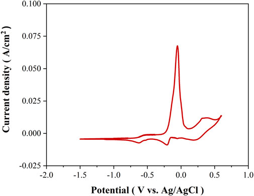
FIGURE 3. Cyclic voltammetry curves recorded on tungsten WE after the polarization tests in LiCl–KCl–2 wt% EuCl3 molten salt.
3.2 Scanning Electron Microscopy Corrosion Morphologies
To identify the influence of EuCl3 on the corrosion morphologies, corrosion tests were carried out in LiCl–KCl and LiCl–KCl–2 wt% EuCl3 molten salts at 500°C. Considering the fast dissolution rate of alloys in the presence of EuCl3, the test duration must be limited to prevent the premature running out of the EuCl3 in the salt solution. Once all EuCl3 has been consumed, reduction of the soluble nickel corrosion product will be involved in the corrosion process. This results in the formation of a metallic nickel layer on the alloy surface, making it unsuitable for the observation of the europium-induced corrosion attack (Guo et al., 2020). In theory, a reduction of 2 wt% EuCl3 in 70-g LiCl–KCl salt mixture will chlorinate approximately 0.15 g of Fe, which corresponds to 170-µm corrosion depth for each side of the tested alloy specimen. According to the corrosion rates determined from the polarization curves in Figure 3D, the calculated corrosion depths are 91 ± 5 µm after 24 h of immersion. Therefore, the test duration of 24 h is good to observe the corrosion attack induced by EuCl3 and to avoid the depletion of EuCl3.
3.2.1 Haynes C276
Figure 4 shows the SEM images of Haynes C276 alloy specimens after 24 h of immersion in LiCl–KCl and LiCl–KCl–2 wt% EuCl3 molten salts. After immersion in LiCl–KCl salt, the alloy surface is quite flat without formation of any corrosion product. The fluctuation of the surface is much less than the corrosion depth calculated from the corrosion rate in Figure 2D, which is 0.95 µm after 24 h of immersion. Hence, it can be deduced that Haynes C276 suffered uniform corrosion at very limited rate in the blank LiCl–KCl salt. However, after the addition of 2 wt% EuCl3 in the initial salt, severe intergranular corrosion attack with an average depth of approximately 29 µm was observed (see Figures 4C,D). As the grain boundary is a rapid diffusion channel for alloy elements, the intergranular dissolution is a common feature in molten halide salts where formation of a protective oxide layer is not favorable (Fabre et al., 2013; McAlpine et al., 2020). This is more pronounced in this case because the alloy dissolution rate is significantly enhanced by the oxidizing EuCl3. EDS mapping of the cross-sectional images demonstrated that elements of Ni, Fe, and Cr are dissolved, while Mo seems only partially dissolved and segregates near the grain boundaries. This might be because of the relatively positive chlorination potential of Mo and possible formation of MoO2 at lower O2− concentrations (see Figure 1).
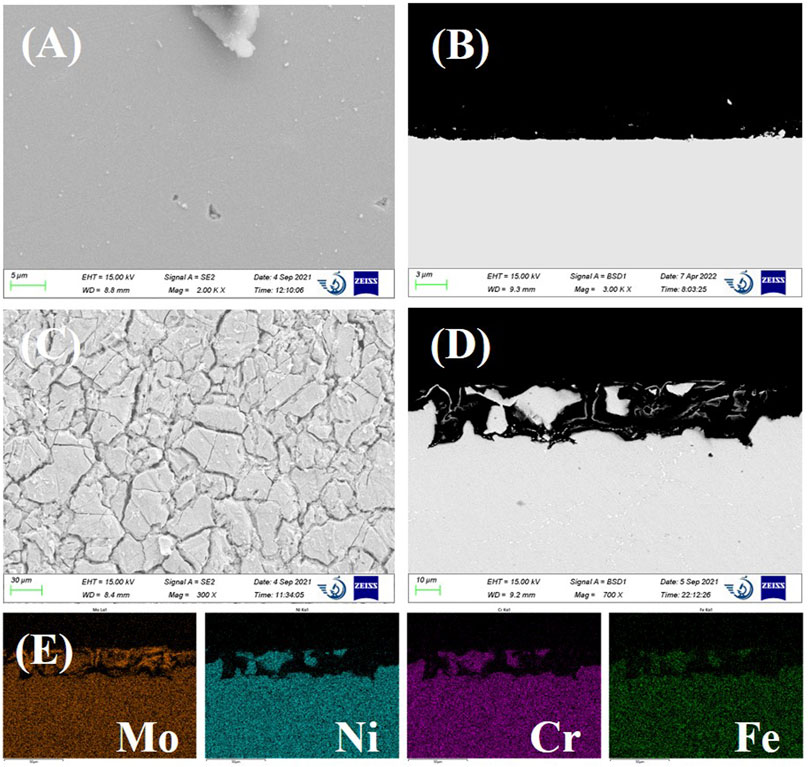
FIGURE 4. (A) scanning electron microscopy (SEM) surface image and (B) cross-sectional backscattered electron SEM image of Haynes C276 after 24-h immersion in LiCl–KCl. (C) SEM surface image and (D) cross-sectional image of Haynes C276 after 24-h immersion in LiCl–KCl–2 wt% EuCl3. (E) energy dispersive spectroscopy (EDS) mapping results of SEM image (D).
3.2.2 Inconel 600
For Inconel 600, no obvious corrosion except some nickel-rich particles were observed from the SEM surface image (see Figure 5A). As suggested from the shape of the particle locations, these Ni-rich particles might be the intergranular precipitates that resulted from the selective dissolution of Cr at the grain boundaries. The cross-sectional image shows some surface roughness. In comparison, the presence of 2 wt% EuCl3 in the melt largely accelerated the alloy corrosion. As shown in Figures 5C,D, significant intergranular corrosion with some well-developed intergranular cracks up to a depth of 60 µm was clearly observed. The EDS mapping of the cross-sectional images was checked, which showed a uniform distribution of elements Ni, Fe, and Cr in the alloy matrix. This means that all alloy elements are dissolved at a similar rate because of the addition of EuCl3. In addition, oxygen was not detected at the alloy interface from the EDS analysis results.
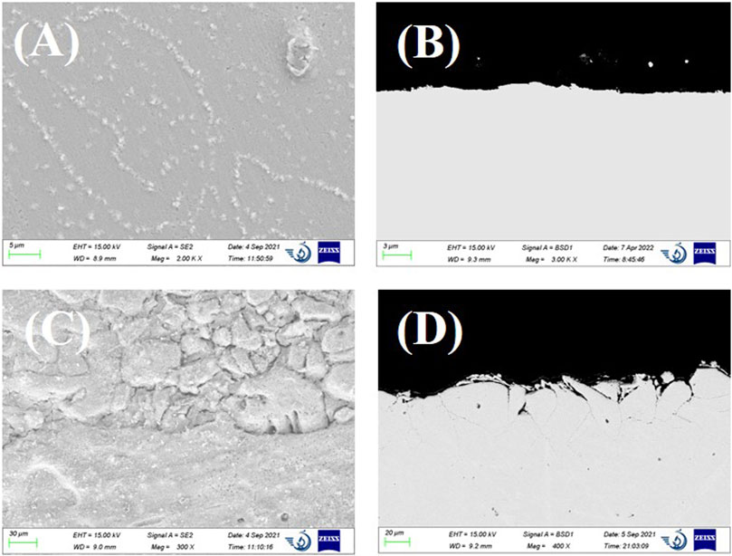
FIGURE 5. (A) SEM surface image and (B) cross-sectional backscattered electron SEM image of Inconel 600 after 24-h immersion in LiCl–KCl. (C) SEM surface image and (D), cross-sectional image of Inconel 600 after 24 h immersion in LiCl–KCl–2 wt% EuCl3.
3.2.3 Incoloy 800
As can be seen from Figures 6A,B, the immersion of Incoloy 800 in LiCl–KCl molten salt only results in slight surface roughening. The EDS mapping of the cross-sectional image found no obvious Cr depletion in the near-surface region, which might be because of the very low dissolution rate. After the addition of 2 wt% EuCl3, Incoloy 800 suffered from severe intergranular corrosion up to a depth of 65 µm. Dense cracks were clearly observed at the grain boundaries. There are also some voids distributed in the near-surface corroded region, which should be because of the depletion of alloy elements. Although the polarization curves indicated the lowest general dissolution rate of Incoloy 800, the intergranular corrosion and void attack are more severe than those of Inconel 600.
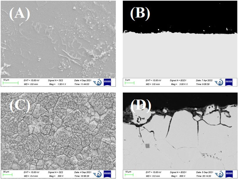
FIGURE 6. (A) SEM surface image and (B) cross-sectional backscattered electron SEM image of Incoloy 800 after 24-h immersion in LiCl–KCl. (C) SEM surface image and (D) cross-sectional image of Incoloy 800 after 24-h immersion in LiCl–KCl–2 wt% EuCl3.
3.2.4 SS 316L
SS 316L exhibits corrosion features similar to those of Incoloy 800. Little corrosion attack was observed on SS 316L immersed in LiCl–KCl molten salt. After the addition of EuCl3, SS 316L suffered from severe intergranular attack and additional pitting corrosion. With the rapid dissolution of alloy elements at the grain boundaries, the cracks were formed and propagated deeply along the grain boundaries up to a depth of 42 µm. Many voids were observed near the grain boundaries region, which is a clear sign of diffusion of alloy elements from the grain matrix to the gran boundaries. Therefore, it can be deduced that the intergranular cracks were formed by the enhanced anodic dissolution mechanism at the grain boundaries. In addition, the size of the pits seems closely related to the grain size, ranging from several to hundreds of micrometers. As shown in Figure 7D, some grains at the surface were totally isolated from the alloy matrix by the intergranular cracks. In due course, the isolated grain may be peeled off from the bulk alloy, resulting in the formation of surface pitting.
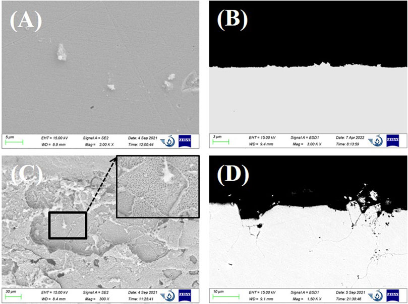
FIGURE 7. (A) SEM surface image and (B) cross-sectional backscattered electron SEM image of SS 316L after 24-h immersion in LiCl–KCl. (C) SEM surface image and (D) cross-sectional image of SS 316L after 24-h immersion in LiCl–KCl–2 wt% EuCl3.
According to above observations, Haynes C276, Inconel 600, Incoloy 800, and SS 316L all exhibit rapid dissolution of elements of Ni, Fe, and Cr because of the presence of EuCl3 in the salt. The polarization results indicated a general dissolution rate of 19.00∼31.26 mm/a at a 2 wt% EuCl3 concentration. Such a high dissolution rate leads to severe localized attacks including intergranular corrosion cracks, voids, and pitting corrosion. Therefore, the fission product europium is a threat to the construction of the spent fuel electrorefiner using these commercial alloys. During the electrorefining of the spent nuclear fuel, lanthanides as a main group of fission products was dissolved in the LiCl–KCl electrolyte salt. The concentration of the soluble europium product depends on the burn-up of the spent fuel and the reprocessing time. Let us take the EBR-II spent metallic fuel as an example. An accumulation rate of approximately 3 wt% lanthanide fission products in the salt electrolyte per ton of processed uranium was found during the treatment (Bae et al., 2010). Although the contribution of europium to the lanthanide fission product group is typically only approximately 1–2 wt%, its concentration will increase with the processing time. Hence, the concentration of EuCl3 must be controlled below a limiting value where the corrosion rate satisfies the design life of the electrorefiner (e.g., 40 years). This may be achieved by periodic replacement of the electrolyte salt or by removal of the europium products using separation techniques such as electrochemical deposition. It should also be acknowledged that the presence of other fission products may mitigate the europium-accelerated corrosion, as recently observed in LiF–NaF–KF molten salt (McAlpine et al., 2020). The reason might be the complex salt redox conditions involving other fission products that may neutralize some portions of Eu(III) to nonoxidizing Eu(II). It is also worthy to notice that the corrosion rate is also influenced by the addition of UCl3, CeCl3, and NdCl3 in LiCl–KCl molten salt (Nikitina et al., 2019). Therefore, further experimental investigations in the simulated electrolyte salt including UCl3 and miscellaneous soluble fission products at various concentrations are necessary.
4 Conclusion
In the present study, the corrosion of Haynes C276, Inconel 600, Incoloy 800, and SS 316L were carried out in molten LiCl–KCl and LiCl–KCl–EuCl3 salt at 500°C under an argon atmosphere. The corrosion of all alloys in molten LiCl–KCl salt is mainly the selective dissolution of Cr and Fe elements at a relatively slow rate (less than 0.3 mm/a). However, with the presence of EuCl3, all alloys suffered from the rapid dissolution of elements of Ni, Fe, and Cr. The anodic dissolution of elements results in the severe intergranular corrosion and cracking of all tested alloys and additional pitting and void attacks of Incoloy 800 and SS 316L. The dissolution rates are controlled by the mass transfer rate of Eu(III) ions from the bulk solution to the alloy surface. In molten salt containing 2 wt% EuCl3, the corrosion rates of the alloys are in the range of 19.0∼31.3 mm/a, which are two orders of magnitude higher than that in the blank LiCl–KCl salt. Periodical lowering of the concentration of EuCl3 in the electrolyte salt may be a way to mitigate the alloy dissolution induced by EuCl3, which might be achieved by electrochemical deposition or addition of reducing agents such as lithium.
Data Availability Statement
The raw data supporting the conclusions of this article will be made available by the authors, without undue reservation.
Author Contributions
SC: experiment, investigation, writing—original draft. YJ: investigation, funding acquisition, writing—review and editing. XD: investigation, formal analysis. SG: conceptualization, methodology, writing—original draft, writing—review and editing, funding acquisition, supervision.
Funding
This study was funded by the Natural Science Basic Research Program of Shaanxi Province (Program No. 2022JQ-372).
Conflict of Interest
The authors declare that the research was conducted in the absence of any commercial or financial relationships that could be construed as a potential conflict of interest.
Publisher’s Note
All claims expressed in this article are solely those of the authors and do not necessarily represent those of their affiliated organizations, or those of the publisher, the editors, and the reviewers. Any product that may be evaluated in this article, or claim that may be made by its manufacturer, is not guaranteed or endorsed by the publisher.
Acknowledgments
The authors wish to thank Zijun Ren at Instrument Analysis Center of Xi’an Jiaotong University for his assistance with SEM analysis. In addition, special thanks go to Jiong Qian at Jiuli Hi-Tech Metals for providing the Haynes C276, Inconel 600, Incoloy 800, and SS 316L alloy bars.
References
Bae, S.-E., Park, Y. J., Min, S. K., Cho, Y. H., and Song, K. (2010). Aluminum Assisted Electrodeposition of Europium in LiCl-KCl Molten Salt. Electrochimica Acta 55 (8), 3022–3025. doi:10.1016/j.electacta.2009.12.075
De Córdoba, G., and Caravaca, C. (2006). Potentiometric Study of Sm-O Compounds Formation in the Molten LiCl-KCl Eutectic at 450°C. Determination of a E-pO2− Stability Diagram. J. Phys. Chem. Solids 67 (8), 1862–1868. doi:10.1016/j.jpcs.2006.04.011
Fabre, S., Cabet, C., Cassayre, L., Chamelot, P., Delepech, S., Finne, J., et al. (2013). Use of Electrochemical Techniques to Study the Corrosion of Metals in Model Fluoride Melts. J. Nucl. Mater. 441 (1-3), 583–591. doi:10.1016/j.jnucmat.2013.03.055
Fusselman, S. P., Roy, J. J., and Grimmett, S. L. (1999). Thermodynamic Properties for Rare Earths and Americium in Pyropartitioning Process Solvents. J J. Electrochem. Soc. 146 (7), 2573–2580.
Guo, S., Zhang, J., Wu, W., and Zhou, W. (2018). Corrosion in the Molten Fluoride and Chloride Salts and Materials Development for Nuclear Applications. Prog. Mater. Sci. 97, 448–487. doi:10.1016/j.pmatsci.2018.05.003
Guo, S., Zhuo, W., Wang, Y., and Zhang, J. (2020). Europium Induced Alloy Corrosion and Cracking in Molten Chloride Media for Nuclear Applications. Corros. Sci. 163, 108279. doi:10.1016/j.corsci.2019.108279
Hofmeister, M., Klein, L., Miran, H., Rettig, R., Virtanen, S., and Singer, R. F. (2015). Corrosion Behaviour of Stainless Steels and a Single Crystal Superalloy in a Ternary LiCl-KCl-CsCl Molten Salt. Corros. Sci. 90, 46–53. doi:10.1016/j.corsci.2014.09.009
IAEA (2008). Spent Fuel Reprocessing Options. Vienna, Austria: International Atomic Energy Agency, IAEA-TECDOC-1587.
Karfidov, E. A., and Nikitina, E. V. (2019). Corrosion Electrochemical Behavior of Nickel in the LiCl-KCl Melt Containing Lanthanum Trichloride. Russ. Metall. 2019 (8), 820–824. doi:10.1134/s003602951908007x
Kim, T.-J., Uehara, A., Nagai, T., Fujii, T., and Yamana, H. (2011). Quantitative Analysis of Eu2+ and Eu3+ in LiCl-KCl Eutectic Melt by Spectrophotometry and Electrochemistry. J. Nucl. Mater. 409 (3), 188–193. doi:10.1016/j.jnucmat.2010.12.004
Kuznetsov, S. A., and Gaune-Escard, M. (2001). Redox Electrochemistry and Formal Standard Redox Potentials of the Eu(III)/Eu(II) Redox Couple in an Equimolar Mixture of Molten NaCl. Electrochimica. Acta 46, 1101–1111. doi:10.1016/s0013-4686(00)00708-8
Kuznetsov, S. A., Rycerz, L., and Gaune-Escard, M. (2005). Electrochemical and Calorimetric Investigations of Some Thermodynamic Properties of EuCl3 and EuCl2 Dissolved in Alkali Chloride Melts. J. Nucl. Mater. 344 (1-3), 152–157. doi:10.1016/j.jnucmat.2005.04.034
Laitinen, H. A., and Liu, C. H. (1958). An Electromotive Force Series in Molten Lithium Chloride-Potassium Chloride Eutectic1. J. Am. Chem. Soc. 80, 1015–1020. doi:10.1021/ja01538a001
McAlpine, S. W., Skowronski, N. C., Zhou, W., Zheng, G., and Short, M. P. (2020). Corrosion of Commercial Alloys in FLiNaK Molten Salt Containing EuF3 and Simulant Fission Product Additives. J. Nucl. Mater. 532, 151994. doi:10.1016/j.jnucmat.2020.151994
Nikitina, E. V., Kazakovtseva, N. A., and Karfidov, E. A. (2019). Corrosion of 16Cr12MoWSVNbB (EP-823) Steel in the LiСl-KCl Melt Containing CeCl3, NdCl3 and UCl3. J. Alloys Compd. 811, 152032. doi:10.1016/j.jallcom.2019.152032
Rao, C. J., Ningshen, S., Mallika, C., and Mudali, U. K. (2018). Molten Salt Corrosion Behavior of Structural Materials in LiCl-KCl-UCl3 by Thermogravimetric Study. J. Nucl. Mater. 501, 189–199. doi:10.1016/j.jnucmat.2018.01.012
Rao, C. J., Shankar, A. R., Ajikumar, P. K., Kamruddin, M., Mallika, C., and Mudali, U. K. (2015). Corrosion Behavior of Structural Materials in LiCl-KCl Molten Salt by Thermogravimetric Study. Corrosion 71, 502–509. doi:10.5006/1341
Ravi Shankar, A., Mathiya, S., Thyagarajan, K., and Kamachi Mudali, U. (2010). Corrosion and Microstructure Correlation in Molten LiCl-KCl Medium. Metall Mat Trans A 41 (7), 1815–1825. doi:10.1007/s11661-010-0223-5
Shankar, A. R., Kanagasundar, A., and Mudali, U. K. (2013a). Corrosion of Nickel-Containing Alloys in Molten LiCl-KCl Medium. Corrosion 69, 48–57. doi:10.5006/0627
Shankar, A. R., Thyagarajan, K., and Mudali, U. K. (2013b). Corrosion Behavior of Candidate Materials in Molten LiCl-KCl Salt under Argon Atmosphere. Corrosion 69, 655–665. doi:10.5006/0746
Keywords: molten salt corrosion, europium, LiCl–KCl, Haynes C276, Inconel 600, Incoloy 800, 316L stainless steel
Citation: Chang S, Jia Y, Du X and Guo S (2022) Corrosion Behavior of Commercial Alloys in LiCl–KCl Molten Salt Containing EuCl3. Front. Mater. 9:958296. doi: 10.3389/fmats.2022.958296
Received: 31 May 2022; Accepted: 13 June 2022;
Published: 22 July 2022.
Edited by:
Yi Xu, Nanchang University, ChinaReviewed by:
Xiankang Zhong, Southwest Petroleum University, ChinaHongchi Ma, University of Science and Technology Beijing, China
Copyright © 2022 Chang, Jia, Du and Guo. This is an open-access article distributed under the terms of the Creative Commons Attribution License (CC BY). The use, distribution or reproduction in other forums is permitted, provided the original author(s) and the copyright owner(s) are credited and that the original publication in this journal is cited, in accordance with accepted academic practice. No use, distribution or reproduction is permitted which does not comply with these terms.
*Correspondence: Shaoqiang Guo, Z3VvczIwMTlAbWFpbC54anR1LmVkdS5jbg==
†These authors share first authorship