 Tianhua Meng
 Guozhong Zhao2*
95% of researchers rate our articles as excellent or good
Learn more about the work of our research integrity team to safeguard the quality of each article we publish.
Find out more
ORIGINAL RESEARCH article
Front. Mater. , 30 August 2022
Sec. Thin Solid Films
Volume 9 - 2022 | https://doi.org/10.3389/fmats.2022.957909
Aiming at the difficulty of accurately calibrating the sample position in the terahertz (THz) imaging process, especially in the defect imaging detection and the precise characterization of the edge profile, a flexible and highly sensitive 3D terahertz displacement sensor with a resolution of up to 1 μm was proposed by the artificial electromagnetic metamaterials. The high resolution of the flexible sensor can be attributed to the used artificial electromagnetic metamaterials with the enhancing sensitivity of THz sensors as well as the flexible substrate with the high fitting to the target. Unlike the laser displacement sensor with a complex and large volume of the generating device, the proposed flexible sensor with a simple structural design is composed of only a fixed layer and a displacement indicating layer. The fixed layer is composed of the Mylar flexible substrate layer and the metal split resonator ring on it, and the displacement indicating layer is composed of the Mylar flexible substrate layer and the metal indicator lines on it. By using this unique double-layer structure, high-sensitivity measurement of displacement can be achieved by measuring the moving amount of the metal indicator line corresponding to the valley change in the THz transmission of the displacement sensor. The results demonstrate that the sensitivity of the displacement sensor can reach 145 GHz/μm, the quality factor Q can reach 194.67, and the quality factor figure of merit can reach 6.25 μm−1. Compared with the mature commercial displacement sensors and laser displacement sensors, the proposed sensor can have the characteristics of compact structure, simple preparation process, high-sensitivity, and flexibility, which can offer certain advantages for the realization of high-precision, miniaturization, and distributed sensing systems in the future.
Terahertz (THz) wave occupies a very special position in the electromagnetic spectrum, and its frequency band is in a special region of transition from electronics to photonics. The special frequency position not only makes THz waves have low-frequency microwave characteristics and photonics characteristics but also exhibits unique properties such as low photon energy, strong penetration of nonmetallic and nonpolar substances, simultaneous acquisition of the information of the pulsed electric field amplitude and phase, and good anti-interference ability (Sirtori, 2002; Lee, 2009). It can have broad application prospects in the fields of security detection, nondestructive detection, spectral analysis, imaging, medical treatment, etc., especially the urgent application requirements of high-performance THz imaging technology. However, in the current imaging system with submicron accuracy, the inevitable negative defects of coherent fringe and laser speckle have greatly limited the further development of this technology. On the hardware side, large-area, uniform, and intensity-controllable THz radiation sources; high-sensitivity THz detection devices; and the limitation of high thermal radiation background noise in the THz frequency band are lacking (Mittleman, 2018; Zanotto et al., 2020; Bandyopadhyay and Sengupta, 2021). As for the THz image processing software, the THz image can have inevitable edge loss, smearing, and ghosting because of the use of conventional technology, such as calibration-based nonuniformity correction, scene-based nonuniformity correction, image preprocessing, and fusion technology (Stark, 2000; Recur et al., 2011). In the past decade, the improving resolution of the THz imaging system has been studied using various approaches. The key to solving the above-mentioned problems lies in the precise positioning of the edge of the imaging target, which can be solved by assisting the THz imaging system with a high-sensitivity displacement sensor. Therefore, a promising approach is needed to effectively improve the quality of THz imaging. The artificial microstructure can change the spatial distribution of electromagnetic parameters in the process of electromagnetic wave transmission and effectively control the transmission and localization of electromagnetic waves, thereby greatly improving the sensitivity of the sensor (Shen et al., 2009; Lee et al., 2020).
Since 2004, many researchers such as Pendry J. B, Linden S, and Yen J. T have designed the negative permeability materials that can support artificial surface plasmon (SP) propagation in the THz frequency band and experimentally confirmed that the THz plane metamaterials had the special magnetic effect of negative magnetic permeability, for example, the Q-factor can increase to 34.3 at 160 μm for a split-ring resonator fueled by the lattice mode matching (Pendry et al., 1999; Hibbins et al., 2005; Xu et al., 2016; Dominik et al., 2018; Aksimsek, 2020), which opened a new door for using artificial metamaterials to manipulate THz waves. Soon afterward, many researchers successively conducted studies on the THz metamaterial sensors. For example, in 2007, Driscoll T et al. added a silicon particle film to the surface of the metamaterial, and the resulting measurements reveal the expected resonant permeability of the split resonant rings (SRRs), which exhibits a range of negative values, where the minimum value is μ = −0.8 at 1.1 THz, which is the first THz surface metamaterial applied in sensor field (Driscoll et al., 2007a). SRR is the most typical type of metamaterial structure, which can be equivalent to an LC oscillator circuit. The opening can be regarded as a capacitor, and the rings as inductance for the constituent materials are metals in the THz band. Singh R et al. systematically studied the asymmetric SRR structure, which corresponds to three resonance mechanisms: LC resonance, dipole resonance, and quadrupole resonance. Among them, the quadrupole resonance peak at 1.75 THz can produce a Q-factor of up to 95 at horizontally polarized incidence. Therefore, the quadrupole mode can effectively localize the field and provide a new method for THz sensing and detection (Singh et al., 2010). They also studied the THz sensing properties of Fano resonance and quadrupole resonance generated by the double-opened asymmetric SRR structure, which have the Q-factor of four-dipole resonance as high as 65 and the Q-factor of Fano resonance as high as 28. When the thickness of the test object is less than 16 μm, the sensitivity of the quadrupole can reach 33 GHz/RIU, and the sensitivity of 49.3 GHz/RIU can be obtained by the Fano resonance (Singh et al., 2014). In addition, the SINGH R group used ultrathin, low-refractive-index, flexible polyimide as the substrate material to make a double-opening asymmetric metal SP resonance structure on the surface. The structure realized simultaneous sensing on both sides and the arbitrary bending properties of the material, which can be practically applied in the wearable THz sensors (Srivastava et al., 2017). Debus C et al. designed a double-opening asymmetric SRR with a Q-factor of 40 and the sensitivity S of 6.3 GHz/RIU (Christian and Bolivar, 2007). Chiam et al. designed a double-SRR structure sensor with a sensitivity of up to 180 GHz/RIU (Chiam et al., 2009). The experiment results proved that the resonance peak position and sensitivity can be adjusted by the changing of the scale and substrate thickness of the SRR, showing great application potential in the field of sensing (Chiam et al., 2010). The four-opening SRR structure designed by Tao H et al. can have higher sensitivity (Tao et al., 2010). In addition, several groups have conducted similar studies (Driscoll et al., 2007b; Cubukcu et al., 2009; Sabah et al., 2014; Wang et al., 2017; Xu et al., 2018; Chen et al., 2019; Xu et al., 2021; Gu et al., 2022), and their results all demonstrate that compared with rigid silicon substrates, ultrathin, small dielectric constant, flexible, and bendable polymer substrates can effectively improve the sensitivity of sensors, which is the development trend of THz metamaterial sensors in the future. Although the sensing and measurement technology based on THz metamaterials on flexible substrates is not mature enough at present, and the sensitivity of the sensor is not high enough for most THz wave detection and analysis based on THz time–domain spectroscopy (THz-TDS) (O’Hara et al., 2012), the technical solution is becoming more and more clear. The basic method is to achieve a high-density electric or magnetic field concentration effect by adjusting the THz metamaterial structure parameters. In this case, it can amplify the tiny disturbance caused by the physical quantity to be measured and achieve the goal of high-sensitivity detection of the physical quantity.
A highly sensitive 3D THz displacement sensor (THz-DS) composed of a metal split resonator ring, a metal displacement indicatrix (DI), and a Mylar flexible substrate is designed and its simulation is studied. The displacement sensor with a simple structure can achieve high-precision measurement of displacement only by reading the DI movement reflected by the trough change of the THz transmission spectrum. Because the THz transmission spectrum of the THz-DS can characterize the properties of THz-DS, when metal DI of THz-DS occurs a small displacement, the trough of the THz transmission spectrum produces the corresponding linear change. Therefore, the displacement sensor can achieve a high-precision measurement of displacement only by reading the DI movement reflected by the trough change of the THz transmission spectrum. To optimize and effectively characterize the performance of the sensor, three evaluation parameters are introduced: sensitivity (S), quality factor (Q), and figure of merit (FOM). The numerical simulation results show that the physical mechanism of the displacement sensor is derived from the LC-dipole coupling, dipole-quadrupole coupling, and dipole-hexapole coupling. The THz transmission spectrum variation of the displacement sensor was simulated with different structural parameters, the main factors affecting the detection performance of the sensor were analyzed theoretically, and the optimal structural parameters of the 3D displacement sensor were obtained. The numerical simulation results show that the physical mechanism of the displacement sensor is derived from LC-dipole coupling, dipole-quadrupole coupling, and dipole-hexapod coupling. The fitting equation of the relationship between the variation parameters and the sensitivity is established by studying the relationship, in the three directions between the resonant frequency and the displacement change when the displacement changes slightly in three directions. It is hoped that the current research can have a certain reference value for the design and optimization of high-sensitivity displacement sensors and the demand for accurate calibration of position in the THz imaging process.
To realize the high-sensitivity detection of the displacement sensor, the SRR structure with adding the metal DI was chosen to efficiently control the electromagnetic wave transmission and achieve positioning function, facilitating the calibration and indication of the small displacement. Figure 1 is a schematic diagram of the structure of THz-DS. The displacement sensor has a simple structure, which is easy to fabricate. The bottom layer of THz-DS is a fixed layer composed of a Mylar flexible substrate layer and a metal SRR, and the top is a displacement display layer composed of a Mylar flexible substrate layer and metal DI. The small displacement can be calibrated by the displacement difference of the resonance peak caused by the displacement difference of the resonance peak, thereby realizing the high-sensitivity measurement of displacement. As illustrated in Figure 1B, when the indicator layer moves in the x-direction relative to the fixed layer, the amount of frequency change ΔF generated by the resonance peak and trough corresponds to the amount of displacement change Δx in the x-direction, and the rest of the directions are the same. Among them, the THz sensor parameters can be listed as follows: l1 = 50 μm and d1 = 10 μm are the side length and thickness of the square Mylar substrate, respectively; g = 2 μm and w = 2 μm are the widths of SRR and DI, respectively; l2 = 38 μm and l3 = 28 μm are the side length of SRR and DI, respectively; and d2 = 0.2 μm is the thickness of SRR and DI, respectively (Figures 1C, D).
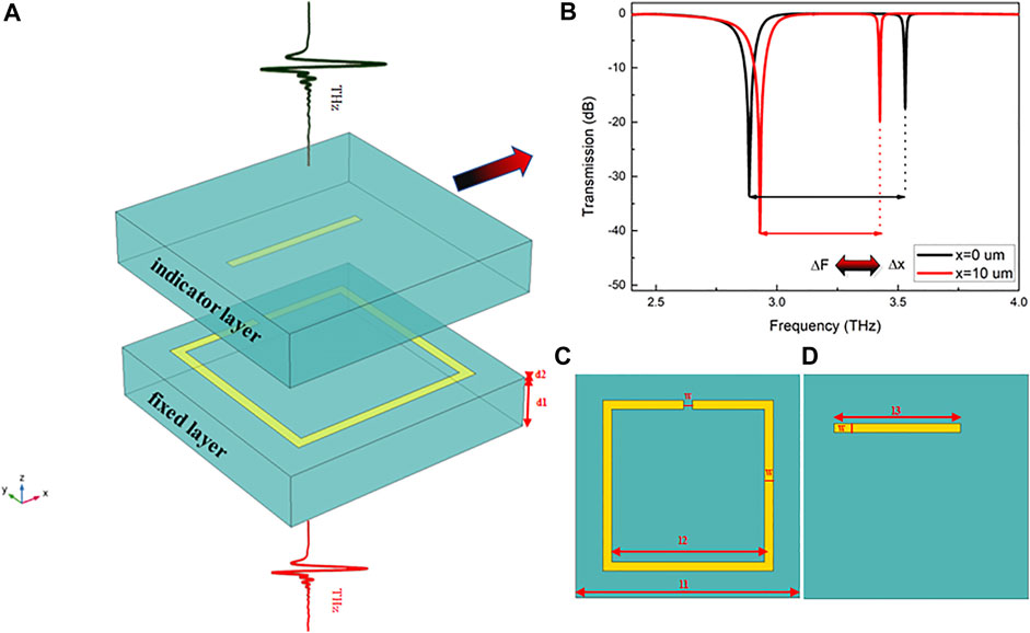
FIGURE 1. The schematic diagram of the proposed terahertz (THz) displacement sensor. (A) The schematic diagram of the proposed THz-DS unit. (B) The schematic diagram of the x displacement corresponds to the trough movement of the THz transmission spectrum. (C) The top view of the fixed layer of the proposed THz-DS. (D) The top view of the indicator layer of the proposed THz-DS.
To well clarify the detection mechanism of the displacement sensor, the COMSOL software was used to simulate and calculate the transmission spectra of the main elements and the overall structure of the sensor. Among them, the relative permittivity of the flexible substrate Mylar sheet is set to be 3.3; the Au split resonator ring is selected as the Drude model (Xu et al., 2018); the relative permittivity is set to conj (1−ωp2/(ω2 + I × γ × ω)); the plasma frequency is ωp = 1.367e16 rad/s; the damping coefficient is γ = 1.215e14 rad/s; ω is the frequency; the conductivity of Au in this band is σ = 4.09e-7 S/m; the perfectly matched layer (PML) boundary condition is set at perpendicular to the THz light transmission direction, that is, parallel to the two ends of the element structure (xy plane); and the thickness of PML is set to be 160 μm. The remaining boundaries are set to the Floquet periodicity boundary.
Figure 2 shows the THz transmission spectrum of the THz-DS structure when the THz plane light is vertically incident (the THz light propagates along the z-direction and the electric field of the THz wave is along the +x-direction). Each valley of transmission peak corresponds to a resonance mode of the structure. The black line is the THz transmission spectrum of the fixed layer where SRR is located, and three transmission valleys appear in this frequency band. The red spectral line is the THz transmission spectrum of the indicator layer where DI is located, and there is one transmission valley in this frequency band. The blue spectral line is the THz transmission spectrum of THz-DS. The three resonance transmission valleys are generated by the resonant coupling between the fixed layer and the indicator layer. To further study the physical mechanism of the proposed THz-DS and explain the resonance modes of the three resonance fronts in Figure 2, the electric field distributions in the z-direction on the surface of the THz-DS structure at the three resonance transmission valleys are calculated and plotted (Figure 3). It can be seen that there is a very high electric field energy distribution at both ends of DI, which is consistent with the single-dipole resonance mode, indicating that the transmission valley (3.195 THz) generated by DI is caused by the dipole oscillation. Because the SRR structure as the typical metamaterial structure can achieve high-density electric or magnetic field concentration effects, the low-frequency resonance peak (0.75 THz) in the THz transmission spectrum is a typical LC resonance mode. The specific mechanism is that the electric field of the incident light is parallel to the direction of the opening, and thus, the induced charges continue to accumulate at the opening to form a capacitor structure. The induced charges move directionally in the metal ring to form a ring current, which excites the magnetic dipole to generate a magnetic field, and the arm of the metal ring is equivalent to an inductance to store magnetic energy. In the whole structure, the electromagnetic waves radiated by alternating electrical and magnetic energy form resonance with the THz waves. Therefore, the low-frequency resonance can be equivalent to an LC tank, which is usually called electromagnetic resonance or LC resonance (Dominik et al., 2018). The resonant frequency is as follows:
where L is the equivalent inductance of the SRR, which is proportional to the geometric area of the THz incident field passing through the SRR, and C is the equivalent capacitance at the opening, which can be calculated by using the parallel plate capacitor model:
where ε is the dielectric constant, S is the facing area at the opening, d is the width of the opening, and k is the electrostatic constant, respectively
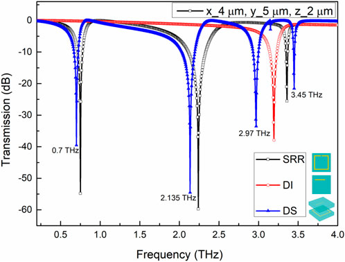
FIGURE 2. The THz transmission spectra of the structures for the proposed THz-DS.

FIGURE 3. The distributions of electric field Ez on the surface of the proposed THz-DS at the four resonant peaks of (A) 0.7 THz, (B) 2.135 THz, (C) 2.97 THz, and (D) 3.45 THz, respectively.
When the THz transmission spectrum passes through the SRR, the high-frequency resonance transmission valley is derived from the resonant modes such as dipoles, quadrupoles, and hexapoles. The specific mechanism is that when the THz electric field is incident on the metamaterial, the charge oscillation generates a linear oscillating current, similar to the electric dipole. In this case, an alternating electromagnetic field can be generated in the nearby space, which directly resonates with the THz wave to form a resonance transmission valley, and thus, it is called the dipole resonance of the electric response (Singh et al., 2010; Chen et al., 2017) as shown in the black color line in Figure 2. The transmission valleys at 2.24 and 3.36 THz are originated from the four-dipole resonance and the six-dipole resonance, respectively. Combined with Figure 3A in the z-direction electric field distribution diagram of THz-DS at 0.7 THz, the induced charges gather at the opening and form an obvious annular current in the metal ring, which can be determined in the transmission spectrum of Figure 2. The transmission valley at 0.7 THz is mainly generated by the LC resonance of the SRR in the fixed layer. Combined with Figure 3B in the z-direction electric field distribution of THz-DS at 2.135 THz, the charges are split into four dipoles in the metal ring. The distribution of the annular current shows that the transmission valley 2.135 THz is generated by the quadrupole resonance of the SRR in the fixed layer. Likewise, combined with the electric field distribution patterns of Figures 3C, D, the resonance transmission valley 2.97 and 3.45 THz are generated by the cocoupling of the dipole resonance of DI in the mobile layer and the six-dipole resonance of the SRR in the fixed layer. Therefore, the information of the third and fourth resonant peaks can reflect the position state of DI relative to SRR. When the relative displacement of DI and SRR changes, it will result in the shift of the two peak positions, and in turn, the value of the two peak positions can characterize the displacement change.
In addition, to better optimize the parameters of the THz-DS structure, except for the optimal parameters for the simulation performance of the width of the Mylar substrate, SRR, and DI, the length of DI was carefully simulated and studied. As shown in Figure 4, the transmission spectrum of THz-DS with the changes in the length of DI (l3) is 0–38 µm in Figure 4A and the relationship between the length of DI and the third resonance transmission valley in Figure 4B. The transmittance is the smallest when the length of DI is 28 μm, and the displacement change value is the most obvious. Therefore, the length of DI in the THz-DS structure is selected as 28 µm. Moreover, to test whether the test results of THz-DS would be affected by the thickness of the Mylar substrate, the transmission spectrum of THz-DS with the different thickness of Mylar was simulated, and it was found that the difference ΔF for positions of the third and fourth resonance transmission valleys had not changed, as shown in Figure 5. It can be seen that the ΔF of the THz transmission spectrum of THz-DS had not changed in the range of 10–30 μm, indicating that the test results cannot be affected by the thickness of Mylar.
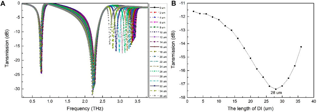
FIGURE 4. The numerical simulation method for choosing the optimal length of DI of THz-DS. (A) Transmission spectra of the proposed THz-DS with different lengths of DI. (B) The relationship diagrams between the length of DI and the transmission of the No. 3 resonance frequency.
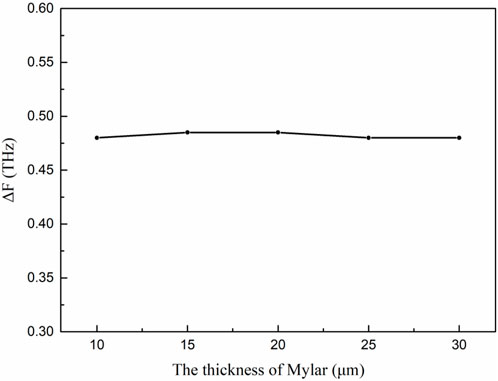
FIGURE 5. The ΔF of the THz transmission spectrum of THz-DS with the different thickness of Mylar.
S, Q, and FOM were used to evaluate the performance of the THz 3D displacement sensor. Among them, the sensitivity S is a physical quantity that characterizes the sensor’s ability to respond strongly to changes in the measured object (Allsop and Neal, 2019). According to the characteristics of THz-DS, the expression of S is as follows:
where Δf represents the change of the resonance frequency shift, the unit is GHz, and Δr represents the change of the displacement, which are the change of Δx, Δy, and Δz in the three directions, respectively, and the unit is μm, and thus, the unit of sensitivity S is GHz/μm
In addition to S, the Q value is an important parameter to characterize the sensor performance, which can reflect the properties of optical resonance (Ma et al., 2020). The larger the Q value is, the smaller the loss of the resonance system and the narrower the resonance peak are. The definition of the resonance peak Q value is given as formula (4):
where f0 is the center frequency of the resonance peak, FWHM is the full width at half maximum, and the Q value is dimensionless. The larger the Q value, the sharper the resonance transmission valley
To compare the performance of sensors working more scientifically in different electromagnetic bands, the researchers introduced the FOM value (Sherry et al., 2006), which is defined as in formula (5):
The FOM value can comprehensively quantify the two parameters of sensitivity and resolution. The higher the sensitivity of the sensor and the smaller the FWHM value, the better the sensing performance. In short, the Q value reflects the sharpness of the resonance transmission valley, S reflects the shift of the resonance transmission valley, and the FOM value comprehensively considers these two factors to characterize the overall performance of the sensor. The larger the FOM value, the better the overall performance of the sensor.
Our group has developed a THz imaging system based on the conventional THz-TDS system (Neu and Schmuttenmaer, 2018) with a THz displacement sensor and have studied their high-resolution imaging applications. The Ti:sapphire femtosecond laser is used for pumping and detecting THz wave, which has a center wavelength of 800 nm, a pulse width of 100 fs, and an average output power of 960 mW. The THz pulse is generated by illuminating the InAs with pump pulses. The probe pulses are modulated by the THz pulse signal through ZnTe. By varying the time delay between two pulses, the THz pulse waveform can be detected through the electrooptic sampling measurement. The THz radiation spot diameter on the samples is approximately 1 mm. The fixed layer of the THz displacement sensor is placed at the THz beam waist in the THz imaging system, whereas the displacement indicating the layer of the THz displacement sensor is attached to the back of the imaging target synchronous motion.
The THz-DS transmission spectra of the measured displacements in the x-direction ranging from 1 to 10 μm and with an interval step of 1 μm were simulated and calculated using the COMSOL Multiphysics simulation software. As shown in Figure 6A, the positions of the two resonance transmission valleys in the low-frequency region can have a negligible change, whereas the positions of the third and fourth resonance transmission valleys in the high-frequency region can have the evident red-shifted change, which can be attributed to the coupling changed between the DI dipole resonance of the indicator layer and the SRR hexapole resonance of the fixed layer, and the distance between the third and the fourth transmission valleys gradually decreases with the increase of displacement. The displacement in the x-direction and the difference ΔF between the position of the third resonance transmission valley and the fourth transmission valley can be extracted. The relationship between the x-direction displacement and the transmission valley position difference ΔF is obtained by the second-order polynomial curve fitting (Figure 6B) using formula (6):
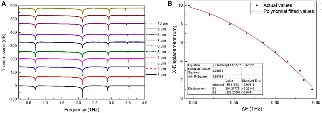
FIGURE 6. The x displacement measurement method for the THz displacement sensor. (A) Transmission spectra of the proposed THz-DS with different x displacements. (B) The relationship diagrams between x displacement and the ΔF.
As can be observed from Figure 6B, the fitting degree is as high as 0.99399. Therefore, one can easily obtain the x-direction displacement value utilizing formula (6), just only by inputting the ΔF. At the same time, the optimal values of S, Q, and FOM can be obtained by using formulas (3–5), as given in Table 1, where S is 25 GHz/μm, Q value is as high as 194.67, and FOM is 1.67. It is indicated that the displacement sensor can be used to effectively measure the x-direction displacement with high-sensitivity.
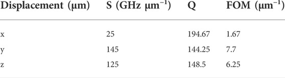
TABLE 1. The performance parameters of the terahertz (THz) displacement sensor.
In the same way, the THz-DS transmission spectrum with the displacement range of 1–10 μm in the z-direction and the interval step of 1 μm is calculated through the simulation. The change frequency of △F between the positions of the third and the fourth resonance transmission valleys gradually increases with the increase of the z-direction displacement (Figure 7A). The relationship between the z-direction displacement and the transmission valley position difference ΔF can be obtained by the second-order polynomial curve fitting (Figure 7B) by using formula (7). Meanwhile, three performance parameters of the sensor are obtained: S is 125 GHz/μm, Q value is 148.5, and FOM is 6.25, as shown in Table 1.
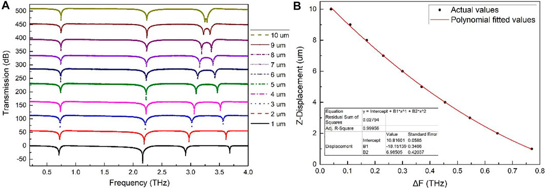
FIGURE 7. The z displacement measurement method for the THz displacement sensor. (A) Transmission spectra of the proposed THz-DS with different z displacement. (B) The relationship diagrams between the z displacement and the ΔF.
In this study, the THz-DS transmission spectrum with a displacement range of 1–7 µm in the y-direction and an interval step of 1 µm was also simulated and calculated. The distance of ΔF between the positions of the third and the fourth resonance transmission valleys gradually increases with the increase of y-direction displacement, as displayed in Figure 8. Formula (8) shows the relationship between the y-direction displacement and the transmission valley position difference ΔF, and three performance parameters of the sensor can be obtained: S is 145 GHz/μm, Q value is 144.25, and FOM is 7.7, as shown in Table 1.
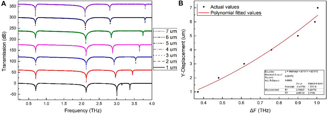
FIGURE 8. The y displacement measurement method for the THz displacement sensor. (A) Transmission spectra of the proposed THz-DS with different y displacements. (B) The relationship diagrams between the y displacement and the ΔF.
Through the research on the displacement detection in the three directions, it is concluded that the 3D THz displacement sensor can achieve high-precision and high-sensitivity detection in the three directions of XYZ, particularly from the perspective of the displacement detection sensitivity with the optimal value for the y-direction and z-direction, whereas the x-direction can be detected displacement with high Q. Overall, the 3D displacement sensor has the superior performances as demonstrated by the high FOM of three directions. Therefore, according to the needs of actual detection, based on the unique double-layer structure of the sensor, high-sensitivity displacement measurement can be achieved by simply measuring the amount of metal indicator line change corresponding to the change in the THz transmission trough of the displacement sensor and finally to realizing the target precise positioning in the THz high-sensitivity imaging process. For the stationary imaging target, according to its actual shape, the fixed layer and the displacement indicating the layer of the THz displacement sensor are respectively attached to different positions with large fluctuations in the shape of the edge of the target to form a combined body, which is then placed in the THz imaging system. The precise positioning of the edge of the target body can be obtained by analyzing the THz transmission spectrum valley changed value of each displacement indication layer, and the spatial size can be accurate to 1 μm. As for the moving imaging target, the fixed layer of the THz displacement sensor is placed at the THz beam waist in the THz imaging system, and the displacement indicates that the layer of the sensor is attached to the back of the imaging target. The moving target can be calibrated with an accuracy of 1 μm through the displacement values in the x-direction, y-direction, and z-direction, which are calculated by formulas (6–8) based on the change frequency of △F between the positions of the third and the fourth resonance transmission valleys in the high-frequency region.
In this study, to overcome the problems of coherent fringes, laser speckle, edge loss, smear, and ghost in the existing THz imaging technology, a promising method based on the Mylar flexible substrate layer, metal split resonator ring, and metal indicator was proposed. With the aid of the concentration effect of the THz electric field achieved by the coupling between the SRR and DI, the high-sensitivity detection method for displacement can be developed. By optimizing the main parameters of the sensor, the quadrupole/hexapole resonance of the SRR and the dipole resonance of the DI can be completely overlapped and coupled, which greatly enhances the interaction between the displacement and the electromagnetic field, and the sensitivity of the sensor can reach as high as 145 GHz/μm. Moreover, the sensor can have a good stability Q value and high FOM value under different displacement values. In addition, the displacement sensor has a good direction selection and simple operation characteristics, which makes it promising in practical applications. To effectively solve the problems of coherent fringes, laser speckle, edge loss, smear, and ghost, on the one hand, the resolution can be greatly improved by optimizing the parameters of the THz displacement sensor. On the other hand, the DI of the THz displacement sensor closely fits the target body, enabling it to accurately characterize the shape and edge of the object being measured. The proposed 3D THz displacement sensor can have excellent characteristics such as high-sensitivity, flexible adjustment, good stability, and broad application prospects in THz imaging and microdisplacement detection.
The raw data supporting the conclusions of this article will be made available by the authors, without undue reservation, to any qualified researcher.
TM and GZ conceived the study, performed part of the analyses, carried out the interpretation of the results, and drafted the manuscript. WH and WL designed and simulated the THz spectra of the 3D THz displacement sensor. HL and CF contributed to the fitting equation of the relationship between the variation parameters and the sensitivity and critically reviewed the manuscript. All authors read and approved the final manuscript.
This research was supported by the National Key R&D Program of China (2021YFB3200100), the National Natural Science Foundation of China (62071312), the Shanxi Scholarship Council (2020-135), the Youth Science and Technology Research Foundation of Shanxi Province (201901D211432), the Science and Technology Innovation Program of Institutions of Higher Education of Shanxi Province (2020L0466), and the Key R & D Project of Datong City (2020019).
The authors declare that the research was conducted in the absence of any commercial or financial relationships that could be construed as a potential conflict of interest.
All claims expressed in this article are solely those of the authors and do not necessarily represent those of their affiliated organizations, or those of the publisher, the editors, and the reviewers. Any product that may be evaluated in this article, or claim that may be made by its manufacturer, is not guaranteed or endorsed by the publisher.
Aksimsek, S. (2020). Design of an ultra-thin, multiband, micro-slot based terahertz metamaterial absorber. J. Electromagn. Waves Appl. 34 (16), 2181–2193. doi:10.1080/09205071.2020.1809532
Allsop, T., and Neal, R. (2019). A review: evolution and diversity of optical fibre plasmonic sensors. Sensors 19 (22), 4874. doi:10.3390/s19224874
Bandyopadhyay, A., and Sengupta, A. (2021). A review of the concept, applications, and implementation issues of terahertz spectral imaging technique. IETE Tech. Rev. 11, 471–489. doi:10.1080/02564602.2020.1865844
Chen, L., Liao, D. G., Guo, X. G., Zhao, J. Y., Zhu, Y. M., and Zhuang, S. L. (2019). Terahertz time-domain spectroscopy and micro-cavity components for probing samples: a review. Front. Inf. Technol. Electron. Eng. 20 (5), 591–607. doi:10.1631/FITEE.1800633
Chen, L., Xu, N. N., Singh, L., Cui, T. J., Singh, R. J., Zhu, Y. M., et al. (2017). Defect-induced fano resonances in corrugated plasmonic metamaterials. Adv. Opt. Mater. 5 (8), 1600960. doi:10.1002/adom.201600960
Chiam, S. Y., Singh, R., Gu, J., Han, J., Zhang, W., and Bettiol, A. A. (2009). Increased frequency shifts in high aspect ratio terahertz split ring resonators. Appl. Phys. Lett. 94 (6), 064102. doi:10.1063/1.3079419
Chiam, S. Y., Singh, R., Zhang, W., and Bettiol, A. A. (2010). Controlling metamaterial resonances via dielectric and aspect ratio effects. Appl. Phys. Lett. 97 (19), 191906. doi:10.1063/1.3514248
Christian, D., and Bolivar, P. H. (2007). Frequency selective surfaces for high sensitivity terahertz sensing. Appl. Phys. Lett. 91 (18), 184102. doi:10.1063/1.2805016
Cubukcu, E., Shuang, Z., Park, Y. S., Bartal, G., and Xiang, Z. (2009). Split ring resonator sensors for infrared detection of single molecular monolayers. Appl. Phys. Lett. 95 (4), 043113. doi:10.1063/1.3194154
Dominik, W-V., Angus, H-J., Harald, G-L-S., and Rainer, L. (2018). Prism coupling of high-Q terahertz whispering-gallery-modes over two octaves from 0.2 THz to 1.1 THz. Opt. Express 26 (24), 31190–31198. doi:10.1364/OE.26.031190
Driscoll, T., Andreev, G. O., Basov, D. N., Palit, S., Smith, D. R., Jokerst, N. M., et al. (2007). Tuned permeability in terahertz split-ring resonators for devices and sensors. Appl. Phys. Lett. 91 (6), 062511–062513. doi:10.1063/1.2768300
Driscoll, T., Andreev, G. O., Basov, D. N., Palit, S., Ren, T., Mock, J., et al. (2007). Quantitative investigation of a terahertz artificial magnetic resonance using oblique angle spectroscopy. Appl. Phys. Lett. 90 (9), 092508. doi:10.1063/1.2679766
Gu, Q. C., Lv, J. T., Mo, X. W., and Jiang, X. X. (2022). High aspect ratio metamaterials and their applications. Sensors Actuators A Phys. 335, 113376. doi:10.1016/j.sna.2022.113376
Hibbins, A. P., Evans, B. R., and Sambles, J. (2005). Experimental verification of designer surface plasmons. Science 308 (5722), 670–672. doi:10.1126/science.1109043
Lee, S., Baek, S., Kim, T., Cho, H., Lee, S., Kang, J., et al. (2020). Metamaterials for enhanced optical responses and their application to active control of terahertz waves. Adv. Mat. 32 (35), 2000250. doi:10.1002/adma.202000250
Ma, A., Zhong, R., Wu, Z., Wang, Y., Yang, L., Liang, Z., et al. (2020). Ultrasensitive THz sensor based on centrosymmetric f-shaped metamaterial resonators. Front. Phys. 8, 441. doi:10.3389/fphy.2020.584639
Mittleman, D. M. (2018). Twenty years of terahertz imaging [invited]. Opt. Express 26 (8), 9417. doi:10.1364/OE.26.009417
Neu, J., and Schmuttenmaer, C. A. (2018). Tutorial: an introduction to terahertz time domain spectroscopy (THz-TDS). J. Appl. Phys. 124 (23), 231101. doi:10.1063/1.5047659
O’Hara, J. F., Withayachumnankul, W., and Al-Naib, I. (2012). A review on thin-film sensing with terahertz waves. J. Infrared Millim. Terahertz Waves 33 (3), 245–291. doi:10.1007/s10762-012-9878-x
Pendry, J. B., Holden, A. J., Robbins, D. J., and Stewart, W. J. (1999). Magnetism from conductors and enhanced nonlinear phenomena. IEEE Trans. Microw. Theory Tech. 47 (11), 2075–2084. doi:10.1109/22.798002
Recur, B., Younus, A., Salort, S., Mounaix, P., Abraham, E., Desbarats, P., et al. (2011). Investigation on reconstruction methods applied to 3D terahertz computed tomography. Opt. Express 19 (6), 5105–5117. doi:10.1364/OE.19.005105
Sabah, C., Dincer, F., Karaaslan, M., Unal, E., Akgol, O., and Demirel, E. (2014). Perfect metamaterial absorber with polarization and incident angle independencies based on ring and cross-wire resonators for shielding and a sensor application. Opt. Commun. 322, 137–142. doi:10.1016/j.optcom.2014.02.036
Shen, Y. C., Gan, L., Stringer, M., Burnett, A., Davies, A. G., Shen, H., et al. (2009). Terahertz pulsed spectroscopic imaging using optimized binary masks. Appl. Phys. Lett. 95 (23), 231112–231113. doi:10.1063/1.3271030
Sherry, L. J., Jin, R., Mirkin, C., Schatz, G., and Duyne, R. V. V. (2006). Localized surface plasmon resonance spectroscopy of single silver triangular nanoprisms. Nano Lett. 6 (9), 2060–2065. doi:10.1021/nl061286u
Singh, R., Al-Naib, I. A. I., Koch, M., and Zhang, W. L. (2010). Asymmetric planar terahertz metamaterials. Opt. Express 18 (12), 13044–13050. doi:10.1364/OE.18.013044
Singh, R., Cao, W., Al-Naib, I. A. I., Cong, L., Withayachumnankul, W., and Zhang, W. (2014). Ultrasensitive terahertz sensing with high-q fano resonances in metasurfaces. Appl. Phys. Lett. 105 (17), 171101. doi:10.1063/1.4895595
Srivastava, Y. K., Cong, L., and Singh, R. (2017). Dual-surface flexible THz fano metasensor. Appl. Phys. Lett. 111 (20), 201101. doi:10.1063/1.5000428
Stark, J. A. (2000). Adaptive image contrast enhancement using generalizations of histogram equalization. IEEE Trans. Image Process. 9 (5), 889–896. doi:10.1109/83.841534
Tao, H., Strikwerda, A. C., Liu, M., Mondia, J. P., Ekmekci, E., Fan, K., et al. (2010). Performance enhancement of terahertz metamaterials on ultrathin substrates for sensing applications. Appl. Phys. Lett. 97 (26), 261909. doi:10.1063/1.3533367
Wang, W., Yan, F. P., Tan, S. Y., Zhou, H., and Hou, Y. F. (2017). Ultrasensitive terahertz metamaterial sensor based on vertical split ring resonators. Photonics Res. 5 (6), 571–577. doi:10.1364/PRJ.5.000571
Xu, C., Fan, W., and Chao, S. (2018). Multiple plasmonic resonance excitations on graphene metamaterials for ultrasensitive terahertz sensing. Carbon 133, 416–422. doi:10.1016/j.carbon.2018.03.051
Xu, J. J., Liao, D. G., Gupta, M., Zhu, Y. M., Zhuang, S. L., Singh, R., et al. (2021). Terahertz microfluidic sensing with dual-torus toroidal metasurfaces. Adv. Opt. Mat. 9 (15), 2100024. doi:10.1002/adom.202100024
Xu, N., Singh, R., and Zhang, W. (2016). High-Q lattice mode matched structural resonances in terahertz metasurfaces. Appl. Phys. Lett. 109 (2), 021108. doi:10.1063/1.4958730
Keywords: terahertz displacement sensor, metamaterials, ring resonator, high-sensitivity sensing, numerical simulation
Citation: Meng T, Zhao G, Liu H, Li W, Feng C and Hu W (2022) 3D flexible displacement sensor for highly sensitive movement measurement assisted by the terahertz imaging system. Front. Mater. 9:957909. doi: 10.3389/fmats.2022.957909
Received: 31 May 2022; Accepted: 29 July 2022;
Published: 30 August 2022.
Edited by:
Zixiong Sun, University of Twente, NetherlandsReviewed by:
Bala Tripura Sundari B, Amrita Vishwa Vidyapeetham University, IndiaCopyright © 2022 Meng, Zhao, Liu, Li, Feng and Hu. This is an open-access article distributed under the terms of the Creative Commons Attribution License (CC BY). The use, distribution or reproduction in other forums is permitted, provided the original author(s) and the copyright owner(s) are credited and that the original publication in this journal is cited, in accordance with accepted academic practice. No use, distribution or reproduction is permitted which does not comply with these terms.
*Correspondence: Guozhong Zhao, Z3Vvemhvbmctemhhb0BtYWlsLmNudS5lZHUuY24=; Weidong Hu, aG9vd2luZEBiaXQuZWR1LmNu
Disclaimer: All claims expressed in this article are solely those of the authors and do not necessarily represent those of their affiliated organizations, or those of the publisher, the editors and the reviewers. Any product that may be evaluated in this article or claim that may be made by its manufacturer is not guaranteed or endorsed by the publisher.
Research integrity at Frontiers
Learn more about the work of our research integrity team to safeguard the quality of each article we publish.