 Kaiyuan Zhao
 Qichang Zhang1
 Wei Wang
94% of researchers rate our articles as excellent or good
Learn more about the work of our research integrity team to safeguard the quality of each article we publish.
Find out more
ORIGINAL RESEARCH article
Front. Mater., 26 July 2022
Sec. Smart Materials
Volume 9 - 2022 | https://doi.org/10.3389/fmats.2022.956182
This article is part of the Research TopicEnergy Harvesting by Smart MaterialsView all 4 articles
Wind energy is a typical foreseeable renewable energy source. This study constructs and optimizes a variable cross-section cantilever-based piezoelectric energy harvester for low-speed wind energy harvesting. The Galerkin approach is usually used to discretize the continuum model and then get the ordinary differential equations. However, this method is more suitable for calculating uniformity than the variable cross-sectional beam model. To solve this problem, we proposed an improved piecewise Galerkin approach for discretizing the continuum model with a variable cross section. By modifying the boundary expressions and modal functions between segments, it can improve both computation speed and accuracy. COMSOL simulations demonstrate that natural frequencies calculated via the improved method are more accurate than those of the traditional Galerkin method. The method of multiple scales is applied to determine the output power and critical wind velocity. A distinctive numerical approach is presented for shape optimization by combining the analytical calculation method with the particle swarm optimization (PSO) technique for low-speed wind energy harvesting. Additionally, the logic function is chosen to produce the optimal shape’s fitting expression for engineering applications. With all the improvements, the output power of a variable cross-section beam-based harvester reaches as much as 3.668 times that of a uniform beam model, demonstrating the importance of structural optimization for this type of energy harvesters. Finally, experiments are set up to verify the optimization procedure. Actually, it builds an analytical framework for the adaptive selection of variable-section piezoelectric cantilever wind-induced vibration energy harvesters.
In the past two decades, vibration energy harvesting has been extensively studied to replace traditional chemical batteries for powering small electronic devices (Wei and Jing, 2017). Vibration sources available for harvesting can be mainly classified into two categories: base vibration and flow-induced vibration (Zou et al., 2019). Flow-induced vibration energy harvesting has flourished in recent years with the basic premise of providing small levels of energy to power electronic sensors installed in outdoor areas, tunnels, exhaust ducts, etc. Various fluid–structural interaction techniques were proposed to transduce a portion of the flow’s kinetic energy into mechanical motion, which in turn is transformed into electrical energy via an electromechanical coupling mechanism, e.g., piezoelectric or electromagnetic (Abdelkefi, 2016). Unlike traditional rotating electromagnetic generators, piezoelectric energy harvesters are very simple to design and fabricate and hence, can be easily mass produced and designed for integration. Piezoelectric material-based flow-induced vibration energy harvesting technologies include, but are not limited to, vortex-induced vibrations, flutter, and the galloping instability. Galloping-induced vibration has the characteristics of large oscillation amplitude and a wide range of operating wind speeds. Therefore, galloping piezoelectric energy harvesters (GPEHs) have been explosively researched (Abdelkefi et al., 2012; Abdelmoula and Abdelkefi, 2017; Wang et al., 2020). However, the optimal design of GPEH is still difficult, for example, there are only a few studies on the optimization of piezoelectric beam geometry. In this study, PSO coupled with theoretical expressions of the GPEH are used to efficiently search for the global optimum design of the piezoelectric cantilever beam. This energy harvester can be applied to the active wind micro-sensor and self-powered sensing systems.
The optimized design of the GPEH is divided into two main areas: the windward bluff body and the piezoelectric cantilever beam. Many kinds of research on windward bluff bodies have been studied (Abdelkefi, 2016; Wang et al., 2020). Javed and Abdelkefi (2017) investigated the impacts of using different aerodynamic load representations on the galloping square cross-sectional cylinder dynamics in the GPEH system. They inclined a square cross-section cylinder, investigating GPEH prone to galloping oscillation (Javed and Abdelkefi, 2018). Zhu et al. (2021) conducted a comparative study for different cross-sectional cylinders (square, triangle, and trapezoid) experiencing the galloping. Liu et al. (2018) proposed and designed a three-blade bluff body for wind energy harvesting. In the optimization of GPEH, there are limited results for piezoelectric cantilever beams. Wang et al. (2019) first compared the output power of three variable-section piezoelectric cantilever beams in GPEH. However, there are many optimizations in the base vibration energy harvester regarding the geometry of piezoelectric cantilever beams. For example, Nowak et al. (2020) optimized the uniform beam’s length, width, and thickness. Salmani et al. (2010), Salmani and Rahimi (2018), Pradeesh and Udhayakumar (2019), and Hajheidari et al. (2020) concluded that the exponentially tapered piezoelectric beam improves the voltage per mass of the energy harvester. Chen et al. (2020) and He et al. (2020) showed an increase in the output voltage of a trapezoidal cantilever beam than a rectangular cantilever. Raju et al. (2020) revealed that the harvester consists of the tapered section from the root followed by a rectangular section that increases the output voltage by 91.3% compared with the energy harvester considered with a uniform cantilever beam. These findings point the way to the design of piezoelectric cantilever beams. These works are mainly based on the beam optimization of mathematical functions of beams, but in fact, the global optimization analysis is more reasonable for structural design. In our previous study, we used a combination of wind tunnel experiments and data-driven methods to optimize the cross-sectional shape of the bluff body (Zhao et al., 2019). Based on these research results, the geometry of the piezoelectric cantilever beam is globally optimized in this study.
There are few articles on the global optimization of piezoelectric cantilever beam shapes in energy harvesters. In order to manipulate the shape of the piezoelectric cantilever beam in a global sense, parameterization techniques are necessary. The parameterization of the piezoelectric cantilever beam needs to satisfy the conditions of flexibility, smoothness, and uniqueness. Therefore, it is crucial to choose the appropriate parameterization method to represent the shape of the piezoelectric cantilever beam. Then, one can use these parameters as a design space to maximize the output power of the energy harvester by searching through the design space. For the complex optimization problem with many design variables, a considerably high-dimensional design space is required, which results in an exponential increase in computation time. For the energy harvester optimization problem, the optimization time is reduced in two main aspects: the computing time of the output power of each energy harvester and the optimization method. There are two main approaches for computing the output power of energy harvesters: the finite element method (FEM) based on simulation software (Thein and Liu, 2017; Mohamed et al., 2021) and the analytical calculation method based on theoretical mechanics and nonlinear dynamics (Daqaq, 2015; Javed and Abdelkefi, 2019). For the energy harvester, the result of the FEM is more accurate. However, the complex design space of size and shape variables forces the computational cost of global optimization to be very expensive (Delalat et al., 2021; Mohamed et al., 2021). Feng et al. (2020) proposed an improved analytical method for the analytical expression of the output power of the energy harvester to eradicate the computational burden. However, based on the present research results, the analytical method needs to be further optimized and proved for variable-section piezoelectric cantilever beams (Yang et al., 2016; Feng et al., 2020). The selection of optimization methods should ensure convergence as quickly as possible on the basis of global optimization (Bonyadi and Michalewicz, 2017). At present, genetic algorithm (GA) and PSO have recently demonstrated their success and popularity in optimization applications methods, and they are more in line with our optimization requirements (Daxini and Prajapati, 2019). The aforementioned analysis shows that there are three main difficulties in the global optimization of the piezoelectric cantilever shape for energy harvesters: 1) parameterization of the piezoelectric cantilever beam shape; 2) accurate and efficient computation of the output power of energy harvester system; and 3) selection of the optimization method.
In this study, the analytical expression of the system output power is calculated by using the improved piecewise Galerkin method and the multiple scales method, and the beam shape is expressed parametrically using the piecewise cubic Hermite interpolation (PCHIP) function in this research. Matlab codes are developed for the PSO method integrated with the analytic expression of the energy harvester output power to globally optimize the shape of the piezoelectric cantilever beam. The rest of the study is organized as follows. The mathematical model of the variable cross-section GPEH is described in Section 2. In Section 3, the improved piecewise Galerkin is proposed and verified, and the analytical expression of the system output power is also derived. In Section 4, the optimization process and the optimization results of the variable cross-section piezoelectric cantilever beam shape are described and compared with the simulation results. In Section 5, experimental verification is performed.
In order to study the vibration power generation capacity of the piezoelectric cantilever with different shapes, it is assumed that the length and root width of the piezoelectric cantilever beam base and piezoelectric sheet are the same. As shown in Figure 1A, the width of its root is

FIGURE 1. (A) Schematic diagram of the variable cross-sectional energy harvester. (B) Top view of the piezoelectric cantilever structure.
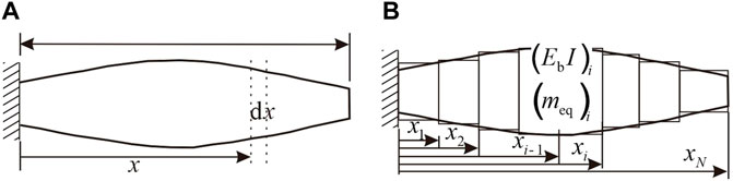
FIGURE 2. Sketch of the variable section cantilever beam. (A) Before segmentation; (B) after segmentation.
By drawing on the mathematic modeling method of Erturk and Inman (2008) and Abdelmoula and Abdelkefi (2016), the governing equation of motion of variable cross-section cantilever-based piezoelectric wind energy harvester can be written as
where
The boundary condition of the system is
It is obvious that Eq. 1 is a partial differential equation of beam with variable a cross section. For this variable section beam, the section area and stiffness are functions of the section position, which makes the constant coefficients of the differential equation in the traditional method become a variable coefficient. As a result, it is impossible to directly apply the traditional Galerkin method to analyze the modal function and natural frequency of those beams with variable sections. In order to solve this problem and analyze its vibration characteristics, we proposed an improved piecewise Galerkin method based on the literature (Can, 2009; Feng et al., 2020).
In the study by Feng et al. (2020), the modal function of each small segment is polynomial, which is convenient and concise. However, the accuracy of calculation results may be affected by the over-fitting of polynomials. We expressed the modal functions of each segment as the combination of trigonometric functions and hyperbolic functions to prevent the over-fitting phenomenon. The boundary conditions of each section are modified to the exact value at that point, rather than the equivalent value represented by the average. These calculation processes avoid the un-smoothness of modal functions and improve the accuracy of calculation results.
First, the governing equation of motion for undamped free vibrations of a variable cross-section beam is considered as
The Galerkin method (Patil and Althoff, 2011; Peradze, 2011) can be used to solve Eq. 13 by separating the spatial and temporal functions as
which can be substituted into Eq. 13 to give
For Eq. 15, based on the traditional Galerkin method, if
where β is the eigenvalue of the system, which is related to the natural frequency of the system. A, B, C, and D are unknown constants determined by the boundary conditions at the left and right ends of the beam. Under the given boundary conditions, the analytical solution of the modal function of a beam with a uniform beam can be given by Eq. 17, and the characteristic equation of its natural frequency can be obtained from this equation. However, this method is more suitable for calculating the uniformity than the variable cross-section beam model.
As shown in Figure 2, based on the idea of segmentation, the variable cross-section beam is divided into several connected segments. Each segment is regarded as a constant cross-section segment when the number of segments is enough (Feng et al., 2020).
It is assumed that the length of the ith segment is
Based on the analytical expression of the modal function of the beam, the modal function of the i-th segment of the beam can be defined as follows:
where
In Eq. 20,
It should be noted in Eq. 22 that ω is the natural circular frequency of transverse vibration of a variable cross-section beam rather than the natural circular frequency of the i-th segment of the beam.
Similarly, the modal function of the (i+1)-th segment is then
According to the continuity of displacement, rotation angle, bending moment, and shear force at the connection point
Equation 24 is improved based on the research results of Can (2009). In the literature, the expression of bending stiffness
Using Eqs 20, 23, and 24, iteration equations become
where
The relationship between
where
Each element in the Z matrix is a function of the natural frequency ω, which establishes the relationship between the indeterminate coefficients
The improved piecewise Galerkin method can not only obtain high-precision results of mode function and natural frequency of the beam with an arbitrary variable section, but also shorten the time required for calculation greatly. This method is used here for structural analysis to circumvent frequently encountered issues with a traditional grid-based technique like FEM in shape optimization such as heavy reliance on quality mesh for accurate solutions needing remeshing. To demonstrate the effectiveness of the improved piecewise Galerkin method, results obtained through the proposed method are compared with other methods of the past literature.
In order to verify the feasibility and universality of the aforementioned methods, this section takes the FEM results as the accurate results, uses the Galerkin method, piecewise Galerkin method (Feng et al., 2020) and improved the piecewise Galerkin method, respectively, for the same model, and compares their calculation accuracy. As shown in Eq. 32, the width function is selected as different order functions of position coordinates. The beam is a uniform beam, when n = 0 and it is a variable section beam, when
The root width of the variable section beam is wb1 = 40 × 10−3 m, and the free end width is wb2 = 8 × 10⁻³ m. Here, we take

TABLE 1. Physical parameters and geometric dimensions of the variable cross-section energy harvester.
The natural frequencies of the first mode of the five beams are calculated by COMSOL simulation, the Galerkin, piecewise Galerkin, and the improved piecewise Galerkin methods. From Table 2, it can be seen that the error of the approximate mode method will be infinitely enlarged when solving a large deformation variable cross-sectional cantilever beam. Moreover, the number of segments of piecewise Galerkin method also affects accuracy. Comparing results with N = 10, it is obvious that the result from improved piecewise Galerkin has a higher precision than the traditional Galerkin method and piecewise Galerkin method. Therefore, the effectiveness and accuracy of the improved piecewise Galerkin method are proved by theoretical and COMSOL simulation analysis.
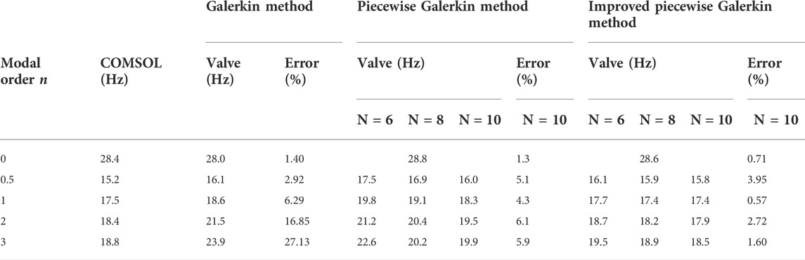
TABLE 2. Natural frequencies of the variable cross-sectional beam.
To further verify the accuracy and general application of the method, we used COMSOL with MATLAB port to combine MATLAB software with COMSOL software to perform calculations. A set of random numbers is generated using MATLAB as the geometry of the beam, and the set of random numbers is arranged in a descending order and imported into COMSOL software to generate the base beam. The number of random samples is 300, and the wind speed is set between 10 and 20 m/s. The output voltage error and output power error are shown in Figure 3A and Figure 3B. The voltage error is less than 6%, and the power error is less than 10%, which meets the calculation error requirement.
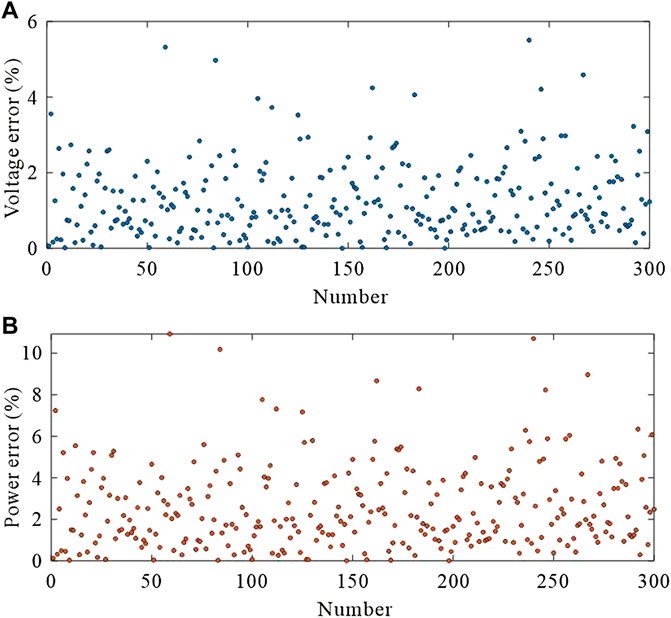
FIGURE 3. (A) Voltage error. (B) Power error.
We used the method of multiple scales to solve Eqs. 30 and 31 to decrease the computational effort. Therefore, Eqs. 30 and 31 yield the following two equations
where
An approximate analytical expression for the steady-state response of Eqs. 33 and 34 can be obtained by following the detailed procedure by Daqaq (2015). The steady-state magnitude of the deflection and voltage is given by
The output power can be obtained by squaring Eq. 36 and dividing by the load resistance, which yields
The critical wind velocity of the energy harvester is
The output power and the critical wind velocity are important evaluation indexes of the GPEH.
We use a parametric optimization approach for obtaining the near-optimal shape of the piezoelectric cantilever beam. To manipulate the shape of the beam, techniques of parameterization are necessary. Several methods, including discrete, Bezier, linear interpolation, quadratic interpolation, Spline, polynomial, piecewise polynomial, and PCHIP methods, can be used to parameterize and generate different geometries in engineering applications. However, the design of the piezoelectric cantilever beam has to meet the following requirements: 1) provide smooth and realistic beam shapes, 2) design variables ability to cover wide design search space, and 3) computationally economical. Based on the aforementioned requirements and due to the fact, PCHIP avoids overshoots and can accurately connect the flat regions. Therefore, PCHIP curve is used to generate the geometry of the piezoelectric cantilever beam in this study.
The most popular methods for global optimization are PSO and GA (Shaaban et al., 2020a). Sun et al. (2018) summarized the advantages of PSO corresponding to the lower memory capacity consumption than GA. Shaaban et al. (2020b) and Barbieri et al. (2015) performed comparisons between PSO and GA related to the shape optimization of the horn problem showing the merits of using PSO. For a detailed PSO algorithm, refer to Bonyadi and Michalewicz (2017).
In this study, PSO is used to optimize the shape of the piezoelectric cantilever beam to increase the output power of the energy harvester. Matlab codes are developed for the PSO method integrated with the analytical solution based on the piecewise Galerkin method as a solver. The PCHIP curve is applied to parameterize the shape of the piezoelectric cantilever beam, and the coordinates of the control points are designated to act as optimization parameters. The objective of shape optimization is to find the best geometric profile to maximize the output power of the energy harvester, and the local search and global search are carried out. The mathematical formula for objective function is Eq. 37. To summarize the entire process, the flowchart of the proposed shape optimization technique is shown in Figure 4.
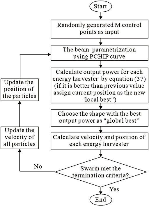
FIGURE 4. Flowchart for the optimal design of the shape of a piezoelectric cantilever beam using PSO.
In most research results, the optimization of the piezoelectric cantilever beam ignores the allowable strain of material, which represents an ideal situation. Nowak et al. (2020) studied the optimal aspect ratio of the cantilever beam using a static method. The research results of Wang et al. (2019) and Salmani and Rahimi (2018) showed that designing a beam with exponentially varying shapes can obtain the largest power density and reduce the cost of the energy harvester. These studies reveal the main geometric relationships affecting the output power of the piezoelectric cantilever beam. Therefore, it is important to investigate the global optimization results while neglecting the allowable strain of material.
However, structural integrity and durability over a long time are important considerations in designing energy harvesters for real-life applications. Inherent brittleness and fatigue due to the cyclic electromechanical loading on lead zirconate titanate (PZT) material might cause the abrupt failure of the device if material strength is not considered in the design process. On the other hand, an unchecked design may result in a situation where maximum stress or strain is well below the allowable limit, leading to poor utilization of the material. Allowable strains of some commonly used MFC materials are given in Table 1. Fatigue strain values given in Table 3 are the limit values of strain allowed in the material when subjected to alternate fields or stresses. It is clearly evident in the table that the strength of piezoelectric materials is much lower compared to the strength of substrate materials such as steel, aluminum, and bronze. This fact accentuates the importance of the allowable strain of piezoelectric material in designing the energy harvester. In this study, two pieces of piezoelectric MFC employ for the experiment. We use 605ppm as the allowable strain of piezoelectric material to optimize the shape of the cantilever. The strain value at the root of the uniform piezoelectric cantilever is greater than the strain limit of MFC material without considering allowable strain. Therefore, in the following calculation, we change the thickness of the piezoelectric cantilever to avoid fracture of piezoelectric material due to excessive deformation. Other parameters are shown in Table 1 and remain unchanged.
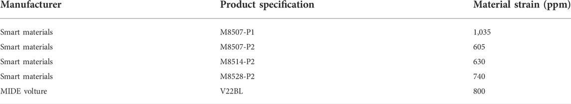
TABLE 3. Material strength of commonly used piezoelectric materials.
Assuming that the allowable strain of the piezoelectric material is infinite, that is, the topological shape of the piezoelectric cantilever beam is optimized without considering the material strength. Considering the design requirements of the piezoelectric cantilever beam, the upper and the lower limits of width are considered as 40 and 8 mm, respectively. Other physical parameters and geometric dimensions are shown in Table 1. When M equals 10 and the ambient wind speed is 13 m/s, convergence in solution was obtained after 30 iterations and Figure 5A shows the history of objective function values obtained during the process. The shape of the optimized beam is plotted in Figure 5B. Since the shape of the optimized beam is symmetrical about the x-axis, the shape given in Figure 5B shows the optimization curve of the symmetrical part of the beam. At this time, the output power of the energy harvester is 65.5 mW.
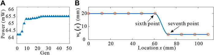
FIGURE 5. (A) Convergence of the objective function in terms of the number of iterations. (B) Optimal beam model.
However, as shown in Figure 5B, there is no intermediate value between the sixth point and the seventh point, only the maximum and minimum values, so it is impossible to judge whether the optimization result is the optimal result. Optimized shapes for operating points M from 10 to 40 are studied in this case. The variation of the objective function for different operating points M during the optimization processes is shown in Figure 6A and the shape of the optimized beam for different M is shown in Figure 6B. In this optimization case, the solution is not unique and the maximum output energy increases with the increase of M. From Figure 6B, it can be seen that, when M is 40, the maximum output power is 73.3 mW. As shown in Figure 6B, with the increase in M, the shape of the optimal beam gradually approaches the shape of the stepped beam. When the values of M are 30 and 40, the output power of the optimized beam is very close, and their shape is also very close. However, more operating points M unnecessarily increase the computational cost, because the convergence algebra increases with the increase of optimization parameters. On the other hand, fewer operating points make the optimization results unreliable. Considering these two aspects comprehensively, 40 operating points are selected for optimization calculation in the following research process.
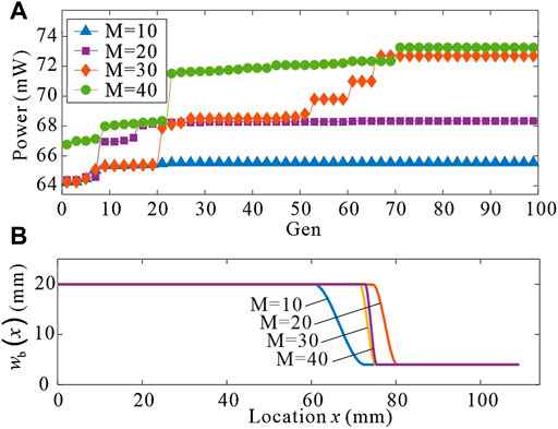
FIGURE 6. (A) Convergence of the objective function in terms of the number of iterations for different operating points M. (B) Optimal beam model for different operating points M.
In order to verify the correctness of the optimization results, at the same wind speed, we analyze the output power of the five piezoelectric cantilevers proposed in the third part. Figure 7A compares the output power of energy harvesters with five different piezoelectric cantilever’s shapes for beams having ended width equal 0–40 mm. The labels of beams with different shapes correspond to Eq. 32. As shown in Figure 7A, the maximum output power of the uniform beam is 15.1 mW and its width is 19.0 mm. The output power of the variable section beam is maximum when the width of the free end is the minimum value. Since the minimum value of the beam width is 8 mm, the maximum output of the variable section beam is between 36.8 and 48.7 mW within the design requirements. It is obvious from Figure 7A that the output power of the variable cross-section beam is 2.4–3.2 times that of the uniform beam.
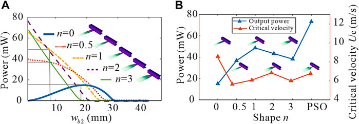
FIGURE 7. (A) Output power of the piezoelectric cantilever with different geometrical structures. (B) Output power and critical velocity of beams with different shapes.
Figure 7B compares the output power and critical velocity of the PSO optimized beam with the five beams proposed in Eq. 32. It is obvious that the output power of PSO optimized beam is much higher than that of other forms of beams, and the change of critical velocity is not very large.
As shown in Figure 8A, the optimized shape of the piezoelectric cantilever beam is calculated, when considering that the allowable strain of piezoelectric material is 605 ppm and the wind speed is 13 m/s. Figure 8B shows the corresponding convergence diagram. The output power of the optimized energy harvester is 4.6 mW.
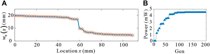
FIGURE 8. (A) Optimal beam mode. (B) Convergence of the objective function in terms of the number of iterations.
The strain distribution on the lower surface along the length of the uniform beam, variable cross-section beams, and the beam optimized by the PSO algorithm in the same wind speed environment are plotted in Figure 9A. From the figure, it can be seen that under the same conditions, the beam optimized by the PSO algorithm can effectively improve the uniformity of strain distribution compared with other shapes of beams, thus increasing the electrical energy generated by the piezoelectric material, which is more conducive to the efficiency of the wind-induced vibration energy harvester. A comparison of the output power of the beams with six different shapes is shown in Figure 9B. It can be seen that the output power of the piezoelectric cantilever beam optimized by the PSO method is 3.668 times larger than that of the other beams.
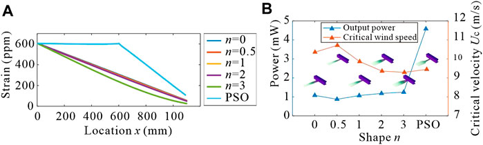
FIGURE 9. (A) Strain along the length of piezoelectric cantilever beams with different shapes. (B) Output power and critical velocity of beams with different shapes.
The optimal topology of the piezoelectric cantilever beam for different wind speeds when considering the upper limit of the material strain of 605 ppm is shown in Figure 10A. The optimal topology of the piezoelectric cantilever beam for different upper strain limit cases in the same wind speed environment is shown in Figure 10B.
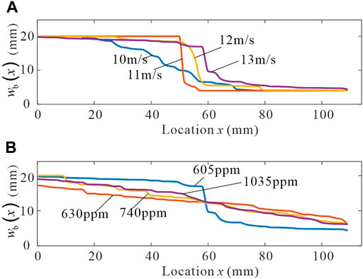
FIGURE 10. (A) Optimized beam at different wind speeds. (B) Optimized beam at different strain upper limits.
In order to facilitate engineering application, the logic function is utilized to fit the optimization results.
As shown in Eq. 39, the expression of the curve consists of four parameters. The nonlinear least square method is used to fit the width function of the optimized beam. The fitting results of the optimized piezoelectric cantilevers under different wind speeds are shown in Figure 11A.
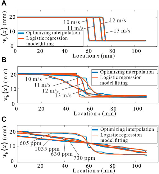
FIGURE 11. Fitting diagram of optimized beams at different conditions. (A) Comparison of the optimized beam curve and fitted function curve. (B) Fitting of the optimized beam at different wind speeds. (C) Fitting diagram of optimized beams at different strain upper limits.
From the nature of the logistic function and the fitted shape of the optimized beam at different wind speeds shown in Figure 11A, it can be inferred that the parameter k2 of the logistic function determines the shape of the optimized beam at different wind speeds. In this function, k3 = 158.069 is a constant, and k1 and k4 are related to the maximum and minimum values, i.e., k1≈wbmax/2, k4≈wbmin/2. Therefore, the exponential fit of k2 can accurately predict the shape of the optimized beam at different wind speeds, as shown in Eq. 40, where U is the wind speed, P1 = −222.2, P2 = −0.00628, P3 = 1,418, and P4 = −0.3221.
The logistic function is used to fit the analysis to the optimized beam with different strains on the requirement. Figure 11B shows the shape fit of the optimized beam for different wind speeds at an upper strain limit of 605 ppm. The expression of the width function of the optimized beam is Eq. 39, and the expression of k2 is Eq. 40, where P1 = −222.2, P2 = −0.00628, P3 = 1,418, and P4 = −0.3221. The shape fit of the optimized beam with different allowable strains at a wind speed of 13 m/s is illustrated in Figure 11C.
The software COMSOL is used to validate the theoretical results. The geometric and material properties of the piezoelectric cantilever are given in Table 1. Considering the material strength, the transient response and output power of piezoelectric cantilever beams with different shapes in the environment of wind speed of 13 m/s are calculated. The output voltage and power of piezoelectric cantilever beams with different shapes and the strain nephogram at their maximum deformation are shown in Figures 12A,B. It is obvious that the output voltage of the piezoelectric cantilever optimized by PSO is the largest. Compared with the other five kinds of beams, the stress change of the optimized beam is uniform, and the strain of most areas remains near the material strain limit, which maximizes the working efficiency of piezoelectric materials.
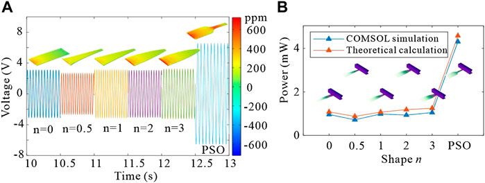
FIGURE 12. (A) Transient response and strain nephogram of the piezoelectric cantilever beam. (B) Comparison of output power between simulation calculation and theoretical calculation of beams with different shapes.
In order to further verify the correctness of the conclusion, the energy harvester considering the material strength of piezoelectric material is experimentally verified.
Wind tunnel experiments are carried out in the “low turbulence reflux wind tunnel” finished at the Department of Mechanics, Tianjin University, and the experimental results compare with the theoretical and simulation results. Figure 13A displays the physical characteristics of the main body of the wind tunnel tested, and Figure 13B gives the schematic representation of the experimental apparatus. Two MFC piezoelectric sheets connect in series with the rheostat. The voltage signals at both ends of the rheostat are output to the data acquisition. The laser displacement sensor monitors the displacement signal of the cylinder and inputs them to the data acquisition. The computer controls the operation and storage of the data acquisition system.
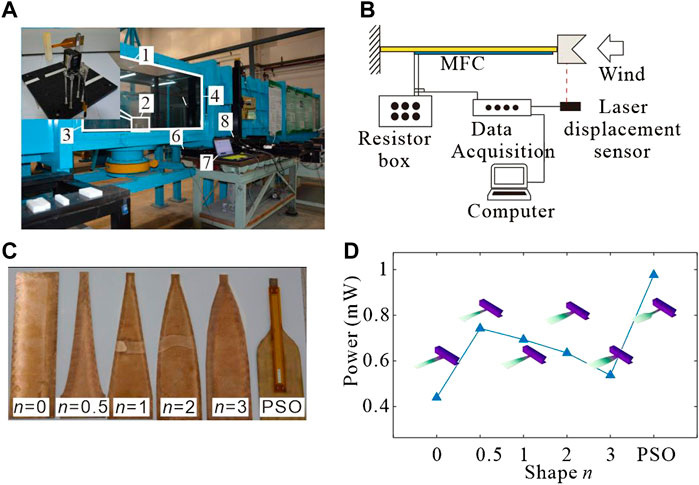
FIGURE 13. (A) Wind tunnel experiment equipment. 1) Wind tunnel test section; 2) energy harvester for testing; 3) wind inlet; 4) wind outlet; 5) hot wire anemometer; 6) data acquisition; 7) computer; and 8) rheostat. (B) Schematic representation of the experimental apparatus. (C) Base of the piezoelectric cantilever beam. (D) Experimental results of the output power of beams with different shapes.
Figure 13C provides the physical view of the six piezoelectric cantilever beam substrates in the wind tunnel experiments. Since the special shape of the MFC piezoelectric sheet cannot be customized in the market, the rectangular piezoelectric sheet of the M8507-P2 model is used for comparison experiments and qualitative analysis. As shown in Figure 13C, the placement of the piezoelectric sheet unifies at the position near the free end of the cantilever beam in the experiment.
Figure 13D shows the output power of different shapes of beams for the wind speed of 13 m/s in wind tunnel experiments. From the figure, it can be seen that the output power of the optimized beam by PSO is the highest in the same area of piezoelectric material pasted. This conclusion qualitatively verifies that the optimized beam has a more uniform strain at all points during the deformation process and gives full play to the piezoelectric material. Through the rectifier circuit, this GPEH can supply power to milliwatt level sensors.
A global optimization scheme based on a variable-section piezoelectric cantilever beam for wind-induced vibration energy harvesters is proposed by coupling the improved piecewise Galerkin method and the PSO optimization method. The finite element simulation and wind tunnel experiments validate the accuracy of the improved piecewise Galerkin method in the dynamic calculation of the variable cross-section beam. Due to the optimization process being combined with numerical and analytical algorithms, the step of redrawing the mesh in the shape optimization process is avoided compared to the simulation optimization, which greatly saves computational costs.
Considering the material strength of piezoelectric material, the shape of the optimized beam is similar to the logic function. The output power of the optimized beam is more than three times that of the uniform beam. Finally, the logic function is utilized to fit the optimized beam, and the function and corresponding parameter values of the optimized beam widths under different conditions are given.
The cantilever harvester proposed in the study achieves a better uniform strain distribution. The evenly distributed strain contributes to less energy dissipation during the charge redistribution process, which causes a larger voltage and energy conversion efficiency. This study provides a new global approach to the optimization of the wind-induced vibration energy harvester in practical application.
The development of wind energy harvester will adhere to the trends of miniaturization, multi-function, and integration. Miniaturization increases the adaptability of energy harvester applications. With the wireless requirement of the environmental monitoring network, the energy harvester should be integrated with sensors to realize the multi-function of the device. The self-powered wind sensing device is expected to realize a complete intelligent system, including energy, signal processing, and wireless transmission unit. With the continuous development, the wind energy harvester will provide a new energy supply and sensing scheme for wireless environmental monitoring networks and the Internet of things.
The raw data supporting the conclusion of this study will be made available by the authors, without undue reservation.
KZ and WW have contributed to the conceptualization, analysis of data, and drafting of the manuscript. QZ and JH have contributed to the formal analysis. WW, JH, and SH have contributed to the analysis of data, interpretation of data, and revision of the manuscript. All the authors have contributed to the final proofreading and approval of the version for publication.
The authors appreciate the support of the National Natural Science Foundation of China (Grant Nos. 12172248, 11772218, 11872044, 12021002, 12072233, 12072234, and 12132010), the National Key Research and Development Program of China (Grant No. 2020YFB2007202), and the Natural Science Foundation of Tianjin (Grant No. 20JCQNJC01070).
The authors declare that the research was conducted in the absence of any commercial or financial relationships that could be construed as a potential conflict of interest.
All claims expressed in this article are solely those of the authors and do not necessarily represent those of their affiliated organizations, or those of the publisher, the editors, and the reviewers. Any product that may be evaluated in this article, or claim that may be made by its manufacturer, is not guaranteed or endorsed by the publisher.
Abdelkefi, A. (2016). Aeroelastic energy harvesting: A review. Int. J. Eng. Sci. 100, 112–135. doi:10.1016/j.ijengsci.2015.10.006
Abdelkefi, A., Hajj, M. R., and Nayfeh, A. H. (2012). Power harvesting from transverse galloping of square cylinder. Nonlinear Dyn. 70 (2), 1355–1363. doi:10.1007/s11071-012-0538-4
Abdelmoula, H., and Abdelkefi, A. (2017). Investigations on the presence of electrical frequency on the characteristics of energy harvesters under base and galloping excitations. Nonlinear Dyn. 89 (4), 2461–2479. doi:10.1007/s11071-017-3597-8
Abdelmoula, H., and Abdelkefi, A. (2016). The potential of electrical impedance on the performance of galloping systems for energy harvesting and control applications. J. Sound Vib. 370, 191–208. doi:10.1016/j.jsv.2016.01.037
Barbieri, R., Barbieri, N., and de Lima, K. F. (2015). Some applications of the PSO for optimization of acoustic filters. Appl. Acoust. 89, 62–70. doi:10.1016/j.apacoust.2014.09.007
Bonyadi, M. R., and Michalewicz, Z. (2017). Particle swarm optimization for single objective continuous space problems: A review. Evol. Comput. 25 (1), 1–54. doi:10.1162/EVCO_r_00180
Can, C. (2009). Master. Chengdu: Southwest Jiaotong University.A fast calculation methods and application for vibration characteristic of beam with variable cross-section
Chen, L., Chang, L., Jing, H., and Li, H. (2020). Design and study of rigid-flexible coupled piezoelectric energy harvester. Smart Mat. Struct. 29 (5), 055012. doi:10.1088/1361-665X/ab78b9
Daqaq, M. F. (2015). Characterizing the response of galloping energy harvesters using actual wind statistics. J. Sound Vib. 357, 365–376. doi:10.1016/j.jsv.2015.08.003
Daxini, S. D., and Prajapati, J. M. (2019). Structural shape optimization with meshless method and swarm-intelligence based optimization. Int. J. Mech. Mat. Des. 16 (1), 167–190. doi:10.1007/s10999-019-09451-3
Delalat, K., Zamanian, M., and Firouzi, B. (2021). Improving performance of piezoelectric energy harvester under electrostatic actuation using cavity. Coupled Syst. Mech. 10 (5), 429–451. doi:10.12989/csm.2021.10.5.429
Erturk, A., and Inman, D. J. (2008). A distributed parameter electromechanical model for cantilevered piezoelectric energy harvesters. J. Vib. Acoust. 130 (4). doi:10.1115/1.2890402
Feng, J., Chen, Z., Hao, S., and Zhang, K. (20202020). An improved analytical method for vibration analysis of variable section beam. Math. Problems Eng., 1–11. doi:10.1155/2020/3658146
Hajheidari, P., Stiharu, I., and Bhat, R. (2020). Performance of tapered cantilever piezoelectric energy harvester based on Euler-Bernoulli and Timoshenko Beam theories. J. Intelligent Material Syst. Struct. 31 (4), 487–502. doi:10.1177/1045389x19891526
He, X., Wen, Q., Wen, Z., and Mu, X. (2020). “A mems piezoelectric vibration energy harvester based on trapezoidal cantilever beam array,” in 33rd IEEE International Conference on Micro Electro Mechanical Systems (MEMS)) (IEEE), 532–535.
Javed, U., and Abdelkefi, A. (2019). Characteristics and comparative analysis of piezoelectric-electromagnetic energy harvesters from vortex-induced oscillations. Nonlinear Dyn. 95 (4), 3309–3333. doi:10.1007/s11071-018-04757-x
Javed, U., and Abdelkefi, A. (2017). Impacts of the aerodynamic force representation on the stability and performance of a galloping-based energy harvester. J. Sound Vib. 400, 213–226. doi:10.1016/j.jsv.2017.04.013
Javed, U., and Abdelkefi, A. (2018). Role of the galloping force and moment of inertia of inclined square cylinders on the performance of hybrid galloping energy harvesters. Appl. Energy 231, 259–276. doi:10.1016/j.apenergy.2018.09.141
Liu, F.-R., Zou, H.-X., Zhang, W.-M., Peng, Z.-K., and Meng, G. (2018). Y-type three-blade bluff body for wind energy harvesting. Appl. Phys. Lett. 112 (23), 233903. doi:10.1063/1.5029415
Mohamed, K., Elgamal, H., and Kouritem, S. A. (2021). An experimental validation of a new shape optimization technique for piezoelectric harvesting cantilever beams. Alexandria Eng. J. 60 (1), 1751–1766. doi:10.1016/j.aej.2020.11.024
Nowak, R., Pietrzakowski, M., and Rumianek, P. (2020). Influence of design parameters on bending piezoelectric harvester effectiveness: Static approach. Mech. Syst. Signal Process. 143, 106833. doi:10.1016/j.ymssp.2020.106833
Patil, M. J., and Althoff, M. (2011). Energy-consistent, Galerkin approach for the nonlinear dynamics of beams using intrinsic equations. J. Vib. Control 17 (11), 1748–1758. doi:10.1177/1077546310385777
Peradze, J. (2011). On the accuracy of the Galerkin method for a nonlinear dynamic beam equation. Math. Methods Appl. Sci. 34 (14), 1725–1732. doi:10.1002/mma.1478
Pradeesh, E. L., and Udhayakumar, S. (2019). Investigation on the geometry of beams for piezoelectric energy harvester. Microsyst. Technol. 25 (9), 3463–3475. doi:10.1007/s00542-018-4220-8
Raju, S. S., Umapathy, M., and Uma, G. (2020). Design and analysis of high output piezoelectric energy harvester using non uniform beam. Mech. Adv. Mater. Struct. 27 (3), 218–227. doi:10.1080/15376494.2018.1472341
Salmani, H., Rahimi, G. H., and Afshari, S. S. (2019). Optimization of the shaping function of a tapered piezoelectric energy harvester using tabu continuous ant colony system. J. Intelligent Material Syst. Struct. 30 (20), 3025–3035. doi:10.1177/1045389x19873391
Salmani, H., and Rahimi, G. H. (2018). Study the effect of tapering on the nonlinear behavior of an exponentially varying width piezoelectric energy harvester. J. Vib. Acoust. 140 (6). doi:10.1115/1.4039932
Shaaban, A. M., Anitescu, C., Atroshchenko, E., and Rabczuk, T. (2020a). Isogeometric boundary element analysis and shape optimization by PSO for 3D axi-symmetric high frequency Helmholtz acoustic problems. J. Sound Vib. 486, 115598. doi:10.1016/j.jsv.2020.115598
Shaaban, A. M., Anitescu, C., Atroshchenko, E., and Rabczuk, T. (2020b). Shape optimization by conventional and extended isogeometric boundary element method with PSO for two-dimensional Helmholtz acoustic problems. Eng. Analysis Bound. Elem. 113, 156–169. doi:10.1016/j.enganabound.2019.12.012
Sun, S. H., Yu, T. T., Nguyen, T. T., Atroshchenko, E., and Bui, T. Q. (2018). Structural shape optimization by IGABEM and particle swarm optimization algorithm. Eng. Analysis Bound. Elem. 88, 26–40. doi:10.1016/j.enganabound.2017.12.007
Thein, C. K., and Liu, J.-S. (2017). Numerical modeling of shape and topology optimisation of a piezoelectric cantilever beam in an energy-harvesting sensor. Eng. Comput. 33 (1), 137–148. doi:10.1007/s00366-016-0460-3
Wang, J., Geng, L., Ding, L., Zhu, H., and Yurchenko, D. (2020). The state-of-the-art review on energy harvesting from flow-induced vibrations. Appl. Energy 267, 114902. doi:10.1016/j.apenergy.2020.114902
Wang, K. F., Wang, B. L., Gao, Y., and Zhou, J. Y. (2019). Nonlinear analysis of piezoelectric wind energy harvesters with different geometrical shapes. Arch. Appl. Mech. 90 (4), 721–736. doi:10.1007/s00419-019-01636-8
Wei, C., and Jing, X. (2017). A comprehensive review on vibration energy harvesting: Modelling and realization. Renew. Sustain. Energy Rev. 74, 1–18. doi:10.1016/j.rser.2017.01.073
Yang, W. D., Li, Y. D., and Wang, X. (2016). Tunable electromechanical coupling of a carbon nanotube-reinforced variable cross-section nanoswitch with a piezoelectric effect. J. Phys. D. Appl. Phys. 49 (33), 335304. doi:10.1088/0022-3727/49/33/335304
Zhao, K., Zhang, Q., and Wang, W. (2019). Optimization of galloping piezoelectric energy harvester with V-shaped groove in low wind speed. Energies 12 (24), 4619. doi:10.3390/en12244619
Zhu, H., Tang, T., Zhou, T., Cai, M., Gaidai, O., Wang, J., et al. (2021). High performance energy harvesting from flow-induced vibrations in trapezoidal oscillators. Energy 236, 121484. doi:10.1016/j.energy.2021.121484
Keywords: piezoelectric cantilever, topological optimization, wind energy harvester, piecewise Galerkin, particle swarm optimization
Citation: Zhao K, Zhang Q, Wang W, Han J and Hao S (2022) Topological optimization of a variable cross-section cantilever-based piezoelectric wind energy harvester. Front. Mater. 9:956182. doi: 10.3389/fmats.2022.956182
Received: 30 May 2022; Accepted: 28 June 2022;
Published: 26 July 2022.
Edited by:
Huaxia Deng, University of Science and Technology of China, ChinaReviewed by:
Ruilan Tian, Shijiazhuang Tiedao University, ChinaCopyright © 2022 Zhao, Zhang, Wang, Han and Hao. This is an open-access article distributed under the terms of the Creative Commons Attribution License (CC BY). The use, distribution or reproduction in other forums is permitted, provided the original author(s) and the copyright owner(s) are credited and that the original publication in this journal is cited, in accordance with accepted academic practice. No use, distribution or reproduction is permitted which does not comply with these terms.
*Correspondence: Wei Wang, d2FuZ3dlaWZyYW5jaXNAdGp1LmVkdS5jbg==; Jianxin Han, aGFuamlhbnhpbkB0anUuZWR1LmNu
Disclaimer: All claims expressed in this article are solely those of the authors and do not necessarily represent those of their affiliated organizations, or those of the publisher, the editors and the reviewers. Any product that may be evaluated in this article or claim that may be made by its manufacturer is not guaranteed or endorsed by the publisher.
Research integrity at Frontiers
Learn more about the work of our research integrity team to safeguard the quality of each article we publish.