- 1School of Physics, Beihang University, Beijing, China
- 2Beijing Key Laboratory of Advanced Nuclear Materials and Physics, Beihang University, Beijing, China
In this work, we propose an efficient numerical method to study the effects of microstructures on the effective diffusion coefficient of the diffusion component in materials. We take the diffusion of hydrogen (H) atoms in porous polycrystalline tungsten (W) as an example. The grain structures and irradiated void microstructures are generated by using the phase-field model. The effective diffusion coefficients of H in these microstructures are obtained by solving the steady-state diffusion equation, using a spectral iterative algorithm. We first validate our simulation code for calculating the effective diffusion coefficient by using three simple examples. We then investigate the effects of the grain morphology and porosity on the effective diffusion coefficient of H in W. Regardless of whether the grain boundary is beneficial to the diffusion of H or not, it is found that the effective diffusion coefficient of H along the elongated grain direction in columnar crystals is always greater than that in isometric crystals. The increase of the porosity can significantly decrease the effective diffusion coefficient of H from the simulations of the porous W. A correlation of converting the two-dimensional (2D) effective diffusion coefficient into three-dimensional (3D) in the porous and polycrystalline W is fitted by using our simulation data, respectively. Two fitted correlations can be used to predict the synergistic effect of the porosity and grain boundary on the effective diffusion coefficient of H in W. Consequently, our simulation results provide a good reference for understanding the influence of the complex microstructures on H diffusion, and may help to design W-based materials for the fusion reactor.
1 Introduction
Due to the energy crisis caused by the exploitation of the limited fossil energy, nuclear fusion energy with many potential advantages such as abundant raw materials, pollution-free products, and high energy efficiency, has been constantly studied. The Tokamak, a magnetically confined fusion device, is considered to be the most likely future fusion device (Artsimovich, 1972). In the nuclear fusion reactor environment, tungsten (W) has been considered as one of the most promising candidate materials for plasma-facing materials (PFMs), owing to its advantages of high melting point, good thermal conductivities, as well as low sputtering rate (Bolt et al., 2004; Cottrell, 2004). However, PFMs will be irradiated by high energy neutron (14 MeV) in combination with the high temperature (300 < T < 2000 K) (Li et al., 2017), which will inevitably induce microstructure changes such as grain boundary migration (Stepper, 1972; Vaidya and Ehrlich, 1983; Mannheim et al., 2018), and second-phase formation (voids/dislocations caused by clustering of point defects (Hasegawa et al., 2014; Hu et al., 2016), precipitates formed by the precipitation of the transmutation elements (Hasegawa et al., 2016)), etc. Besides, hydrogen (H) and its isotope escaped from the plasma can penetrate through the W surfaces and diffuse inside the bulk under plasma irradiation (El-Kharbachi et al., 2014; Hodille et al., 2014; Grisolia et al., 2015). The interaction between H and the defect microstructures may result in a set of safety issues of W such as surface blistering (Zhou H. et al., 2019), embrittlement (Louthan et al., 1972), and cracking (Ueda et al., 2005), which can notably degrade the mechanical and thermal properties of W and thus reduce its service lifetime. In addition, H and its isotope are very expensive reactants, finding a way to recycle them can greatly reduce the cost. The diffusion process of H and its isotope in such complex microstructures is extremely important. Therefore, understanding the effect of the microstructure on the diffusion of H is critical to improving the irradiation properties and reducing the cost of fuels.
Recently, numerous simulations and experimental studies have been conducted on the H diffusion in the bulk (Frauenfelder, 1969; Heinola et al., 2010a; Yang and Oyeniyi., 2017) and on the surface of W (Heinola and Ahlgren, 2010b; Xue and Hassanein, 2014; Yang and Wirth, 2019), as well as the effect of irradiated defects such as vacancies (Eleveld and Veen, 1994; Liu et al., 2009; Johnson and Carter, 2010), dislocations (Taketomi et al., 2008; Kimizuka and Ogata, 2011; Wang et al., 2019), and grain boundaries (Oudriss et al., 2012; Yu et al., 2014; González et al., 2015; Fu et al., 2021) on the H diffusion. The thermal desorption experimental results show that the H diffusion is influenced by various factors such as defect type (Jin et al., 2017), distribution (Fujita et al., 2017), temperature (Rieth et al., 2019), and annealing time (Sakurada et al., 2017). In addition, it is found that the desorption temperature of H from vacancies or voids does not exceed 800 K (Eleveld and Veen, 1994), and from grain boundaries is about 400–500 K (Hodille et al., 2017). And the molecular dynamics studies indicate that the H diffusion largely depends on the type of grain boundaries, i.e., certain types of grain boundaries (e.g.,
In this work, we demonstrate an efficient numerical method to study the effect of the microstructure on the H effective diffusion coefficient in W at relevant high temperatures. Grain structures and irradiated voids are considered as the main defect microstructures generated by using phase-field simulations, although other defect microstructures such as dislocations, precipitates, and gas bubbles can also be easily incorporated in the model. A spectral iterative algorithm (Wang et al., 2016; Li et al., 2022) is used to solve the stationary diffusion equation based on the phase-field microstructures to obtain the effective diffusion coefficient. The current method is only applied at high temperature or there is no interaction between the diffusion component and microstructure, where H atoms can be eventually desorbed from grain boundaries and voids consisting with the thermal desorption experimental observations (Eleveld and Veen, 1994; Hodille et al., 2014). Using this method, the effects of grain boundaries, voids, and their synergistic effect on the effective diffusion coefficient of H are systematically investigated in W. Two sets of correlations that can be used to transfer the two-dimensional (2D) into three-dimensional (3D) effective diffusion coefficient are fitted based on our simulation results, which can be used to predict the effective diffusion coefficient of H in the porous polycrystalline W. We believe that this method provides a good reference for understanding the influence of the microstructure on the H diffusion in W, and offers an efficient way to study the effect of the complex microstructure on the effective diffusion coefficient in other similar systems.
2 Computational Details
2.1 Phase-Field Model of Microstructure Evolutions
Controlling the grain size is a common way to tune the thermal and mechanical properties of the polycrystalline W. Within the phase-field model, a set of continuous non-conservative phase variables
where
The local microstructural free energy density can be formulated as (Fan and Chen, 1997; Krill and Chen, 2002)
where the first term describes a multi-well potential with a minimal value zero located at
The gradient energy terms contributed by the grain boundaries are written as
where
The evolution of the grain parameters is controlled by the Allen-Cahn equation (Allen and Cahn, 1972; Allen and Cahn, 1973),
where
A high density of point defects will be produced in W due to the high-energy neutron irradiation (Eleveld and Veen, 1994; Hasegawa et al., 2014; Hasegawa et al., 2016; Hu et al., 2016). Although the interstitial atoms and vacancies are always generated in pairs, we only consider the evolution of vacancies based on the fact that the diffusion coefficient of the interstitial atom is at least 103 magnitudes larger than that of the vacancy in W at 300 < T < 2000 K (Hao et al., 2020). Therefore, the diffusion of vacancies is the rate-controlling process in the formation of voids and the interstitial atoms can be always considered at the equilibrium state. This scenario was also used in previous work to study the effect of the void evolution on effective thermal conductivities in W (Wang et al., 2018). And it will not affect our main conclusions since the objective of this work is to investigate the effects of the porosity and void size on the effective diffusion coefficient of H in W.
In the phase-field model, a conservative phase variable
where
The gradient energy term contributed by the void-matrix interface is written as
where
The temporal and spatial evolution equations of the phase variable and concentration can be described by the Allen-Cahn (Allen and Cahn, 1972; Allen and Cahn, 1973) and Cahn-Hilliard equations (Cahn and Hilliard, 1958; Cahn and Hilliard, 1958) as
where
where
According to the assumption of the KKS model that the total concentration is a mixture of two phases and the chemical potential is the same at every position in the system (Kim et al., 1999; Kim, 2007), the concentrations satisfy the following two equations,
To sum up, the evolution Eqs. 9, 10 can be rewritten as
The semi-implicit FFTW numerical method is used to solve the Eqs. 4, 14, 15 (Chen and Shen, 1998). A Newton’s method is adopted to solve the nonlinear Eqs. 12, 13 for each time step.
2.2 Effective Diffusion Coefficient of H
Once we have the phase-field simulated grain structures and voids in W, we can investigate the effects of these microstructure evolutions on the effective diffusion coefficient of H. To do so, we solve the steady-state diffusion equation,
where
where
Accordingly, the stationary distribution of the H concentration can be separated into linear and nonlinear parts, which corresponds to the homogeneous and inhomogeneous diffusion coefficient, respectively, i.e.,
where
Based on the Fick’s first law, the flux of the H concentration along the j-direction is expressed as
where
Finally, the effective diffusion coefficient tensor
where
To solve the steady-state diffusion equation shown in Eq. 16, a spectral iterative method is adopted, which has been used to solve the heat conduction equation in previous work (Wang et al., 2016; Li et al., 2022). In order to facilitate the reader’s understanding, we present the details of the solution process here. Firstly, combining the Eqs 18, 19, the Eq. 16 can be rewritten as,
Then rearranging the Eq. 22, we get
After that, by taking the Fourier transform on both sides of Eq. 23, we have,
where
Thus, we can get
where
To sum up, the total concentration distribution
Once we have the total concentration
2.3 Simulation Details and Parameters
To simulate the grain growth and void microstructure evolutions, the phase-field Eqs. 4, 14, 15 are numerically solved with periodic boundary conditions. The time step for the grain growth is set at 2.4 s, and the grid spacing
The input parameters for simulating the void evolutions under irradiation are set as follows. The sizes of the simulation domain are set as 256
The diffusion coefficients of H in the bulk, grain boundary, and void are required to calculate the effective diffusion coefficient of H in W. Previous atomistic simulations have listed the diffusion coefficient of H in the bulk is 5.13
3 Results and Discussions
We first use three simple structures having analytical solutions of the effective diffusion coefficient to validate our simulation code. We then quantitively calculate the effective diffusion coefficient of H in the polycrystalline and porous W. A correlation of converting the 2D effective diffusion coefficient into 3D in the porous polycrystalline W is fitted by using our simulation data, respectively. The effects of the grain morphology, porosity, and their synergistic effect on the effective diffusion coefficient of H are systematically investigated.
3.1 Simulation Code Validation
Three simple structures are used to fully validate our simulation code for calculating the effective diffusion coefficient of the diffusion component, including a two-phase structure consisting of two different arrangements of slabs (parallel and perpendicular to each other), a spherical structure embedded in a cubic box, and a 3D isometric crystalline structure. The calculated effective diffusion coefficients are compared with the analytical solutions to verify our simulation code.
3.1.1 Two Slab Structures for Validation
We first use a two-phase system with a simple slab structure to validate the code since it has an analytical solution. Two different configurations of the two-phase system are constructed. One is that these two slabs are parallel to each other (Figure 1A), while the other one is that they are perpendicular to each other (Figure 1B). For the first structure shown in Figure 1A, the effective diffusion coefficient along the X and Y direction can be described analytically as (Hart, 1957; Jiang et al., 2021)
where
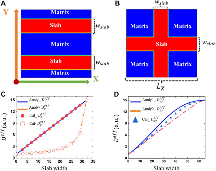
FIGURE 1. A two-phase system with a simple slab structure (A) parallel with each other, and (B) intersect with each other. (C) Comparison between the calculated and theoretical effective diffusion coefficients as a function of the slab width for structure (A), and (D) for structure (B). The diffusion coefficient in the matrix and slab phase is set as 15.0 and 1.0 in the same unit, respectively.
For the other configuration of the slab structure shown in Figure 1B, the effective diffusion coefficients along the X and Y direction are the same because of the symmetric structure. Two different solutions derived by Jiang et al. based on Eqs 28, 29 are respectively expressed as (Jiang et al., 2021)
It is believed that the true solution of this configuration should be somewhere in between these two solutions. We then calculate the effective diffusion coefficient in these two-phase structures by solving Eq. 16, where
3.1.2 Sphere Embedded in a Cubic Box for Validation
We then construct a spherical structure inside a cubic box as shown in Figure 2A, in which the purple part refers to the spherical phase and the blank part is the matrix phase. The effective diffusion coefficient can be expressed analytically by the Maxwell-Garnett model (Maxwell, 1881; Moradi, 2015),
where

FIGURE 2. (A) A spherical phase is embedded in a cubic box. Comparison of simulated and analytical effective diffusion coefficients as a function of the volume fraction of the spherical phase for three different diffusion coefficient ratios (B)
3.1.3 Isotropic Polycrystalline Structure for Validation
To further verify our code of solving the stationary diffusion equation with inhomogeneous diffusion coefficient distribution, we compare our results with the Hashin-Shtrikman (HS) model of a 3D isometric crystalline structure (Chen and Schuh, 2007). In the previous work, Hashin-Shtrikman derived an analytical solution that can be used to estimate the effective diffusion coefficient of H in isometric crystals as a function of the grain boundary density (Chen and Schuh, 2007),
where
We first generate a 3D isometric crystalline microstructure by using the phase-field simulation as shown in Figure 3A, where the yellow parts represent the bulk phase and the blue lines stand for grain boundaries. After that, we consider two different diffusion coefficient ratios between grain boundary and matrix phase for comparison, i.e., promoting the diffusion (5:1) and inhibiting diffusion (0.1:1). As shown in Figure 3B, the effective diffusion coefficients in three directions are all in good agreement with those predicted by the HS model, which further proves that our code is suitable for the calculation of the effective diffusion coefficients of the polycrystalline materials.
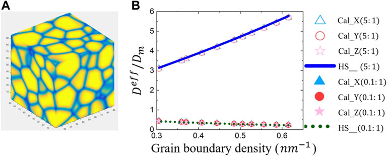
FIGURE 3. (A) The simulated isometric polycrystalline microstructure. Blue lines are grain boundaries and the yellow parts are grains. (B) Comparison between the simulated and analytical effective diffusion coefficients as a function of the grain boundary density alone three different directions with diffusion coefficient ratios of H in the grain boundary to that in matrix phase are 0.1:1.0 and 5.0:1.0.
Based on the above three testing examples, we validate our simulation code for calculating the effective diffusion coefficients in different structures.
3.2 Effective Diffusion Coefficient of H in Polycrystalline W
Based on our validated simulation code, we first study the effective diffusion coefficient of H in the polycrystalline W. The polycrystalline structures are generated using the phase-field model by solving Eqs 1–4. Three different polycrystalline structures including an isotropic grain structure and two columnar grain structures with different grain sizes are constructed as shown in Figures 4A–C. Then the effective diffusion coefficients of H in these three different polycrystalline structures can be obtained by solving Eq. 16.
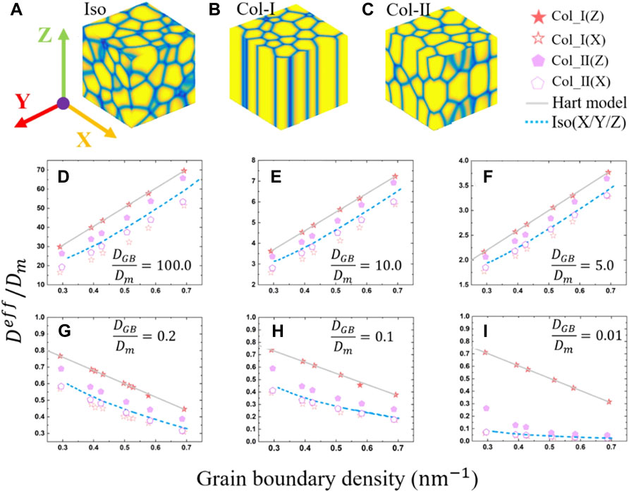
FIGURE 4. Polycrystalline structure of the (A) isometric crystal, (B) columnar-I crystal, and (C) columnar-II crystal. The calculated effective diffusion coefficients for three different polycrystalline structures with three diffusion coefficient ratios
The diffusion coefficient
According to previous atomic simulation results, the H diffusivity in the grain boundary can be either larger or smaller than that in the bulk, depending on the grain boundary type (Yu et al., 2014; Zhou et al., 2019B). To systematically investigate the effect of the grain boundary on the H diffusion in the polycrystalline W, six different ratios
Figure 4 shows the comparison of the numerically simulated and analytically calculated effective diffusion coefficients as a function of the grain boundary density in three polycrystalline structures. Figures 4D–F are for the case of
2D simulations can save lots of computational resources compared to 3D simulations. We also calculate the effective diffusion coefficient of H in isometric structures in 2D. At the same grain boundary density, the effective diffusion coefficients in 2D are usually smaller than that in 3D. Next, we derive a correlation that transfers the 2D effective diffusion coefficient into 3D based on Bakker et al.‘s derivations, in which two formulas depending on the ratio of the diffusivity in the grain boundary and bulk that can transfer the 2D thermal conductivity into 3D were given (Bakker et al., 1995). When the H diffusion coefficient
where
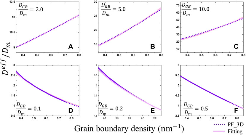
FIGURE 5. The comparison between the simulated and fitted effective diffusion coefficients of H in 3D polycrystalline W with three diffusion coefficient ratios DGB/Dm of H are greater than 1.0 (A-C) and less than 1.0 (D-F). The fitted 3D data is calculated from the 2D results by using Eqs 30, 31. The purple dotted curves represent the simulated results and the pink solid curves represent the results predicted by the fitting formula.
For the H diffusion coefficient
where
3.3 Effective Diffusion Coefficient of H in Porous Single Crystalline W
In addition to grain boundaries, irradiation-induced vacancies and their clusters can also affect the diffusion of H atoms (Wang et al., 2019). The porous structures formed by clustering of vacancies are generated by phase-field simulations through solving Eqs 5–15. Based on the phase-field simulated porous single crystalline W microstructures, we then study the effect of the porosity on the effective diffusion coefficient of H.
The diffusion tensor in the void and the matrix can be expressed as
where
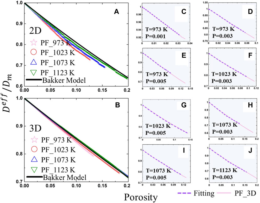
FIGURE 6. The simulated and analytical effective diffusion coefficients as a function of the porosity for four different temperatures in 2D (A) and 3D (B). (C)–(J) Comparison between the simulated and fitted effective diffusion coefficients of H in 3D porous W as a function of the temperature and porosity, in which the pink solid curves represent the simulation results and the purple dotted curves represent the results predicted by Eq. 39 based on 2D results.
Both the 2D and 3D effective diffusion coefficients of H as a function of the temperature and porosity in the porous single crystalline W are calculated. To obtain a general correlation that can transfer the 2D effective diffusion coefficient into the 3D in porous materials, we use the 2D and 3D calculated results to fit the parameter A by using the Eq. 39 proposed by Bakker et al. (Bakker et al., 1995),
where p,
3.4 Effective Diffusion Coefficient of H in Porous Polycrystalline W
We study the effective diffusion coefficient of H during the formation of voids in two different polycrystalline W as a function of the porosity. We take a particular temperature of 1073 K for an example. The polycrystalline microstructures are generated using phase-field simulations by solving Eqs 1–4. The nucleation and growth of voids are simulated by solving Eqs 5–15. It is simply assumed that the grain structures don’t evolve with the time during the formation of voids, and the same scenario was used in other relevant work (Wang et al., 2018). The simulated microstructures of the porous polycrystalline W at 0.001 s are shown in Figure 7C, where the solid lines represent the grain boundaries and the solid red round areas represent the voids. We assume the grain boundary is a perfect sink for vacancies, which is consistent with the experimental observations (Klimenkov et al., 2016).
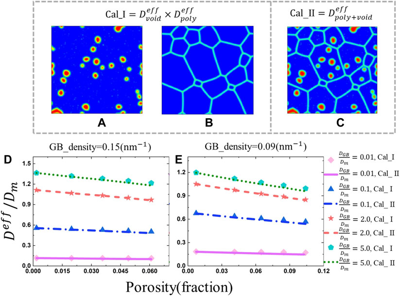
FIGURE 7. Microstructure used for the first method (A, B) and second method (C) for calculating the effective diffusion coefficient. Comparison of the value
The simulated microstructure is divided into three separate phases including the matrix, grain boundary, and void phases. We use two different methods to calculate the effective diffusion coefficient of H in this three-phase system. Firstly, we calculate the effective diffusion coefficient of H in the polycrystalline structure and porous structure separately as shown in Figures 7A,B. For the polycrystalline structure part, the solution process is the same as that in section 3.2, while for the effect of the porosity on the diffusion of H, the solution process is the same as that in section 3.3. The overall effective diffusion coefficient of H in the three-phase structure is assumed to be a product of the effective diffusion coefficient of the polycrystalline system
Secondly, the effective diffusion coefficients of H can be calculated directly from the three-phase structure by solving Eq. 16 as shown in Figure 7C. The diffusion coefficient in each phase can be described in section as Eq. 17.
Figures 7D, E show the effective diffusion coefficients as a function of the porosity for different diffusion coefficient ratios obtained by above two different means, in which the scatter points represent the results obtained by the first approach that are calculated by multiplying the results of two separate systems as shown in Eq. 40, and the curves represent the results derived from the second method that are directly calculated according to the three-phase system. Two different grain boundary densities of 0.15 nm−1 and 0.09 nm−1 are considered. Results show that the effective diffusion coefficient decreases with the increase of the porosity. In the case of
Based on the above 2D results, the effective diffusion coefficient of H in a 3D porous polycrystalline W can be predicted by using Eqs. 35, 37, 39. The predicted effective diffusion coefficients of H in the 3D porous polycrystalline W as a function of the porosity are shown in Figure 8. Results show that the effective diffusion coefficient decreases with the increase of the porosity, which has the same trend as that in 2D. The effective diffusion coefficient decreases with the increase of the grain boundary density for the case of
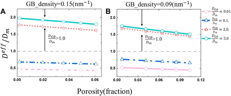
FIGURE 8. Predicted values of
4 Conclusion
We propose a numerical method to systemically study the effective diffusion coefficients of hydrogen (H) atoms in the porous polycrystalline tungsten (W). We assume the H atoms can be eventually desorbed from the grain boundaries and voids once they were trapped, which is based on thermal desorption experimental results (Eleveld and Veen, 1994; Hodille et al., 2017). The grain structure and irradiated voids are generated by using phase-field simulations. The effective diffusion coefficient in such an inhomogeneous system is obtained by solving the steady-state diffusion equation with a spectral iterative algorithm. The effects of the grain morphology, porosity, and their synergistic effect on the effective diffusion coefficient of H in W are systemically investigated. Our main research findings from the above simulations can be summarized as follows.
1) Using a spectral iterative algorithm, the calculated effective diffusion coefficients of three simple microstructures agree well with those predicted by previous analytical models, which fully validates our simulation code.
2) In the polycrystalline W, when the grain boundary density is a constant, the effective diffusion coefficient of H is always greater in columnar crystals than that in isometric crystals along the elongated grain direction, regardless of whether the diffusion coefficient in the grain boundary is larger or smaller than that in the bulk.
3) For the porous W, the effective diffusion coefficient of H significantly decreases with the increase of the porosity. When the porosity is a constant, our simulation results show that the effective diffusion coefficient increases with the increase of the average size of voids.
4) Based on our simulated effective diffusion coefficients in polycrystalline and porous W, two correlations that can transfer the two-dimensional (2D) effective diffusion coefficient into three-dimensional (3D) are fitted. Using these fitted correlations, we predict the effective diffusion coefficient of H in the 3D porous polycrystalline W based on 2D results, which can greatly save computational resources. It is found that the effective diffusion coefficient of H in a heterogeneous system is equal to the product of the effective diffusion coefficient of H in each phase.
The present study can help to better understand the influence of the grain boundary and void evolutions on the H diffusion in W. Other defect structures such as gas bubbles, dislocations, and precipitates influence the H diffusion can also be easily included in the model. It is also worthy to point out that the experimental observations can be used as input microstructures instead of the phase-field simulated microstructures to calculate the effective diffusion coefficient of H. We expect that our findings can provide some references on how to control the H and its isotope retention and for the design of W-based materials fusion devices in the future. The current method can also be used in other systems that the diffusion component is not trapped by the microstructures.
Data Availability Statement
The original contributions presented in this study are included in the article. The raw/processed data required to reproduce these findings cannot be shared at this time as the data also forms part of an ongoing study.
Author Contributions
BL performed the numerical simulations, produced the figures, conducted analysis, and wrote the draft of the manuscript. JH, BX, SJ, H-BZ, and LL made substantial contributions to the analysis of the simulation results. LL and G-HL proposed the idea, revised it critically for important intellectual content, and approved the final version to be published. All authors contributed to the article and approved the submitted version.
Funding
This research is supported by the National Natural Science Foundation of China with Grant Nos 12075021, 12075023, and 51720105006, and the National MCF Energy R&D Program of China with Grant No. 2018YFE0308103.
Conflict of Interest
The authors declare that the research was conducted in the absence of any commercial or financial relationships that could be construed as a potential conflict of interest.
Publisher’s Note
All claims expressed in this article are solely those of the authors and do not necessarily represent those of their affiliated organizations, or those of the publisher, the editors and the reviewers. Any product that may be evaluated in this article, or claim that may be made by its manufacturer, is not guaranteed or endorsed by the publisher.
References
Aagesen, L. K., Biswas, S., Jiang, W., Andersson, D., Cooper, M. W. D., and Matthews, C. (2021). Phase-field Simulations of Fission Gas Bubbles in High Burnup UO2 during Steady-State and LOCA Transient Conditions. J. Nucl. Mater. 557, 153267. doi:10.1016/j.jnucmat.2021.153267
Allen, S. M., and Cahn, J. W. (1973). A Correction to the Ground State of Fcc Binary Ordered Alloys with First and Second Neighbor Pairwise Interactions. Scr. Metall. 7, 1261–1264. doi:10.1016/0036-9748(73)90073-2
Allen, S. M., and Cahn, J. W. (1972). Ground State Structures in Ordered Binary Alloys with Second Neighbor Interactions. Acta Metall. 20, 423–433. doi:10.1016/0001-6160(72)90037-5
Artsimovich, L. A. (1972). Tokamak Devices. Nucl. Fusion 12, 215–252. doi:10.1088/0029-5515/12/2/012
Bakker, K., Kwast, H., and Cordfunke, E. H. P. (1995). Determination of a Porosity Correction Factor for the Thermal Conductivity of Irradiated U02 Fuel by Means of the Finite Element Method. J. Nucl. Mater. 226, 128–143. doi:10.1016/0022-3115(95)00087-9
Bolt, H., Barabash, V., Krauss, W., Linke, J., Neu, R., Suzuki, S., et al. (2004). Materials for the Plasma-Facing Components of Fusion Reactors. J. Nucl. Mater. 329-333, 66–73. doi:10.1016/j.jnucmat.2004.04.005
Cahn, J. W., and Hilliard, J. E. (1958). Free Energy of a Nonuniform System. I. Interfacial Free Energy. J. Chem. Phys. 28, 258–267. doi:10.1063/1.1744102
Cahn, J. W. (1961). On Spinodal Decomposition. Acta Metall. 9, 795–801. doi:10.1016/0001-6160(61)90182-1
Chen, L.-Q., Yang, W., et al. (1994). Computer Simulation of the Domain Dynamics of a Quenched System with a Large Number of Nonconserved Order Parameters: The Grain-Growth Kinetics. Phys. Rev. B 50, 15752–15756. doi:10.1103/physrevb.50.15752
Chen, L. Q., and Shen, J. (1998). Applications of Semi-implicit Fourier-Spectral Method to Phase Field Equations. Comput. Phys. Commun. 108, 147–158. doi:10.1016/s0010-4655(97)00115-x
Chen, Y., and Schuh, C. A. (2007). Geometric Considerations for Diffusion in Polycrystalline Solids. J. Appl. Phys. 101, 063524. doi:10.1063/1.2711820
Cottrell, G. A. (2004). Sigma Phase Formation in Irradiated Tungsten, Tantalum and Molybdenum in a Fusion Power Plant. J. Nucl. Mat. 334, 66–68. doi:10.1016/j.jnucmat.2004.07.001
El-Kharbachi, A., Chêne, J., Garcia-Argote, S., Marchetti, L., Martin, F., Miserque, F., et al. (2014). Tritium Absorption/desorption in ITER-like Tungsten Particles. Int. J. Hydrogen Energy 39, 10525–10536. doi:10.1016/j.ijhydene.2014.05.023
Eleveld, H., and van Veen, A. (1994). Void Growth and Thermal Desorption of Deuterium from Voids in Tungsten. J. Nucl. Mater. 212-215, 1421–1425. doi:10.1016/0022-3115(94)91062-6
Fan, D., and Chen, L.-Q. (1997). Computer Simulation of Grain Growth Using a Continuum Field Model. Acta Mater. 45, 611–622. doi:10.1016/s1359-6454(96)00200-5
Frauenfelder, R. (1969). Solution and Diffusion of Hydrogen in Tungsten. J. Vac. Sci. Technol. 6, 388–397. doi:10.1116/1.1492699
Fu, B., Qiu, M., Cui, J., Wang, J., and Hou, Q. (2021). Diffusion, Trapping, and Dissociation Behaviours of Helium at the Σ5 Grain Boundary in Tungsten: A Molecular Dynamics Study. J. Nucl. Mater. 543, 152599. doi:10.1016/j.jnucmat.2020.152599
Fujita, H., Uemura, Y., Sakurada, S., Azuma, K., Zhou, Q., Toyama, T., et al. (2017). The Damage Depth Profile Effect on Hydrogen Isotope Retention Behavior in Heavy Ion Irradiated Tungsten. Fusion Eng. Des. 125, 468–472. doi:10.1016/j.fusengdes.2017.05.141
González, C., Panizo-Laiz, M., Gordillo, N., et al. (2015). H Trapping and Mobility in Nanostructured Tungsten Grain Boundaries: a Combined Experimental and Theoretical Approach Nucl. Fusion 55, 113009. doi:10.1088/0029-5515/55/1/113009
Grisolia, C., Hodille, E., Chene, J., Garcia-Argote, S., Pieters, G., El-Kharbachi, A., et al. (2015). Tritium Absorption and Desorption in ITER Relevant Materials: Comparative Study of Tungsten Dust and Massive Samples. J. Nucl. Mater. 463, 885–888. doi:10.1016/j.jnucmat.2014.10.089
Guo, W., Cheng, L., De Temmerman, G., Yuan, Y., and Lu, G.-H. (2018). Retarded Recrystallization of Helium-Exposed Tungsten. Nucl. Fusion 58, 106011. doi:10.1088/1741-4326/aad2b0
Hao, J., Jin, S., Lu, G.-H., and Xu, H. (2020). Migration Energy Barriers and Diffusion Anisotropy of Point Defects on Tungsten Surfaces. Comput. Mater. Sci. 184, 109893. doi:10.1016/j.commatsci.2020.109893
Hart, E. W. (1957). On the Role of Dislocations in Bulk Diffusion. Acta Metall. 5, 597–605. doi:10.1016/0001-6160(57)90127-x
Hasegawa, A., Fukuda, M., Nogami, S., and Yabuuchi, K. (2014). Neutron Irradiation Effects on Tungsten Materials. Fusion Eng. Des. 89, 1568–1572. doi:10.1016/j.fusengdes.2014.04.035
Hasegawa, A., Fukuda, M., Yabuuchi, K., et al. (2016). Neutron Irradiation Effects on the Microstructural Development of Tungsten and Tungsten Alloys. J. Nucl. Mat. 471175-183. doi:10.1016/j.jnucmat.2015.10.047
Heinola, K., and Ahlgren, T. (2010a). Diffusion of Hydrogen in Bcc Tungsten Studied with First Principle Calculations. J. Appl. Phys. 107, 113531. doi:10.1063/1.3386515
Heinola, K., and Ahlgren, T. (2010b). First-principles Study of H on the Reconstructed W (100) Surface. Phys. Rev. B 81, 073409. doi:10.1103/physrevb.81.073409
Hodille, E. A., Begrambekov, L. B., Pascal, J. Y., Saidi, O., Layet, J. M., Pégourié, B., et al. (2014). Hydrogen Trapping in Carbon Film: From Laboratories Studies to Tokamak Applications. Int. J. Hydrogen Energy 39, 20054–20061. doi:10.1016/j.ijhydene.2014.09.027
Hodille, E. A., Ghiorghiu, F., Addab, Y., Založnik, A., Minissale, M., Piazza, Z., et al. (2017). Retention and Release of Hydrogen Isotopes in Tungsten Plasma-Facing Components: the Role of Grain Boundaries and the Native Oxide Layer from a Joint Experiment-Simulation Integrated Approach. Nucl. Fusion 57, 076019. doi:10.1088/1741-4326/aa6d24
Hu, X., Koyanagi, T., Fukuda, M., Kumar, N. A. P. K., Snead, L. L., Wirth, B. D., et al. (2016). Irradiation Hardening of Pure Tungsten Exposed to Neutron Irradiation. J. Nucl. Mater. 480, 235–243. doi:10.1016/j.jnucmat.2016.08.024
Jiang, C., Ke, J. H., Simon, P. C. A., et al. (2021). Atomistic and Mesoscale Simulations to Determine Effective Diffusion Coefficient of Fission Products in SiC. Idaho National Lab. (INL), Idaho Falls, ID (United States) https://www.osti.gov/servlets/purl/1825508.
Jin, Y., Roh, K.-B., Sheen, M.-H., Kim, N.-K., Song, J., Kim, Y.-W., et al. (2017). Enhancement of Deuterium Retention in Damaged Tungsten by Plasma-Induced Defect Clustering. Nucl. Fusion 57, 126042. doi:10.1088/1741-4326/aa856c
Johnson, D. F., and Carter, E. A. (2010). Hydrogen in Tungsten: Absorption, Diffusion, Vacancy Trapping, and Decohesion. J. Mat. Res. 25, 315–327. doi:10.1557/jmr.2010.0036
Kim, S. G. (2007). A Phase-Field Model with Antitrapping Current for Multicomponent Alloys with Arbitrary Thermodynamic Properties. Acta Mater. 55, 4391–4399. doi:10.1016/j.actamat.2007.04.004
Kim, S. G., Kim, W. T., and Suzuki, T. (1999). Phase-field Model for Binary Alloys. Phys. Rev. E 60, 7186–7197. doi:10.1103/physreve.60.7186
Kimizuka, H., and Ogata, S. (2011). Slow Diffusion of Hydrogen at a Screw Dislocation Core Inα-Iron. Phys. Rev. B 84, 024116. doi:10.1103/physrevb.84.024116
Klimenkov, M., Jäntsch, U., Rieth, M., Schneider, H. C., Armstrong, D. E. J., Gibson, J., et al. (2016). Effect of Neutron Irradiation on the Microstructure of Tungsten. Nucl. Mater. Energy 9, 480–483. doi:10.1016/j.nme.2016.09.010
Krill III, C. E., and Chen, L.-Q. (2002). Computer Simulation of 3-D Grain Growth Using a Phase-Field Model. Acta Mater. 50, 3059–3075. doi:10.1016/s1359-6454(02)00084-8
L. Briant, C., and Walter, J. L. (1988). Void Growth in Tungsten Wire. Acta Metall. 36, 2503–2514. doi:10.1016/0001-6160(88)90196-4
Li, B., Jin, S., Xue, B., Liang, L., and Lu, G.-H. (2022). Phase-field Microstructure-Based Effective Thermal Conductivity Calculations in Tungsten. Nucl. Fusion 62, 076041. doi:10.1088/1741-4326/ac6284
Li, Y.-H., Zhou, H.-B., Jin, S., Zhang, Y., Deng, H., and Lu, G.-H. (2017). Behaviors of Transmutation Elements Re and Os and Their Effects on Energetics and Clustering of Vacancy and Self-Interstitial Atoms in W. Nucl. Fusion 57, 046006. doi:10.1088/1741-4326/aa5893
Li, Y., Hu, S., Sun, X., Gao, F., Henager, C. H., and Khaleel, M. (2011). Phase-field Modeling of Void Evolution and Swelling in Materials under Irradiation. Sci. China Phys. Mech. Astron. 54, 856–865. doi:10.1007/s11433-011-4316-y
Liu, Y.-L., Zhang, Y., Zhou, H.-B., Lu, G.-H., Liu, F., and Luo, G.-N. (2009). Vacancy Trapping Mechanism for Hydrogen Bubble Formation in Metal. Phys. Rev. B 79, 172103. doi:10.1103/physrevb.79.172103
Liu, Y.-N., Wu, T., Yu, Y., Li, X.-C., Shu, X., and Lu, G.-H. (2014). Hydrogen Diffusion in Tungsten: A Molecular Dynamics Study. J. Nucl. Mater. 455, 676–680. doi:10.1016/j.jnucmat.2014.09.003
Louthan, M. R., Caskey, G. R., Donovan, J. A., and Rawl, D. E. (1972). Hydrogen Embrittlement of Metals. Mater. Sci. Eng. 10, 357–368. doi:10.1016/0025-5416(72)90109-7
Mannheim, A., Van Dommelen, J. A. W., and Geers, M. G. D. (2018). Modelling Recrystallization and Grain Growth of Tungsten Induced by Neutron Displacement Defects. Mech. Mater. 123, 43–58. doi:10.1016/j.mechmat.2018.04.008
Maxwell, J. C. A. (1881). Treatise on Electricity and Magnetism: Pt. III. Magnetism. Pt. IV. Electromagnetism. Clarendon Press.
Millett, P. C., Rokkam, S., El-Azab, A., Tonks, M., and Wolf, D. (2009). Void Nucleation and Growth in Irradiated Polycrystalline Metals: a Phase-Field Model. Model. Simul. Mat. Sci. Eng. 17, 064003. doi:10.1088/0965-0393/17/6/064003
Moelans, N., Blanpain, B., and Wollants, P. (2008). Quantitative Analysis of Grain Boundary Properties in a Generalized Phase Field Model for Grain Growth in Anisotropic Systems. Phys. Rev. B 78, 024113. doi:10.1103/physrevb.78.024113
Moradi, A. (2015). Maxwell-Garnett Effective Medium Theory: Quantum Nonlocal Effects. Phys. Plasmas 22, 042105. doi:10.1063/1.4917252
Oudriss, A., Creus, J., Bouhattate, J., Conforto, E., Berziou, C., Savall, C., et al. (2012). Grain Size and Grain-Boundary Effects on Diffusion and Trapping of Hydrogen in Pure Nickel. Acta Mater. 60, 6814–6828. doi:10.1016/j.actamat.2012.09.004
Rasch, K.-D., Siegel, R. W., and Schultz, H. (1980). Quenching and Recovery Investigations of Vacancies in Tungsten. Philos. Mag. A 41, 91–117. doi:10.1080/01418618008241833
Ratanaphan, S., Boonkird, T., Sarochawikasit, R., Beladi, H., Barmak, K., and Rohrer, G. S. (2017). Atomistic Simulations of Grain Boundary Energies in Tungsten. Mater. Lett. 186, 116–118. doi:10.1016/j.matlet.2016.09.104
Rieth, M., Doerner, R., Hasegawa, A., Ueda, Y., and Wirtz, M. (2019). Behavior of Tungsten under Irradiation and Plasma Interaction. J. Nucl. Mater. 519, 334–368. doi:10.1016/j.jnucmat.2019.03.035
Sakurada, S., Uemura, Y., Fujita, H., Azuma, K., Toyama, T., Yoshida, N., et al. (2017). Impact of Annealing on Deuterium Retention Behavior in Damaged W. Fusion Sci. Technol. 72, 785–788. doi:10.1080/15361055.2017.1350480
Stepper, H.-J. (1972). Recrystallization of α Particle Irradiated Tungsten. Mt 3, 2293–2294. doi:10.1007/bf02643247
Taketomi, S., Matsumoto, R., and Miyazaki, N. (2008). Atomistic Study of Hydrogen Distribution and Diffusion Around a {112} Edge Dislocation in Alpha Iron. Acta Mater. 56, 3761–3769. doi:10.1016/j.actamat.2008.04.011
Ueda, Y., Funabiki, T., Shimada, T., Fukumoto, K., Kurishita, H., and Nishikawa, M. (2005). Hydrogen Blister Formation and Cracking Behavior for Various Tungsten Materials. J. Nucl. Mater. 337-339, 1010–1014. doi:10.1016/j.jnucmat.2004.10.077
Vaidya, W. V., and Ehrlich, K. (1983). Radiation-Induced Recrystallization, its Cause and Consequences in Heavy-Ion Irradiated 20% Cold-Drawn Steels of Type 1.4970. J. Nucl. Mat. 113, 149–162. doi:10.1016/0022-3115(83)90137-X
Wang, H., Biswas, S., Han, Y., and Tomar, V. (2018). A Phase Field Modeling Based Study of Microstructure Evolution and its Influence on Thermal Conductivity in Polycrystalline Tungsten under Irradiation. Comput. Mater. Sci. 150, 169–179. doi:10.1016/j.commatsci.2018.03.070
Wang, J.-J., Wang, Y., Ihlefeld, J. F., Hopkins, P. E., and Chen, L.-Q. (2016). Tunable Thermal Conductivity via Domain Structure Engineering in Ferroelectric Thin Films: A Phase-Field Simulation. Acta Mater. 111, 220–231. doi:10.1016/j.actamat.2016.03.069
Wang, L. F., Shu, X., Lin, D. Y., et al. (2019). Molecular Dynamics Studies of Hydrogen Diffusion in Tungsten at Elevated Temperature: Concentration Dependence and Defect Effects. Int. J. Hydrogen Energy 45, 822–834. doi:10.1016/j.ijhydene.2019.10.151
Xue, Y., and Hassanein, A. (2014). Kinetic Monte Carlo Simulation of Hydrogen Diffusion on Tungsten Reconstructed (0 0 1) Surface. Fusion Eng. Des. 89, 2545–2549. doi:10.1016/-j.fusengdes.2014.06.001
Yang, L., and Wirth, B. D. (2019). First-principles Study of Hydrogen Diffusion and Self-Clustering below Tungsten Surfaces. J. Appl. Phys. 125, 1651051–2165105.14. doi:10.1063/1.5092595
Yang, X., and Oyeniyi, W. O. (2017). Kinetic Monte Carlo Simulation of Hydrogen Diffusion in Tungsten. Fusion Eng. Des. 114, 113–117. doi:10.1016/j.fusengdes.2016.12.012
Yu, Y., Shu, X., Liu, Y.-N., and Lu, G.-H. (2014). Molecular Dynamics Simulation of Hydrogen Dissolution and Diffusion in a Tungsten Grain Boundary. J. Nucl. Mater. 455, 91–95. doi:10.1016/j.jnucmat.2014.04.016
Zhou, H., Yu, J., Chen, C., and Zhu, K. (2019a). Effect of Pre-damage Induced by Argon Ions on the Deuterium Blister Formation in Tungsten-Tantalum Alloys Exposed to Deuterium Plasma. Int. J. Hydrogen Energy 44, 23320–23329. doi:10.1016/j.ijhydene.2019.07.061
Keywords: phase-field, microstructure evolution, effective diffusion coefficient, hydrogen, tungsten
Citation: Li B, Xue B, Hao J, Jin S, Zhou H-B, Liang L and Lu G-H (2022) The Effective Diffusion Coefficient of Hydrogen in Tungsten: Effects of Microstructures From Phase-Field Simulations. Front. Mater. 9:935129. doi: 10.3389/fmats.2022.935129
Received: 03 May 2022; Accepted: 30 May 2022;
Published: 30 June 2022.
Edited by:
Yu-Hong Zhao, North University of China, ChinaReviewed by:
Yongxin Wang, Northwestern Polytechnical University, ChinaChunguang Yang, Institute of Metal Research (CAS), China
Yong Ni, University of Science and Technology of China, China
Copyright © 2022 Li, Xue, Hao, Jin, Zhou, Liang and Lu. This is an open-access article distributed under the terms of the Creative Commons Attribution License (CC BY). The use, distribution or reproduction in other forums is permitted, provided the original author(s) and the copyright owner(s) are credited and that the original publication in this journal is cited, in accordance with accepted academic practice. No use, distribution or reproduction is permitted which does not comply with these terms.
*Correspondence: Linyun Liang, bHlsaWFuZ0BidWFhLmVkdS5jbg==; Guang-Hong Lu, bGdoQGJ1YWEuZWR1LmNu
 Bingchen Li
 Bowen Xue1,2
 Linyun Liang