 Xuli Zhu
 Shanshan Ma
 Dong Dong1
 Guirong Teng
- 1School of Mechanical and Electronic Engineering, Shandong University of Science and Technology, Qingdao, China
- 2School of Energy and Mining Engineering, Shandong University of Science and Technology, Qingdao, China
Magnetorheological transmission devices (MRTDs) are a type of power transmission device using magnetorheological fluids (MRFs) as the transmission medium, which have the advantages of rapid response and continuously adjustable output performances. A new type of structure of planetary MRTDs is proposed to improve the performances of MRTDs in this study. A planetary MRTD was fabricated, and the performances of it were tested on the self-made testing system. The experimental results show that the continuously variable transmission of MRTDs under constant torque can be realized by adjusting the excitation current. The output speed or torque can be adjusted by adjusting the control current when the input speed is constant. The output torque increases with the increase in the input speed when the excitation current is constant. The performances of the MRTD were analyzed according to the properties of MRFs in complex flow and magnetic field. MRFs in complex flow and magnetic fields can produce more stable and higher responses to external magnetic fields than being simple sheared; thus, the planetary MRTDs have better performances and are useful structures for the application of MRFs in transmission.
Introduction
The development of intelligent mechanical equipment has gradually increased the requirements for the transmission performance of transmission devices, especially in the controllability of torque and speed. The controllability of the apparent viscosity of smart fluids provides the possibility to realize performance-controllable mechanical transmission by controlling the external fields. As a kind of smart material, magnetorheological fluids (MRFs) are suspensions of micron-size magnetizable particles in a viscous matrix fluid enriched with additives. Under the action of an applied magnetic field, an MRF transforms from a viscous fluid to a solid-like state, and its physical properties (e.g., mechanical, electromagnetic, and thermal properties) change simultaneously, which is called the magnetorheological effect. The magnetorheological effect has the advantages of being continuously controllable, fast, and reversible (Ashtiani, et al., 2015; Kumar, et al., 2019) and makes MRFs show a strong potential for applications in the field of transmission control.
Magnetorheological transmission devices (MRTDs) are a new type of transmission device that use MRFs as the power transmission medium and utilizes the magnetorheological effect for transmission control. MRTDs can change the shearing state of MRFs between transmission interfaces by adjusting the external magnetic field and then control the output parameters. MRTDs are convenient for controlling their real-time torque and speed during operation and have the advantages of fast response, high shock resistance, and stepless speed adjustment (Tian, et al., 2015; Wang, et al., 2018).
Güth and Maas, 2016 proposed an MRF brake based on the Taylor vortex for application in wind turbines, whose torque performance was better than that of other conventional brakes using dry friction. Wang et al. (2019) designed a high-torque squeezing magnetorheological brake and studied the squeeze strengthening effect of a silicone oil-based magnetorheological fluid with the addition of nanometer-sized Fe3O4. It was found that the braking torque showed a nearly linear increase with the increase in the squeezing stress. Sarkar and Hirani, 2013 proposed a method to apply pressure to the MRF to increase the output torque of the magnetorheological brake. A single-disc magnetorheological brake was developed, and it was found that the braking torque of the brake was higher when pressure was applied to the magnetorheological fluid than that of a brake operating only under shear. Bucchi et al. (2014) developed an auxiliary device based on MRFs for engaging and disengaging a combustion engine combined with a magneto-thermographic method. The magnetorheological clutch was allowed to operate as the main clutch. Song et al. (2021) designed a small magnetorheological brake based on a hybrid mode of shear and flow, which can provide higher torque using a relatively small amount of the magnetorheological fluid. Tian et al. (2022) studied the time response characteristics of MRTDs and found that changing the parameters of the excitation coil and the number of taps can effectively shorten the current response time. Qiu et al. (2022) used the electromagnetic force generated after the excitation coil being electrified to squeeze the magnetorheological fluid along the direction of the magnetic field and improve the shear yield stress of the magnetorheological fluid, thus greatly improving the transmission performance of the magnetorheological fluid. Moghani and Kermani, 2020 designed a lightweight magnetorheological brake using the hybrid magnetization of an electromagnetic coil and a permanent magnet, which can reduce the magnetic saturation in the magnetic circuit and reduce the volume of materials used in the magnetic circuit. The output torque performance of the composite magnetorheological clutch which was proposed by Dai et al. (2013) was enhanced over the simple disc-shearing clutches. Li et al. (2014) optimized the MRF working area inside the actuator to increase the working interface and improve the performance of the actuator. Wang (2014) analyzed the transmission characteristics under high transmission power and the temperature characteristics of MRF in the working process. It was concluded that using a water cooling system to cool the MRTD was effective and can improve the working reliability of the device. Chen (2014) developed a transmission device–combined MRF and shape memory alloy, which could compensate for the lack of MRF performance at high temperature through the driving effect of the shape memory alloy.
The development trends of MRTDs are high torque, high power, compact design, reliable operation, convenient control, wide adjustable range, etc. Now, MRTDs are gradually moving closer to practicality. Summarizing the mechanisms of MRTDs, it can be seen that the working modes of MRFs are basically simple shearing with a uniform magnetic field. These designs cannot overcome the problem of MRF shear thinning at high shear rates. The MRFs are prone to solid–liquid separation under strong centrifugal forces because transmission devices are all rotating at high speeds. For these reasons, a new structure of planetary MRTD is proposed in this study which can effectively overcome the problems of shear thinning and solid–liquid separation of MRFs. This new structure is expected to achieve controllable and stable high-power transmission.
Transmission Mechanism
Basic Mechanism
The basic conceptual mechanism of planetary MRTDs is shown in Figure 1. The inner and outer rings are used as the input and output components, respectively; several magnetic rollers are placed at the middle of the gap between the inner and outer rings, and there are clearances between the rollers and the rings, and the MRF fills the gap between rings. This transmission device is a two-degree-of-freedom planetary mechanism with the magnetic rollers taking planetary motion during transmission. The state of the MRF is controlled by the applied magnetic field to realize the adjustable power transmission between the inner and outer rings.
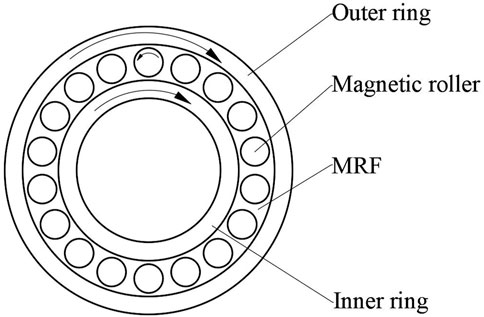
FIGURE 1. Structural diagram of a planetary MRTD.
The mechanism analysis of the planetary MRTD is shown in Figure 2. The working status parameters of the planetary MRTD are that the inner and outer rings rotate with angle speeds of ω1 and ω2, respectively, as the magnetic rollers rotate with an angle speed of ω0. The relative velocity of the surface a magnetic roller to surfaces of rings is shown by the blue arrows in the figure. Then, the working region of the MRF can be divided into four parts, where the MRF is squeezed in regions I and III and is stretched in regions II and IV. A slight shearing rate can be obtained on the surfaces of the rings and rollers by the transformation of the strain rate tensor, which can produce shear stress. The surfaces of regions I and II generate driving torque to the roller, and regions III and IV generate resistance torque. The torque acting on the roller should be balanced according to mechanical analysis. Based on the same principle, the shear stress on the inner ring surface can produce the resistance torque to the inner ring, and the shear stress on the outer ring surface can produce the driving torque to the outer ring. The shear stress of MRF is very large under the action of the magnetic field so that the transmission torque of the planetary MRTD is large. It can be seen from the aforementioned analysis that the planetary MRTD can realize large controllable torque transmission.
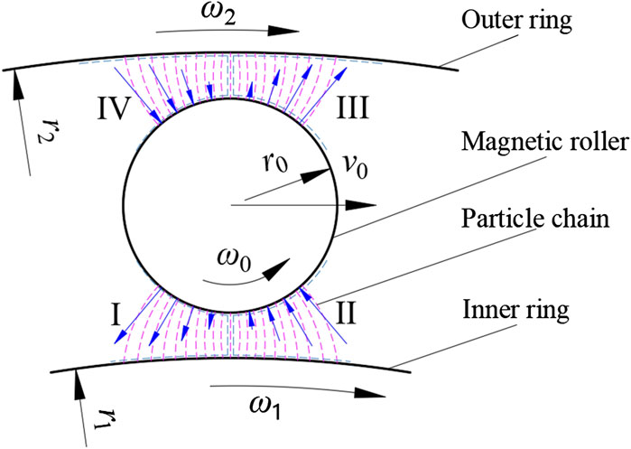
FIGURE 2. Mechanism analysis of the planetary MRTD.
Considering the actual situation of a planetary MRTD, the roller takes planetary motion, and the aforementioned rotation should be superimposed with the clockwise movement of the roller as a whole. When there is a rotation speed difference between the inner and outer rings, the working state of the MRF is squeeze shear combination or stretch shear combination. The power is transmitted from the inner ring to the outer ring due to the transmission of MRF. The higher the apparent viscosity of the MRF, the greater the power is transmitted.
The planetary MRTD makes the power transfer regions characterized by high magnetic field strength and low strain rate, which can improve the adverse effect of MRF shear thinning at high shear rates. Therefore, the rotation of the magnetic roller can realize the MRF rheological effect of extrusion enhancement to enhance its transmission ability. Moreover, due to the cyclic stirring effect of the planetary motion of multiple magnetic rollers, solid–liquid separation problems of MRF will not occur. So the planetary MRTDs can be expected to effectively overcome the problems caused by MRF shear thinning and high centrifugal force and can achieve a reliable and stable controlled transmission.
Simulation Analysis
The MRF flow inside a planetary MRTD is complex flow under a complex magnetic field. The flow field and magnetic field are all coupled problems due to the mutual influence of the magnetic field and fluid flow. These complexities lead to great difficulty in analyzing the performances of a planetary MRTD. In order to simplify the simulation, the default MRF has a constant magnetic permeability during the flow, so the magnetic field simulation and the flow field simulation can be performed independently. The finite element analysis package COMSOL Multiphysics was used to simulate the fluid flow and the magnetic field. The geometric model was simplified according to the symmetry of the planetary MRTD. The sub region surrounded by two adjacent rollers and the rings is selected for flow field simulation, which can be called the representative unit of the planetary MRTD. Speed of the rings and the rollers were used as boundary conditions. Figure 3A shows the simulation result of the flow field with certain parameters of the viscosity of the MRF. The two half-rollers and the region of the flow field were used together as the sub region for magnetic field simulation. Different magnetic scalar potentials were applied on the inner and outer rings as boundary conditions. Figure 3B shows the simulation result of the magnetic field with certain parameters of permeability of the MRF and the rollers.
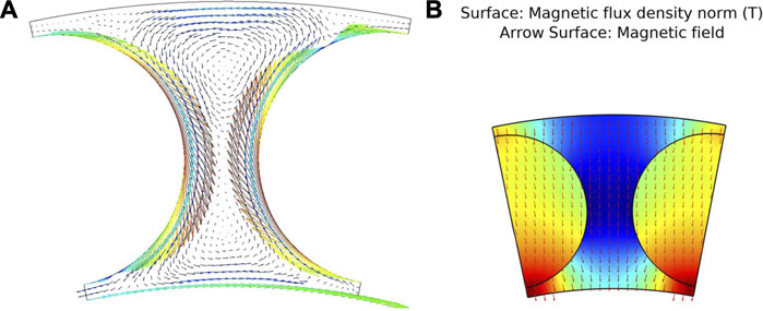
FIGURE 3. Simulation of a representative unit of a planetary MRTD. (A) Flow field simulation diagram and (B) magnetic field simulation diagram.
According to the simulation results of the flow field and magnetic field, it can be seen that the flow field and magnetic field of the MRF are all complex non-uniform fields induced by the interference of magnetic rollers. In the regions of magnetic rollers near the inner and outer rings, the magnetic field intensity is large, and the relative velocity is small. The velocity vector conforms to the analysis results in Figure 2. The magnetic field intensity near the apex of the magnetic roller near the inner ring is the largest. The regions of magnetic rollers near the inner and outer rings are the main power transmission areas. The characteristics of the flow field and magnetic field in these regions are conducive to avoiding the influence of shear thinning of MRF and enhancing the transmission torque. In the area where the rollers are close to each other, the magnetic field intensity is small but the relative velocity is large, and there are local vortices. The characteristics of the flow field and magnetic field in the region where the rollers are close to each other are helpful to prevent solid–liquid separation and enhance the uniformity and stability of the MRF.
Experiments
Experimental Prototype
The structure of the planetary MRTD is shown in Figure 4. The device mainly consists of the magnetic roller, end cap, driving shaft, driven shaft, excitation coils, magnetic sleeve, and slip ring. The driven shaft consists of driven shaft 1 and driven shaft 2. The excitation coil is assembled on the driving shaft equipped with a magnetic sleeve and connected to the power by a slip ring. The principle diagram of the planetary MRTD is shown in Figure 4A. The magnetic field lines form closed loops along the path driven shaft 1-MRF-magnetic roller-magnetic sleeve-magnetic roller-MRF-driven shaft 1. The components of the magnetic circuit are made of permeability magnetic materials, and the other components are made of non-magnetic materials. Magnetic circuit components include the magnetic sleeve, the magnetic roller, and driven shaft 1. Non-magnetic circuit components include driven shaft 2, the end cap, driving shaft, and coil skeleton. An MRF with a particle volume fraction of 25% was prepared and used to fill the gap between the inner and outer rings. The spherical carbonyl iron powder (MRF-R35, Jiangsu Tianyi Ultrafine Metal Powder Co., Ltd.) with an average diameter of 3.14 μm was used as magnetizable particles, and the dimethyl silicone oil with the viscosity of 20 centistoke was used as the matrix liquid. The main parameters of the planetary MRTD are shown in Table 1.
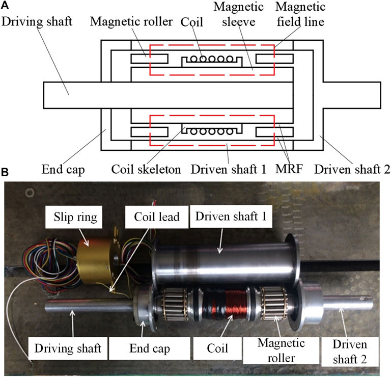
FIGURE 4. Structure of a planetary MRTD. (A) Principle diagram of the planetary MRTD and (B) image of the planetary MRTD.
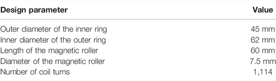
TABLE 1. Main parameters of the planetary MRTD.
The planetary MRTD designed in this study can form a working magnetic field along the radial direction of the transmission device after the excitation coil is connected to the power. The magnetic field lines pass through the MRF and the magnetic rollers. The MRF is magnetized under the action of the magnetic field and forms particle structures to resist relative movement and deformation. The output speed and torque of planetary MRTDs can be controlled by adjusting the excitation current of the coil. The complex magnetic field and flow field formed by the magnetic roller improve the ability of the MRF to transmit torque.
Experimental Platform
The experimental platform is mainly composed of the mechanical transmission system, measuring system, and control system, as shown in Figure 5. The transmission system includes an AC motor, two torque sensors, and a magnetic powder brake. The control system includes a frequency converter to control the speed of the motor; a controllable 24 V conversion DC power was used as the excitation source for the coil, and the experimental data were input to the computer through an acquisition card. The measuring system connects the sensors and the controller to measure values of speed and torque and input the measuring data to the computer. It was measured that the maximum of the excitation current for the coil of the planetary MRTD prototype was 2.7A.

FIGURE 5. Experimental system. (A) Functional component diagram and (B) image of the experimental system.
Experiments
The planetary MRTD was tested at room temperature in our laboratory, and the temperature was 20–25°C. In order to reduce the influence of the device heating on the results during the experiments, the device was cooled naturally for half an hour after each experiment. In order to test the speed control performance of the planetary MRTD at constant output torque, the braking torque of the magnetic powder brake was set to 4
To test the torque control performance of the planetary MRTD, the output shaft of the MRTD was fixed. The input speed of the planetary MRTD was adjusted from 200 r/min to 500 r/min with a step of 50 r/min. The excitation current of the electromagnetic coil was adjusted from 0 to 2A with a step of 0.5A. The frequency of the data acquisition card was set to 10 Hz. The data were input into the computer and were converted to torque values.
Results and Discussion
Speed Control Performance
The results of the speed control performance of the planetary MRTD are shown in Figure 6. The output speed of the planetary MRTD can be adjusted continuously by adjusting the excitation current when the input speed is constant. When the excitation current is small, the output speed of the device is zero due to the low magnetic field strength inside the MRF transmission region; at that magnetic field strength, the torque generated by the planetary MRTD is smaller than the braking torque applied. When the input speed is 300, 400, and 500 r/min, the initial current required to start the output of planetary MRTD is 0.55, 0.35, and 0.2A, respectively. The output speed is linear with the excitation current in a certain current range. When the input speed is 300r/min, 400r/min, and 500r/min, the linear variation ranges of the output speed are 0.6–1.2A, 0.35–0.7A, and 0.2–0.5A, respectively. The higher the input speed, the lower is the current required for the planetary MRTD to reach the initial torque and the faster the output speed increases. The reason is that the deformation rate in the MRF transmission region is larger when the input speed is higher, and a certain increment of the current can produce a larger change of the output speed. When the excitation current reaches a certain large value, the output speed remains a constant value, and the slip ratio between the inner and outer rings remains basically constant. The particle volume fraction of the MRF and the maximum excitation current are all relatively low in the experiments so that the magnetic saturation of the MRF is not obvious, and the dependence of output speed on excitation current is basically linear.
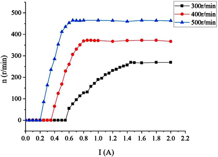
FIGURE 6. Dependence of output speed on the excitation current.
Torque Control Performance
The torque control performance of the planetary MRTD is shown in Figure 7. The output torque of the planetary MRTD is greatly improved when there is a current passed through the coil compared to when no current is present. The output torque increases with the increase in the motor speed when the excitation current is constant. The dependence of the output torque on speed is basically linear, which means that the MRF shear thinning does not occur. When the speed changes from 200r/min to 500r/min, the increment of the output torque of the planetary MRTD increases from 2.5
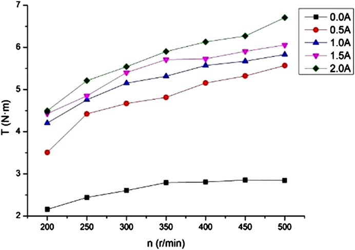
FIGURE 7. Dependence of torque on the input speed.
Conclusion
The structure of the planetary MRTD was proposed. A prototype of the planetary MRTD was designed and fabricated. The transmission mechanism of the planetary MRTD was analyzed basically. The performances of speed and torque control of the planetary MRTD were tested using the self-made experimental platform. The results were analyzed, and the main conclusions are as follows:
1) The MRF transmission regions have the characteristics of low shear rate and high magnetic field, which can effectively overcome the MRF shear thinning and solid–liquid separation problems and enhance the MRF performance.
2) The continuously output speed control of the planetary MRTD can be obtained by adjusting the excitation current of the electromagnetic coil. The larger the excitation current, the higher rotation speed can be output.
3) The continuously output torque control of the planetary MRTD can be obtained by adjusting either the excitation current of the electromagnetic coil or the input speed of the device. The larger the excitation current or higher the input speed, the larger torque can be transmitted .
Data Availability Statement
The original contributions presented in the study are included in the article/Supplementary Material; further inquiries can be directed to the corresponding author.
Author Contributions
XZ and GT conceptualized the idea. XZ and SM performed the methodology. SM and LL ran the software. SM, DD, KZ, and LL performed the experiment. SM, DD, KZ, and LL wrote the original draft. All authors have read and agreed to the published version of the manuscript.
Funding
The research of this study is supported by the National Natural Science Foundation of China, grant number 51575323.
Conflict of Interest
The authors declare that the research was conducted in the absence of any commercial or financial relationships that could be construed as a potential conflict of interest.
Publisher’s Note
All claims expressed in this article are solely those of the authors and do not necessarily represent those of their affiliated organizations, or those of the publisher, the editors, and the reviewers. Any product that may be evaluated in this article, or claim that may be made by its manufacturer, is not guaranteed or endorsed by the publisher.
Acknowledgments
The authors would like to thank the research grant support from the National Natural Science Foundation of China.
References
Ashtiani, M., Hashemabadi, S. H., and Ghaffari, A. (2015). A Review on the Magnetorheological Fluid Preparation and Stabilization. J. Magnetism Magnetic Mater. 374, 716–730. doi:10.1016/j.jmmm.2014.09.020
Bucchi, F., Elahinia, M., Forte, P., and Frendo, F. (2014). A Passive Magneto-Thermo-Mechanical Coupling Actuated by SMA Springs and MR Fluid. Int. J. Str. Stab. Dyn. 14, 1440031. doi:10.1142/S0219455414400318
Chen, S. (2014). Analysis and Application of Composite Transmission Theory of MR Fluid and Shape Memory Alloy under Thermal Effect. Chongqing: Chongqing University. [dissertation/master’s thesis].
Dai, S., Du, C., and Yu, G. (2013). Design, Testing and Analysis of a Novel Composite Magnetorheological Fluid Clutch. J. Intelligent Material Syst. Struct. 24, 1675–1682. doi:10.1177/1045389X13483026
Güth, D., and Maas, J. (2016). Long-term Stable Magnetorheological Fluid Brake for Application in Wind Turbines. J. Intelligent Material Syst. Struct. 27, 2125–2142. doi:10.1177/1045389X15624794
Kumar, J. S., Paul, P. S., Raghunathan, G., and Alex, D. G. (2019). A Review of Challenges and Solutions in the Preparation and Use of Magnetorheological Fluids. Int. J. Mech. Mat. Eng. 14, 1–18. doi:10.1186/s40712-019-0109-2
Li, G. F., Zhao, P., Liu, C., Gao, W., Shan, C. Y., and Zhang, J. Y. (2014). Development and Experiment of Layered Magneto-Rheological Torque Transmission Devices. J. Jiangsu Univ. Sci. Ed. 35, 20–24. doi:10.3969/j.issn.1671-7775.2014.01.004
Moghani, M., and Kermani, M. R. (2020). A Lightweight Magnetorheological Actuator Using Hybrid Magnetization. IEEE/ASME Trans. Mechatron. 25, 76–83. doi:10.1109/tmech.2019.2951340
Qiu, R., Xiong, Y., and Huang, J. (2022). Study on Transmission Performance of Multi-Disc Magnetorheological Fluid by Electromagnetic Extrusion. Mech. Sci. Technol. Aerosp. Eng., 1–7. doi:10.13433/j.cnki.1003-8728.20200556
Sarkar, C., and Hirani, H. (2013). Theoretical and Experimental Studies on a Magnetorheological Brake Operating under Compression Plus Shear Mode. Smart Mat. Struct. 22, 115032. doi:10.1088/0964-1726/22/11/115032
Song, B.-K., Hong, S.-W., Kim, B.-G., and Choi, S.-B. (2021). A New Design of Small-Sized Magnetorheological Brakes Based on the Mixed Mode Operation for High Torque Efficiency. Smart Mat. Struct. 30, 117001. doi:10.1088/1361-665X/AC277E
Tian, Z.-Z., Chen, F., and Wang, D.-M. (2015). Influence of Interface Deformation on Transmittable Torque of Disk-type Magnetorheological Clutch. J. Intelligent Material Syst. Struct. 26, 414–424. doi:10.1177/1045389X14529027
Tian, Z. Z., Wu, X. F., Xie, F. W., and Guo, Z. Y. (2022). Time Response Characteristics of Magnetorheological Fluid Transmission Device. Chin. Hydraul. &Pneumatics 46, 190–195. doi:10.11832/j.issn.1000-4858.2022.05.023
Wang, D. M. (2014). Research on High-Power Magnetorheological Transmission Technology and Temperature Effect. Xuzhou (Jiangsu): China University of Mining and Technology. [dissertation/master’s thesis].
Wang, N., Liu, X., and Zhang, X. (2019). Squeeze-Strengthening Effect of Silicone Oil-Based Magnetorheological Fluid with Nanometer Fe3O4 Addition in High-Torque Magnetorheological Brakes. J. Nanosci. Nanotechnol. 19, 2633–2639. doi:10.1166/jnn.2019.15895
Keywords: magnetorheological fluid, magnetorheological transmission device, planetary structure, speed control, torque control
Citation: Zhu X, Ma S, Dong D, Zong K, Li L and Teng G (2022) Performances of Planetary Magnetorheological Transmission Devices. Front. Mater. 9:933119. doi: 10.3389/fmats.2022.933119
Received: 30 April 2022; Accepted: 20 June 2022;
Published: 22 July 2022.
Edited by:
Miao Yu, Chongqing University, ChinaReviewed by:
Xufeng Dong, Dalian University of Technology, ChinaYing-Qing Guo, Nanjing Forestry University, China
Copyright © 2022 Zhu, Ma, Dong, Zong, Li and Teng. This is an open-access article distributed under the terms of the Creative Commons Attribution License (CC BY). The use, distribution or reproduction in other forums is permitted, provided the original author(s) and the copyright owner(s) are credited and that the original publication in this journal is cited, in accordance with accepted academic practice. No use, distribution or reproduction is permitted which does not comply with these terms.
*Correspondence: Guirong Teng, dGdyenhsQHNpbmEuY29t