 Yidan Wang
 Hongyu Shi
 Juan Chen3
 Jianjia Yi
 Anxue Zhang
94% of researchers rate our articles as excellent or good
Learn more about the work of our research integrity team to safeguard the quality of each article we publish.
Find out more
ORIGINAL RESEARCH article
Front. Mater., 08 June 2022
Sec. Metamaterials
Volume 9 - 2022 | https://doi.org/10.3389/fmats.2022.931868
This article is part of the Research TopicDigital Programmable Metasurface: Design, Fabrication and ApplicationsView all 7 articles
Polarization angle manipulation has been a vital technic in radar applications. This paper proposes and demonstrates a digital polarization programmable metasurface for continuous polarization angle rotation and radar applications. By coding “0” and “1” elements with the two orthogonally polarized waves having 180° phase difference, the polarization angle of electromagnetic (EM) waves can be continually and arbitrarily manipulated. The designed metasurface adopts a patch-transmission and line-patch structure and integrates two polarization channels to carry out 1-bit coding. By rotating the azimuth angle of the designed metasurface mechanically, a continuous rotation of the polarization angle of the transmitted wave can be achieved. Moreover, the transmission around 9.4 GHz can reach higher than 95%. The metasurface sample with optimized structure parameters has been fabricated and tested, where the measurement agrees well with the simulation results. In addition, a radar detection experiment was implemented with an anisotropic target, demonstrating the practical use of the proposed metasurface for polarimetric radar.
As an inherent characteristic of electromagnetic waves (Huard, 1996), polarization plays an essential role in the fields of optical imaging (Dacheng et al., 2015), radar applications (Chen et al., 2014; Greatbatch, 2012; Jia et al., 2017; Rahman et al., 2020), and multi-channel optical communication (Nur-E-Alam et al., 2009; Jiang et al., 2016). Electromagnetic wave polarization angle rotation is crucial for radar scanning (Pazmany et al., 2013) and target detection (Guan et al., 2015; Liu et al., 2019). Therefore, it is imperative to rotate the polarization angle according to application requirements. The traditional polarization rotation methods are realized using optically active crystals (Elston et al., 1991; Yokoyama and Noda, 2003) and the Faraday effect (Argyres, 1955; Meissner and Wentz, 2006) These methods usually need a long transmission distance to obtain phase accumulation, which results in bulky device volume, high manufacturing cost, and difficult integration (Xu et al., 2011; Mutlu and Ozbay, 2012; Shi et al., 2012). A novel digital polarization synthesis (DPS) method is developed to control polarization precisely (Zhang et al., 2018). This method, however, has a high cost. So, designing the polarization rotating device with small thickness, lightweight, and low cost attracts more attention.
The metasurface is a 2D artificial structure that has become a hot topic because of its light and thin structure, simple manufacturing process, and easy integration (Hsiao et al., 2017). In addition, metasurfaces have the advantage of flexible electromagnetic wave control. For example, the electromagnetic wave’s amplitude, phase, and polarization state can be manipulated by adjusting the geometric structure and size of metasurface unit cells (Su et al., 2016; Overvig et al., 2019). Consequently, it is a superior method to realize polarization angle rotation.
In the past few years, noteworthy progress has been made in controlling the polarization angle by metasurfaces (Wei et al., 2011; Arikawa et al., 2012; Gao et al., 2015; Zhang et al., 2017; Zhou et al., 2017; Li et al., 2019; Fei et al., 2020; Ilyas et al., 2020). Chiral or anisotropic metasurfaces can rotate the polarization angle without external magnetic fields (Wei et al., 2011; Gao et al., 2015; Zhou et al., 2017; Fei et al., 2020; Ilyas et al., 2020). However, these metasurfaces can only rotate the polarization angle for a specific angle, which limits their practical applications. A rotation-angle-based variable polarization rotator was proposed and demonstrated using an all-dielectric metasurface doublet (Li et al., 2019). Such a transmitting polarization rotator can rotate the polarization angle of the incident light to any desired angle by mechanically changing the relative angle of the double metasurface layers. However, such a design requires two layers of identical metasurfaces, and the frequency band is unsuitable for radar applications. Arikawa et al. (2012) reported a giant Faraday effect in an electron plasma within n-InSb probed via polarization-resolved THz time-domain spectroscopy, providing the possibility of realizing the continuous polarization angle rotation with a metasurface. The metasurface can rotate the polarization angle by 90° in a large frequency band, however, depending on an external magnetic field.
A digital programmable metasurface (DPM) is a single metasurface whose properties can be digitally controlled to obtain distinctly different functionalities (Cui et al., 2014). The DPM concept can be applied for realizing digital polarization programmable metasurface to enhance the flexibility of polarization angle rotations. Two metasurface unit cells with a particular phase difference are used to mimic the “0” and “1” elements under orthogonally polarized incidences. Thus, the polarization angle can be rotated by tuning the arrangement of the “0” and “1” elements according to digital theory (Yang et al., 2016; Ma et al., 2020; Ke et al., 2021). However, the previously mentioned DPMs that control the polarization angle rotation are in reflection mode, limiting their transmission systems applications. In transmission mode, we also need to realize the flexible polarization control based on digital principles.
To realize the digital polarization programmable metasurface for continuous polarization angle rotation, a new metasurface design is proposed, and experiments are done for demonstration. In contrast to the previous designs, the unit cell structure integrates two orthogonal polarization channels, and each channel can be encoded by 1 bit with “0” and “1” elements. The proposed metasurface can realize co-polarized and cross-polarized transmission by encoding these polarization channels independently. In addition, for the cross-polarized transmission coding, the polarization angle of the transmitted wave can be continuously rotated from 0 to 360° by mechanically rotating the metasurface. A series of designs, simulations, and tests are performed to verify our idea. The simulation and measurement results show that our design can rotate the polarization angle continuously.
We start with 1-bit coding and consider a coding mode composed of binary numbers: elements of “0” and “1”. We designed the '0′ element for electromagnetic waves with
Where,
By arranging the four codes as “x/y,” four coding states of “0/0,” “0/1,” “1/0,” and “1/1” are obtained, corresponding to the combinations of two orthogonally polarized waves with different phases.
The “0/0” is the superposition combination of horizontally polarized wave and vertically polarized wave both with the phase
As arbitrary polarization can be decomposed into x and y components, from the above equation, the polarization state of the transmitted wave passed through the '0/0′ coded metasurface is the same as the incident wave’s polarization.
The '0/1′ code is the combination of the horizontally polarized wave with
Due to the existence of the additional phase term of
Similarly, the '1/0′ is the combination of the horizontally polarized wave with
With this coding state, the polarization state of the transmitted wave is once again different. Specifically, when
The “1/1” is the superposition of horizontally polarized wave and vertically polarized wave both with the phases
The transmitted wave’s polarization state is the same as the incident wave polarization state from the above equation.
It can be seen that when “0/0” and “1/1” coding schemes are used, the polarizations of the incident and transmitted electromagnetic waves do not change. However, the polarization of transmitted electromagnetic waves can be controlled when “0/1” and “1/0” coding schemes are used. In addition, since the polarization of the incident and transmitted waves in “0/0” and “1/1” schemes remain unchanged and the phase difference between them is π, if the two schemes can be coded and arranged in the traditional coding method, they can be used to control the wavefront of electromagnetic waves. In the “0/1” and “1/0” schemes, the incident wave’s polarization is different from the transmitted wave, and the phase difference between them is π. So, if these two schemes are coded and arranged by the traditional coding method, they can control the polarization of electromagnetic waves and their wavefronts. So far, there is a lot of research on the encoding for wavefront control, so we only consider controlling the polarization state of electromagnetic waves.
A polarization element is an optical element used to alter or control light’s polarization state and transform light between polarization states. The most common polarization elements are polarizers and retarders. The linear retarder
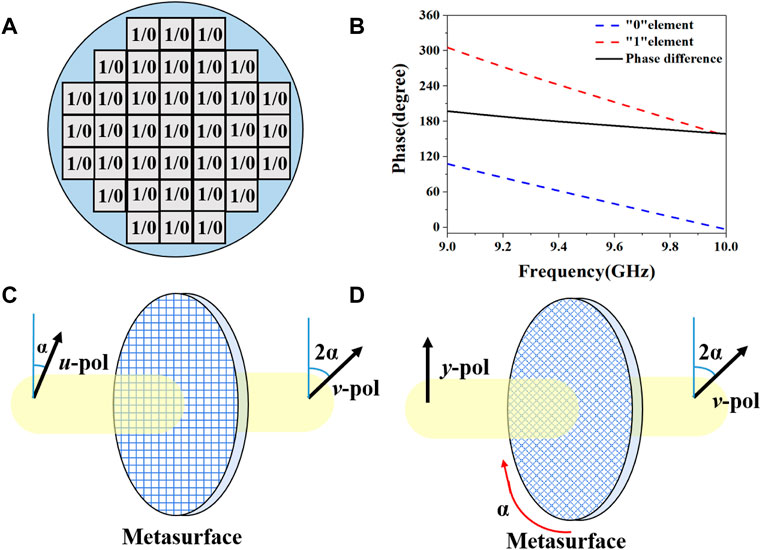
FIGURE 1. A 1-bit digital metasurface and coding metasurface. (A) The 1-bit digital metasurface is composed of the “1/0” elements. (B) The “0” and “1” elements in the “1/0” element and the corresponding phase responses in a range of frequencies. (C) The polarization angle of the transmitted wave is rotated by rotating the polarization angle of the incident wave. (D) The polarization angle of the transmitted wave is rotated by rotating the azimuth angle of the designed metasurface.
The “1/0” elements were arranged as shown in Figure 1A by ensuring that the horizontally polarized wave channel corresponds to the fast axis of the optical path, and the vertically polarized wave channel corresponds to the slow axis of the optical path. We define the vertical polarization direction is the direction perpendicular to the ground plane. As shown in Figure 1C, when the angle between the polarization direction of the incident wave and the vertical polarization direction is α degrees, the polarization direction of the transmitted wave turns 2α degrees in the direction of the vertically polarized wave. Suppose the wave source is fixed, as shown in Figure 1D, rotating the azimuth angle of the designed metasurface from 0 to 90° mechanically; a continuous rotation from 0 to 180 degrees of the polarization angle of the transmitted wave can be achieved. Hence, we can convert a linearly polarized wave to any other desired linearly polarized wave.
In order to reduce the area of the metasurface and improve utilization, we integrate two orthogonal linear polarization wave channels in the same unit. Each unit has two channels, representing the horizontal polarization wave with phase
The element is designed as the transmission-control structure. The proposed functions can be achieved by sandwiching two patches with a transmission-control stripline. The element’s structure is illustrated in Figure 2, comprising five metallic layers (yellow parts) with the thickness of 0.035 mm, and separated by four dielectric substrate layers (grey parts) with the thicknesses h1 and h2 with values of 1.524 and 0.508 mm, respectively. The substrates (Rogers 4350B) have a relative permittivity εr of 3.48 and a loss tangent tan δ of 0.0037. The top and bottom patches of the unit are shown in Figure 2A. The two layers of patches are the same except for the position of the feed point. Figures 2B,D show two grounds, each with two isolation holes to avoid the direct connection with the metallic via-holes. The diameter d of the metallic via-holes is dg = 1 mm. The unit has two groups of metallic cylinders, which transmit x-polarized waves and y-polarized waves. The metalized cylinder transmitting the y-polarized wave is directly connected to the upper and lower patches encoded by the '0′ element. At the same time, the other metallic cylinder is encoded by the “1” element, transmitting an x-polarized wave, and is connected with the upper and lower patches through the middle layer stripline. The unit’s period p affects the working frequency band of the device. We make the metasurface work in the X-band, so the period is p = 11.05 mm. When the size of the top and bottom patches L matches the position of the metallic cylinders, transmission can be carried out at the specified frequency. The geometric dimensions of the device are L = 7.22mm, fx = 2mm, fy = 1.93mm, d = 0.5 mm. The middle layer stripline of the metasurface unit is shown in Figure 2C, and its length controls the transmission phase of the transmitted x-polarized wave. It will be discussed in more detail later. Figure 2F shows the side view of the DPM unit, making each layer’s structure clearer.
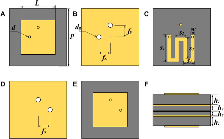
FIGURE 2. The geometry of the proposed continuous polarization angle rotation DPM unit. (A) The top patch and its feed points. (B) The ground layer; (C) The middle layer of stripline. (D) The ground layer; (E) The bottom patch and its feed points. (F) The side view of the DPMs unit.
The design of the middle layer stripline is shown in Figure 2C. The transmission line is carefully designed to have good impedance matching with the top and bottom layers because its total length controls the transmission phase of the x-polarized wave. The metalized cylinders at both ends of the stripline connect the top and bottom patches through isolation holes on the grounds. The transmission line is bilaterally symmetrical along the central axis of the unit; the parameters of the middle layer are set as w = 0.6 mm, s1 = 4.3 mm, s2 = 2.1 mm, s3 = 3.6 mm, s4 = 1.8 mm, where s3 is a variable to control the phase difference between x-polarized wave and y-polarized wave.
Figure 3 shows some simulation results of units with different s3. Txx represents the x-polarized transmitted wave due to an incident x-polarized wave. Tyy represents the y-polarized transmitted wave due to an incident x-polarized wave. Figures 3A–D sketch the relationships between the amplitude/phase of the transmitted wave and different s3, respectively. It can be claimed that changing the length of s3 makes no difference in the transmission of y-polarized waves. The amplitude and phase of y-polarized waves almost have no fluctuation. Furthermore, the transmissivity is always above 0.9. Conversely, by controlling the length of s3, the transmission phase of x-polarized waves can be adjusted separately, while the amplitude of x-polarized waves remains approximately constant.
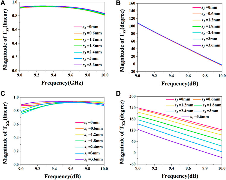
FIGURE 3. Simulation results for different s3. (A) Emitting the y-polarized wave and the amplitude of the transmitted y-polarized wave with different s3. (B) Emitting the y-polarized wave and the phase of the transmitted y-polarized wave with different s3. (C) Emitting x-polarized wave and the amplitude of the transmitted x-polarized wave with different s3. (D) Emitting x-polarized wave and the amplitude of the transmitted x-polarized wave with different s3.
To meet both the “0” and “1” coding and the rotation of the polarization angle, we select the unit with s3 = 3.6 mm, which makes the phase difference between x-polarized waves and y-polarized waves 180°.
In order to explore the continuous polarization angle rotation function of the designed DPM unit, we simulated the unit in the CST Microwave Studio.
Firstly, the initial emission of y-polarized waves is assessed, which is shown in Figure 4A,B. Tyy represents the y-polarized transmitted wave due to an incident y-polarized wave. Txy represents the x-polarized transmitted wave due to an incident y-polarized wave. When emitting y-polarized waves with an angle of 0° with the fast axis, as shown in Figure 4A, the transmitted wave is y-polarized, and the transmissivity at 9.4 GHz can reach 95%. When the metasurface rotates at 45°, the angle between the incident wave and the fast axis is 45°. As shown in Figure 4B, the polarization of the transmitted wave turns to the x polarization. Compared with the incident wave in the previous step, the polarization angle is rotated by 90°, meeting the twofold of the DPM’s rotation angle.
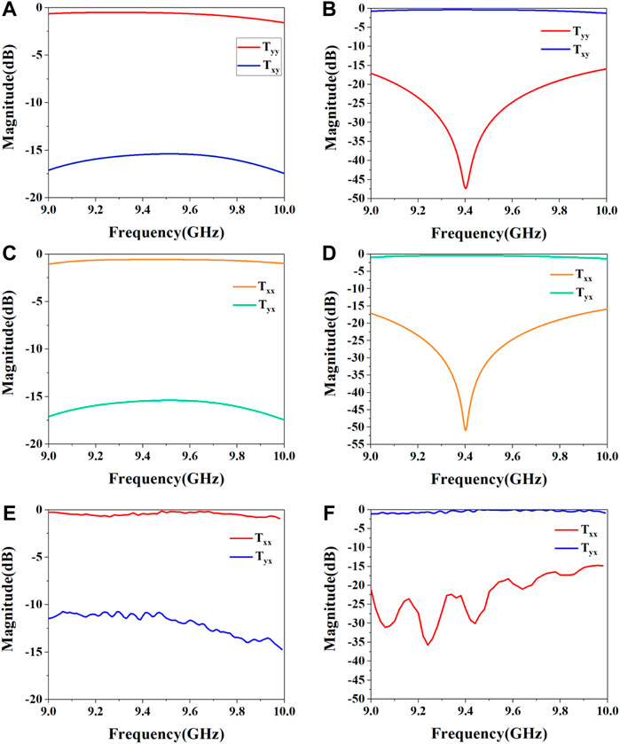
FIGURE 4. (A,B) are the results when the initial emission is a y-polarized wave; (C,D) are the results when the initial emission is an x-polarized wave. (E,F) are the measurement results when the initial emission is an x-polarized wave. (A) The co-polarized transmissivity (Tyy) and the cross-polarized transmissivity (Txy) without rotating the DPM. (B) The co-polarized transmissivity (Tyy) and the cr-polarized transmissivity (Txy) with the DPM rotating 45°. (C) The co-polarized transmissivity (Txx) and the cr-polarized transmissivity (Tyx) without rotating the DPM. (D) The co-polarized transmissivity (Txx) and the cr-polarized transmissivity (Tyx) with the DPM rotating 45°. (E) The co-polarized transmissivity (Txx) and the cr-polarized transmissivity (Tyx) without rotating the DPM. (F) The co-polarized transmissivity (Txx) and the cr-polarized transmissivity (Tyx) with the DPM rotating 45°.
The simulation result of an emitting x-polarized wave is shown in Figure 4C,D. Txx represents the x-polarized transmitted wave due to an incident x-polarized wave. Tyx represents the y-polarized transmitted wave due to an incident x-polarized wave. As Figure 4C shows, when the x-polarized wave with an angle of 0° to the fast axis is emitted, the transmitted wave is x-polarized, and the transmittance at 9.4 GHz can reach up to 95%. Rotating the metasurface by 45°, as shown in Figure 4D, the transmitted wave turns into the y-polarized wave. The polarization angle is rotated by 90°, which meets the twice as much.
These simulation results indicate that by rotating the azimuth angle of the designed metasurface mechanically, a continuous rotation of the polarization angle of the transmitted wave can be achieved.
In addition, we also explored whether oblique incidence affects the function of the proposed DPM. we defined the incident angle of an electromagnetic wave as θ and tested θ= 0°, 15°, 30°, and 45° separately. The simulation results are shown in Figure 5. Figures 5A,B show the transmission when TE polarized waves oblique incidence, and Figure 5C,D show the transmission when TM polarized waves oblique incidence. The simulation results display that the transmission curve of oblique incidence is the same as that of vertical incidence. Therefore, the oblique incidence will not affect the continuous polarization angle rotation ability of the designed DPM.
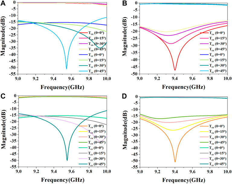
FIGURE 5. (A,B) are the continuous polarization angle rotation ability of the designed DPM unit at TE polarized waves oblique incidence. (C,D) are the continuous polarization angle rotation ability of the designed DPM unit at TM polarized waves oblique incidence. (A) The co-polarized transmissivity (Tco) and the cross-polarized transmissivity (Tcr) without rotating the DPM with different incident angle θ. (B) The co-polarized transmissivity (Tco) and the cr-polarized transmissivity (Tcr) with the DPM rotating 45° with different incident angle θ. (C) The co-polarized transmissivity (Tco) and the cr-polarized transmissivity (Tcr) without rotating the DPM with different incident angle θ. (D) The co-polarized transmissivity (Tco) and the cr-polarized transmissivity (Tcr) with the DPM rotating 45° with different incident angle θ.
To demonstrate that our designed DPM has continuous polarization angle rotation, we further made a circular metasurface with DPM units for an actual measurement. The physical map of the metasurface is shown in Figure 6A. Continuous polarization angle rotation DPM consists of 1065 units with a total size of 425 mm diameter circle. The measurement setup for the continuous rotation polarization angle capability of the metasurface is shown in Figure 6B–D. We use two standard horn antennas of X-band as the transmitting (Tx) and receiving (Rx/Ry) antennas, respectively. Tx transmits an x-polarized wave, and Rx and Ry receive an x-polarized wave and a y-polarized wave separately. The switching between Rx and Ry is realized by rotating the same horn antenna by 90°. A hollow absorbing material plate is utilized to support the DPM since it can reduce the disturbance caused by clutters. The center of the DPM is in direct line with that of the receiving and transmitting horn antennas (Tx and Rx/Ry). First, we calibrated the measuring device, which makes the amplitude of co-polarized transmission (Txx) to 1 and the amplitude of cross-polarized transmission (Tyx) to 0 when the metasurface is not placed. Next, the DPM is placed in the empty space of the absorbing material so that the fast axis of the metasurface (the axis where the “0” element is located) is aligned with the amplitude direction of the wave emitted by the transmitting antenna. When the receiving antenna is parallel to the transmitting antenna, the measured S21 can be regarded as the co-polarized transmission amplitude of DPM. While rotating the receiving antenna 90° to make sure it is perpendicular to the transmitting antenna, the measured S21 will be regarded as the cross-polarization transmission amplitude of DPM.
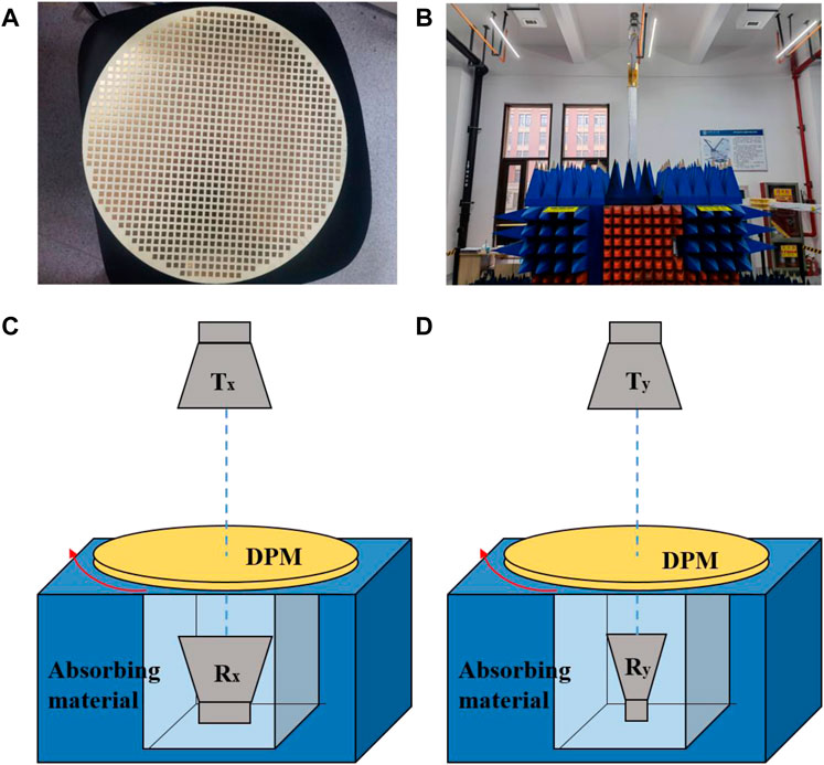
FIGURE 6. Transmission coefficients measurement setup for DPM. (A) The proposed circular metasurface with DPM units. (B) The measurement configuration. (C,D): The switching between Rx and Ry is realized by rotating the same horn antenna by 90°.
Figure 4E shows the polarization of the transmitted wave when the DPM is not rotating. The co-polarized transmission is higher than −1 dB while the cross-polarized transmission is lower than −10 dB, which means that if the angle between the amplitude direction of the incident wave and the fast axis of the metasurface is 0°, the polarization angle of the transmitted wave does not rotate. For the 45 degrees of rotation of the DPM, the cr-polarized transmission is higher than −1 dB while the co-polarized transmission is lower than 10 dB, which is given in Figure 4F. It is pretty evident that if the angle between the amplitude direction of the incident wave and the fast axis of the metasurface is 45°, the amplitude direction of the transmitted wave rotates twice of the angle, and the polarization angle rotates by 90°. Our measurement is consistent with the simulation result.
Furthermore, we have implemented a radar detection experiment under the vertical incidence with an anisotropic target to demonstrate the continuous polarization angle rotation function of the DPM and its practical use for polarimetric radar. Figure 7 gives the outline of the anisotropic grating we prepared to simulate polarization-sensitive targets. Metal strips evenly arrange the gratings with a width of n at an interval of m. The geometric dimensions of the grating are m = 8 mm, and n = 4 mm. Its working frequency band is about 9.4 GHz. The grating has different reflectivity for different linear polarization waves at 9.4 GHz, with the highest reflection for y-polarized waves and almost no reflection for x-polarized waves. The reflection of the anisotropic grating is overly sensitive to the polarization of the incident wave.
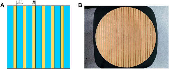
FIGURE 7. (A)The anisotropic grating unit works at about 9.4 GHz. (B) The real picture of the anisotropic grating.
The radar detection experiment is depicted in Figure 8. We use two standard horn antennas of X-band as the transmitting (Ty) and receiving (Ry) antennas, respectively. Ty transmits a y-polarized wave, and Ry receives a y-polarized wave. Firstly, we put the grating on the absorbing material to reduce the influence of surrounding clutter on the experiment and calibrate the co-polarized reflection amplitude of the anisotropic grating without metasurface as 1. Next, we placed the DPM on the anisotropic grating, ensuring the DPM center was directly aligned with the center of the transceiver horn antenna (Ty and Ry). Similarly, the fast axis of the DPM is aligned with the long axis of the anisotropic grating. By rotating the DPM counterclockwise, the measured S21 can be regarded as the reflection amplitude of the anisotropic grating after covering the DPM. Figure 9 shows that reflectivity decreases from the highest point to the lowest point and rises to the top point again by rotating the azimuth angle of the DPM from 0 to 90°. Because the anisotropic grating has the highest reflectivity for y-polarized waves and the lowest reflectivity for x-polarized waves, the measurement result implies that with the mechanical rotation of the DPM by 90°, the polarization of the transmitted wave rotates continuously by 180°. The ability of our designed DPM to continuously rotate the polarization angle has been verified once again.
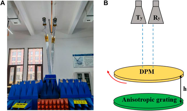
FIGURE 8. The radar detection experiment. (A) The measurement configuration. (B) The DPM is placed on the anisotropic grating, and only the DPM is rotated.
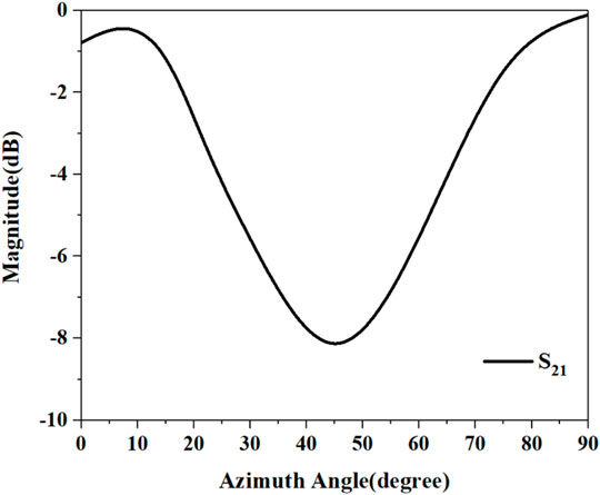
FIGURE 9. The reflection coefficient of anisotropic grating when rotating the DPM counterclockwise.
Moreover, by rotating our proposed DPM, the grating can either entirely reflect electromagnetic waves or not. In the application of radar, the anisotropic target can be detected by rotating the azimuth angle of the designed metasurface mechanically, which is outstandingly practical. In practical engineering applications, metasurface and radar are always used together, and the position is fixed, so we only carried out the radar detection experiment under the vertical incidence.
In conclusion, a method of realizing continuous polarization angle rotation by polarization coding is proposed and experimentally verified. Unlike the previous designs, the structure unit integrates two polarization channels, and each channel is encoded by 1 bit with “0” and “1” elements. It can rotate the polarization angle of the transmitted wave continuously from 0 to 360° by mechanically rotating the metasurface. The transmitted wave of the designed DPM at different angles of mechanical rotation is numerically simulated, and the results show that our design is feasible. On the basis of which, the circular DPM is fabricated and measured. It shows that the continuous rotation of the transmitted wave polarization angle from 0 to 180° can be realized by mechanically rotating the azimuth angle of the designed DPM from 0 to 90°, and there is a double relationship between the polarization angle of rotation and the azimuth angle. The transmittance about 9.4 GHz is higher than 95%. In addition, a radar detection experiment was implemented with an anisotropic target, which further demonstrated the continuous polarization angle rotation function of the DPM we presented. The proposed metasurface has the advantages of continuous polarization rotation, simple structure, and easy integration. It has excellent practical use in the field of radar application. In addition, the polarization and wavefront of electromagnetic waves can be controlled simultaneously according to our proposed coding method.
The raw data supporting the conclusion of this article will be made available by the authors, without undue reservation.
YW, HS, HL, and JC contributed to the conception and design of the study. YW designed the model and wrote the first draft of the manuscript. YW and HS conducted data analysis. HS, JY, LD, AZ, and HL provided resources. All authors contributed to manuscript revision, read, and approved the submitted version.
The authors declare that the research was conducted in the absence of any commercial or financial relationships that could be construed as a potential conflict of interest.
All claims expressed in this article are solely those of the authors and do not necessarily represent those of their affiliated organizations, or those of the publisher, the editors, and the reviewers. Any product that may be evaluated in this article, or claim that may be made by its manufacturer, is not guaranteed or endorsed by the publisher.
Argyres, P. N. (1955). Theory of the Faraday and Kerr Effects in Ferromagnetics. Phys. Rev. 97 (2), 334–345. doi:10.1103/PhysRev.97.334
Arikawa, T., Wang, X., Belyanin, A. A., and Kono, J. (2012). Giant Tunable Faraday Effect in a Semiconductor Magneto-Plasma for Broadband Terahertz Polarization Optics. Opt. Express 20 (17), 19484–19492. doi:10.1364/OE.20.019484
Chipman, R. A., Lam, W., and Young, G. (2018). Polarized Light and Optical Systems (Optical Sciences and Applications of Light). Boca Raton: CRC Press
Cui, T. J., Qi, M. Q., Wan, X., Zhao, J., and Cheng, Q. (2014). Coding Metamaterials, Digital Metamaterials and Programmable Metamaterials. Light Sci. Appl. 3 (10), e218. doi:10.1038/lsa.2014.99
Elston, S. J., Bryan-Brown, G. P., and Sambles, J. R. (1991). Polarization Conversion from Diffraction Gratings. Phys. Rev. B 44 (12), 6393–6400. doi:10.1103/PhysRevB.44.6393
Fei, P., Vandenbosch, G. A. E., Guo, W., Wen, X., Xiong, D., Hu, W., et al. (2020). Versatile Cross‐Polarization Conversion Chiral Metasurface for Linear and Circular Polarizations. Adv. Opt. Mat. 8 (13), 2000194. doi:10.1002/adom.202000194
Gao, X., Han, X., Cao, W.-P., Li, H. O., Ma, H. F., and Cui, T. J. (2015). Ultrawideband and High-Efficiency Linear Polarization Converter Based on Double V-Shaped Metasurface. IEEE Trans. Antennas Propagat. 63 (8), 3522–3530. doi:10.1109/TAP.2015.2434392
Greatbatch, I. (2012). Polarimetric Radar Imaging: from Basics to Applications, by Jong-Sen Lee and Eric Pottier. Int. J. Remote Sens. 33 (2), 661–662. doi:10.1080/01431161.2010.535193
Guan Jin-Ge, J. G., Zhu Jing-Ping, J. P., Tian Heng, H., and Hou Xun, X. (2015). Real-time Polarization Difference Underwater Imaging Based on Stokes Vector. Acta Phys. Sin. 64 (22), 224203. doi:10.7498/aps.64.224203
Hsiao, H.-H., Chu, C. H., and Tsai, D. P. (2017). Fundamentals and Applications of Metasurfaces. Small Methods 1 (4), 1600064. doi:10.1002/smtd.201600064
Ilyas, S., Raza, A., Ahmed, F., Shah, S. M. Q. A., Shoaib, N., and Khan, M. U. (2020). A Multiband and Multifunctional Metasurface for Polarization Conversion Applications,” in IEEE International Symposium on Antennas and Propagation and North American Radio Science Meeting. 985 doi:10.1109/IEEECONF35879.2020.9329677
Jia, Y., Liu, Y., Gong, S., Zhang, W., and Liao, G. (2017). A Low-Rcs and High-Gain Circularly Polarized Antenna with a Low Profile. Antennas Wirel. Propag. Lett. 16, 2477–2480. doi:10.1109/LAWP.2017.2725380
Jiang, L., Li, N., Zhang, L.-z., Wang, C., An, Y., and Hu, Y. (2016). Polarization Control Strategy of a Laser Communication Terminal with a Periscopic Scanner Using Dual Rotating Waveplates. Appl. Opt. 55 (33), 9594–9600. doi:10.1364/AO.55.009594
Ke, J. C., Dai, J. Y., Chen, M. Z., Wang, L., Zhang, C., Tang, W., et al. (2021). Linear and Nonlinear Polarization Syntheses and Their Programmable Controls Based on Anisotropic Time‐Domain Digital Coding Metasurface. Small Struct. 2 (1), 2170003. doi:10.1002/sstr.202170003
Li, S., Wei, M., Feng, X., Wang, Q., Xu, Q., Xu, Y., et al. (2019). Polarization-insensitive Tunable Terahertz Polarization Rotator. Opt. Express 27 (12), 16966. doi:10.1364/OE.27.016966
Liu, H., Huang, X., Han, F., Cui, J., Spencer, B. F., and Xie, X. (2019). Hybrid Polarimetric Gpr Calibration and Elongated Object Orientation Estimation. IEEE J. Sel. Top. Appl. Earth Obs. Remote Sens. 12 (99), 2080–2087. doi:10.1109/JSTARS.2019.2912339
Ma, Q., Hong, Q. R., Bai, G. D., Jing, H. B., Wu, R. Y., Bao, L., et al. (2020). Editing Arbitrarily Linear Polarizations Using Programmable Metasurface. Phys. Rev. Appl. 13 (2), 1003. doi:10.1103/PhysRevApplied.13.021003
Meissner, T., and Wentz, F. J. (2006). Polarization Rotation and the Third Stokes Parameter: the Effects of Spacecraft Attitude and Faraday Rotation. IEEE Trans. Geosci. Remote Sens. 44 (3), 506–515. doi:10.1109/TGRS.2005.858413
Mutlu, M., and Ozbay, E. (2012). A Transparent 90° Polarization Rotator by Combining Chirality and Electromagnetic Wave Tunneling. Appl. Phys. Lett. 100 (5). doi:10.05190910.1063/1.3682591
Nur-E-Alam, M., Vasiliev, M., and Alameh, K. (2009). Nano-structured Magnetic Photonic Crystals for Magneto-Optic Polarization Controllers at the Communication-Band Wavelengths. Opt. Quant. Electron 41 (9), 661–669. doi:10.1007/s11082-010-9374-2
Overvig, A. C., Shrestha, S., Malek, S. C., Lu, M., Stein, A., Zheng, C., et al. (2019). Dielectric Metasurfaces for Complete and Independent Control of the Optical Amplitude and Phase. Light Sci. Appl. 8 (1), 12. doi:10.1038/s41377-019-0201-7
Pazmany, A. L., Mead, J. B., Bluestein, H. B., Snyder, J. C., and Houser, J. B. (2013). A Mobile Rapid-Scanning X-Band Polarimetric (Raxpol) Doppler Radar System. J. Atmos. Ocean. Technol. 30 (7), 1398–1413. doi:10.1175/JTECH-D-12-00166.1
Rahman, S. U., Cao, Q., Akram, M. R., Amin, F., and Wang, Y. (2020). Multifunctional Polarization Converting Metasurface and its Application to Reduce the Radar Cross-Section of an Isolated Mimo Antenna. J. Phys. D. Appl. Phys. 53 (308pp), 305001. doi:10.3389/fendo.2013.0000610.1088/1361-6463/ab85e7
Shi, J. H., Ma, H. F., Jiang, W. X., and Cui, T. J. (2012). Multiband Stereometamaterial-Based Polarization Spectral Filter. Phys. Rev. B 86 (3), 0351031–1035103. doi:10.1103/PhysRevB.86.035103
Si-Wei Chen, S. W., Xue-Song Wang, X. S., and Sato, M. (2014). Uniform Polarimetric Matrix Rotation Theory and its Applications. IEEE Trans. Geosci. Remote Sens. 52, 4756–4770. doi:10.1109/TGRS.2013.2284359
Su, P., Zhao, Y., Jia, S., Shi, W., and Wang, H. (2016). An Ultra-wideband and Polarization-independent Metasurface for Rcs Reduction. Sci. Rep. 6, 20387. doi:10.1038/srep20387
Wang, D., GuGu, Y., Gong, Y., Qiu, C.-W., and Hong, M. (2015). An Ultrathin Terahertz Quarter-Wave Plate Using Planar Babinet-Inverted Metasurface. Opt. Express 23, 11114. doi:10.1364/OE.23.011114
Wei, Z., Cao, Y., Fan, Y., Yu, X., and Li, H. (2011). Broadband Polarization Transformation via Enhanced Asymmetric Transmission through Arrays of Twisted Complementary Split-Ring Resonators. Appl. Phys. Lett. 99 (22), 221907. doi:10.1063/1.3664774
Xu, J., Li, T., Lu, F. F., Wang, S. M., and Zhu, S. N. (2011). Manipulating Optical Polarization by Stereo Plasmonic Structure. Opt. Express 19 (2), 748–756. doi:10.1364/OE.19.000748
Yang, H., Cao, X., Yang, F., Gao, J., Xu, S., Li, M., et al. (2016). A Programmable Metasurface with Dynamic Polarization, Scattering and Focusing Control. Sci. Rep. 6, 35692. doi:10.1038/srep35692
Yokoyama, M., and Noda, S. (2003). Polarization Mode Control of Two-Dimensional Photonic Crystal Laser Having a Square Lattice Structure. IEEE J. Quantum Electron. 39 (9), 1074–1080. doi:10.1109/jqe.2003.816098
Zhang, J., Song, L., Du, Q., and Chen, Y. (2018). A Wideband Digital Polarization Synthesis Method. Int. J. RF Microw. Comput. Aided Eng. 28 (9), e21411. doi:10.1002/mmce.21411
Zhang, M., Zhang, W., Liu, A. Q., Li, F. C., and Lan, C. F. (2017). Tunable Polarization Conversion and Rotation Based on a Reconfigurable Metasurface. Sci. Rep. 7 (1), 12068. doi:10.1038/s41598-017-11953-z
Keywords: metasurface, polarization rotation, digital polarization programmable, radar application, X band
Citation: Wang Y, Shi H, Chen J, Yi J, Dong L, Zhang A and Liu H (2022) Digital Polarization Programmable Metasurface for Continuous Polarization Angle Rotation and Radar Applications. Front. Mater. 9:931868. doi: 10.3389/fmats.2022.931868
Received: 29 April 2022; Accepted: 25 May 2022;
Published: 08 June 2022.
Edited by:
Bin Yang, University of Chester, United KingdomReviewed by:
Wenxuan Tang, Southeast University, ChinaCopyright © 2022 Wang, Shi, Chen, Yi, Dong, Zhang and Liu. This is an open-access article distributed under the terms of the Creative Commons Attribution License (CC BY). The use, distribution or reproduction in other forums is permitted, provided the original author(s) and the copyright owner(s) are credited and that the original publication in this journal is cited, in accordance with accepted academic practice. No use, distribution or reproduction is permitted which does not comply with these terms.
*Correspondence: Hongyu Shi, aG9ueW8uc2hpMTk4N0BnbWFpbC5jb20=
Disclaimer: All claims expressed in this article are solely those of the authors and do not necessarily represent those of their affiliated organizations, or those of the publisher, the editors and the reviewers. Any product that may be evaluated in this article or claim that may be made by its manufacturer is not guaranteed or endorsed by the publisher.
Research integrity at Frontiers
Learn more about the work of our research integrity team to safeguard the quality of each article we publish.