 Zida Xiao
 Hongsheng Hu
 Qing Ouyang
 Liyang Shan3
95% of researchers rate our articles as excellent or good
Learn more about the work of our research integrity team to safeguard the quality of each article we publish.
Find out more
ORIGINAL RESEARCH article
Front. Mater. , 06 July 2022
Sec. Smart Materials
Volume 9 - 2022 | https://doi.org/10.3389/fmats.2022.930825
This article is part of the Research Topic Characterization and Application of Magneto-sensitive Soft Materials View all 20 articles
To reveal the transient temperature distribution pattern inside the magnetorheological grease (MRG) torsional vibration damper and explore the relationship between the current and internal temperature of the device, the transient temperature simulation analysis of the MRG device was conducted in this study. Firstly, a theoretical heat transfer model of MRG torsional vibration damper with dual heat source structural feature was established based on the Bingham constitutive model and the temperature-dependent viscosity characteristic of MRG. Then, the transient temperature field model of the MRG torsional vibration damper was developed by the finite element method, the temperature field distribution and temperature–time variation characteristics of the MRG torsional vibration damper at 0A, 1A, and 2A working conditions were analyzed, and the effects of viscosity and slip factors on the temperature rise of the device were investigated. The simulation results show that the temperature rise of MRG in the working domain is the fastest, but a gradual slowing of the temperature rise rate. The magnitude and rate of temperature rise are maximum when the 1A current is applied to the torsional vibration damper. Finally, the current–temperature curve is obtained by fitting the simulation results. The results of the analysis reveal the internal temperature distribution and temperature rise characteristics of the torsional vibration damper, which provide a theoretical basis for the structural optimization and control strategy design of the MRG torsional vibration damper considering temperature as a factor.
In engine systems, the power source for crankshaft rotation is the explosive force generated by the instantaneous combustion of combustible gases in the cylinder, and explosive force is transmitted to the crankshaft through the piston and other parts. This process leads to torsional–detorsional effects on the crankshaft, which further lead to torsional vibration of the crankshaft (Boysal and Rahnejat 1997). For multi-cylinder engines, the crankshaft system comes with a large number of pistons, connecting rods, flywheels, and other accessories (Periyasamy and Alwarsamy 2012). Large rotational inertia, high speed, high load (Karabulut 2012), and cylinder ignition unevenness (Zhang and Yu 2009) make the torsional vibration of the crankshaft more intense, especially in the starting phase with high acceleration. To prevent the crankshaft from torsional deformation or failure, the crankshaft torsional vibration must take effective reduction measures (Fonte and de Freitas 2009). At present, the main reduction measure for crankshaft torsional vibration is to install a torsional vibration damper in the crankshaft system, which can well avoid crankshaft torsional vibration caused by resonance and reduce the amplitude of torsional vibration (Mendes et al., 2008).
So far, the torsional vibration damper that has been produced and put into use are silicone oil dampers (Pistek et al., 2017), rubber dampers (Silva et al., 2019), silicone oil–rubber composite torsional vibration dampers (Li et al., 2020) and dual-mass flywheel torsional vibration dampers (Long et al., 2021). However, these dampers only show a good damping effect at a specific resonance frequency due to which the damping is uncontrollable (Shu et al., 2015). Therefore, magnetorheological smart materials were introduced to develop the magnetorheological torsional vibration damper (Abouobaia et al., 2016, 2020; Brancati et al., 2019). The installation of the damper at the free end of the crankshaft can prevent the crankshaft from torsional failure, but then comes the problem of damper heat dissipation. Generally, damping materials such as silicone oil, MRG, and other viscous liquids need to be overhauled after a period of operation to ensure that the damping material does not fail due to high temperature (Homik 2010).
MRG is a variable damping smart material whose damping characteristics, magnetic field characteristics, and settlement characteristics have obvious temperature dependence (Sahin et al., 2009; Meyer et al., 2016; McKee et al., 2017; Liang et al., 2021). Rheological characteristics of MRG vary in different magnetic fields and temperatures (Kamble et al., 2021). If the temperature is not analyzed and suppressed, the MRG torsional vibration damper will not only fail to dampen the torsional vibration but also further aggravate the vibration of the crankshaft system due to its own heavy mass.
At present, there are many studies on the temperature analysis of viscous fluid torsional vibration dampers and magnetorheological rotary dampers. Homik et al. proposed a thermal fluid dynamics model for viscous torsional vibration dampers and investigated the effect of temperature and viscosity variations of the damping fluid inside the torsional vibration damper on the efficiency of the torsional vibration damper (Homik, 2012; Homik et al., 2021). Venczel et al. developed a two-dimensional thermal calculation program based on the finite difference method, analyzed the heat transfer process inside silicone oil dampers, and developed a temperature and shear rate–dependent viscosity model for the silicone fluid (Venczel and Veress. 2020; Venczel et al., 2021). Gordaninejad et al. conducted an experimental and theoretical study of heat generation and dissipation in magnetorheological dampers, developed a theoretical model for predicting the temperature rise of magnetorheological dampers, and developed a control equation in the dimensionless form (Gordaninejad and Breese, 1999). Batterbee et al. quantified the effect of temperature on the damper between 15°C and 75°C and studied the effect of elevated temperature on magnetorheological fluid viscosity and yield stress (Batterbee and Sims 2008). Kavlicoglu et al. (2007) conducted a theoretical and experimental study of heat generation in a high-torque magnetorheological differential clutch, mainly for the effect of temperature on the torque performance of the clutch, and analyzed the temperature rise distribution inside the clutch. Nguyen et al. proposed an optimization method based on finite element analysis for magnetorheological brakes considering temperature factors and used the Bingham model and Herschel–Bulkley model to analyze the braking torque of the brake (Nguyen and Choi 2010). Park et al. (2008) introduced a magnetorheological braking system, and the fluid flow and heat transfer system of the magnetorheological fluid were analyzed considering the critical issues of brake size, performance, and temperature. Patil et al. (2016) performed a thermal analysis of a magnetorheological brake to evaluate the temperature rise of the magnetic fluid due to brake manipulation and performed a finite element analysis of the temperature field of the brake. So far, there have been many studies on the temperature aspects of viscous fluid torsional vibration dampers and magnetorheological dampers. However, there is a lack of temperature analyses of MRG torsional vibration dampers under different working conditions. This study adopts the multi-field coupling method of flow field–temperature field for simulation analysis, which reveals the temperature gradient distribution inside the device in more detail. In this study, based on the temperature rise theory of torsional vibration dampers and the temperature analysis of magnetorheological dampers, the temperature analyses of MRG torsional vibration dampers under different working conditions have been developed.
In this article, a theoretical model of the temperature field of MRG was established based on the Bingham mechanics model and viscosity–temperature model, the heat transfer system of the MRG torsion damper was analyzed, and the heat source and heat generation rate of MRG torsion damper and the internal forced convection heat transfer coefficient were calculated. Secondly, the three-dimensional model of MRG torsional vibration damper was established, and its temperature rise principle was analyzed. The transient temperature field of the MRG torsional vibration damper was simulated and analyzed in the 0A, 1A, and 2A three working conditions. The influence of slip between the inner and outer rotors and the viscosity of MRG on temperature rise was investigated. The results show the distribution pattern of temperature and provide the simulation and theoretical basis for subsequent heat dissipation optimization and temperature compensation control.
The remainder of the article is organized as follows. In Section 2, the temperature characteristics and magnetic field characteristics of MRG were analyzed, the mathematical model of the temperature field of MRG torsional vibration damper was established, and the forced convection heat transfer coefficient was calculated. In Section 3, the three-dimensional transient temperature simulation model of the MRG torsional vibration damper was established, and the temperature rise principle inside the device was analyzed. In Section 4, the results of transient temperature field simulation were analyzed, and the relationship between the current and internal temperature characteristics of the device was explored. Section 5 put forward the conclusion of the study.
The rheological behavior of MRG is described based on the Bingham constitutive model, which is Eq. 1.
where
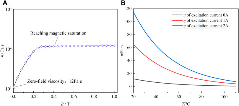
FIGURE 1. (A) Curve of magnetic field characteristics of MRG. (B) Curve of temperature characteristics of MRG.
The viscosity–temperature characteristics of MRG are considered, and the viscosity–temperature equation is Eq. 2 (Zhai et al., 2019).
where
In the rectangular coordinate system, choose a volume element from the MRG torsional vibration damper with length dx, width dy, and height dz. From Fourier’s law of heat conduction, the heat fluxes flow into the element and the heat fluxes flow out of the element are Eq. 3 and 4, respectively.
where
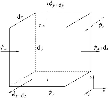
FIGURE 2. Thermal equilibrium analysis of the microelement.
The differential equation for the thermal conductivity of the volume element is shown in Eq. 5.
where
The control energy generated by the coil resistance heat (coil power consumption N) can be expressed by Eq. 6.
where I is the current applied to the excitation coil, and
where r is the resistivity of copper wire (0.01726 [
where
where
where L is the geometric characteristic of the heat transfer surface; in this model, it is the geometric height of the MRG domain. The geometric parameters of the MRG fluid domain are shown in Table 1. c is the specific heat ratio, and its value is 1 (set MRG as incompressible fluid). According to Eq. 10 (Haque et al., 2021), the forced convection heat transfer coefficient h can be calculated. It can be known that the forced convection heat transfer coefficient h is related to the slip, and the h variation curve is shown in Figure 3. The forced convection heat transfer coefficient increases with the increase of slip and the trend is shown in Figure 3A. The heat transfer coefficient is different at each moment due to the different slips at each moment, as is shown in Figure 3B. Since no current is introduced in working condition Ⅲ, the coil does not generate resistive heat, and the heat transfer coefficient of working condition Ⅲ is not studied.
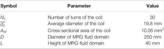
TABLE 1. Parameters of heat transfer model.
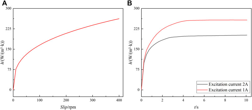
FIGURE 3. h variation curve: (A) h-slip curve and (B) h-t curve of each working condition.
In order to meet the damping requirements of reducing the torsional vibration of the crankshaft under multiple resonance frequencies and ensure closure of the magnetic circuit inside the device, the structure of the internal inertia ring of the MRG torsional damper is designed based on the adjustable damping characteristics of MRG as shown in Figure 4. The MRG is filled between the inner surface of the magnetically conductive ring and the outer surface of the inertia ring and the inner surfaces of the two end caps. When the coil is not energized, the MRG behaves as a free-flowing Newtonian fluid. When the coil is energized, the magnetic field is generated in the working gap and the MRG transforms into a solid-like state, thus viscous damping forces are generated. The MRG torsional vibration damper cross-sectional view and exploded diagram model are shown in Figure 4.
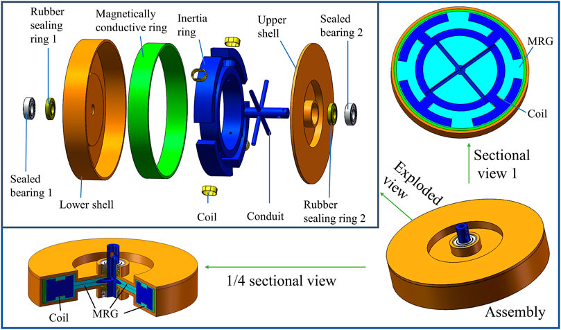
FIGURE 4. MRG torsional vibration damper model.
The MRG torsional vibration damper consists of three key parts: shell, inertia ring, and MRG. The working clearance of MRG is 2 mm. After the crankshaft is fixedly connected to the MRG torsional vibration damper shell, the shell drives the internal inertia ring to rotate through the viscous damping force of the internal MRG.
The main reason for the torsional vibration of crankshaft systems is that the excitation frequency is similar to the natural frequency, resulting in resonance. To avoid resonance, the frequency shift principle is usually adopted, with a change to the natural frequency of the system by changing the stiffness and mass. The MRG torsional vibration damper can change the viscous damping of the internal MRG by adjusting the current, which can control the natural frequency of the whole crankshaft system. Therefore, MRG torsional vibration damper can play a better damping effect at any resonance frequency.
The MRG inside the MRG vibration damper can convert the energy of torsional vibration into internal energy, and the temperature gets warmer as time accumulates due to the engine crankshaft system being a continuous working system. Due to the large rotational inertia of the inertia ring, slip exists between the inner and outer rotors, and the high-viscosity MRG will generate a higher temperature in the gap between the shell and inertia ring due to fluid friction. On the other hand, the coil inside the MRG torsional vibration damper will generate resistance heat, which will also affect the viscous damping effect of the MRG and further affect the damping performance of the MRG torsional vibration damper.
There is a slip between the inner and outer rotors of the MRG torsional vibration damper, and heat will be generated inside the device due to fluid friction. In addition, the coil inside the MRG torsional vibration damper will also generate resistance heat. MRG torsional vibration damper internal heat conduction system is the “dual heat source structure,” the specific heat transfer process is shown in Figure 5.
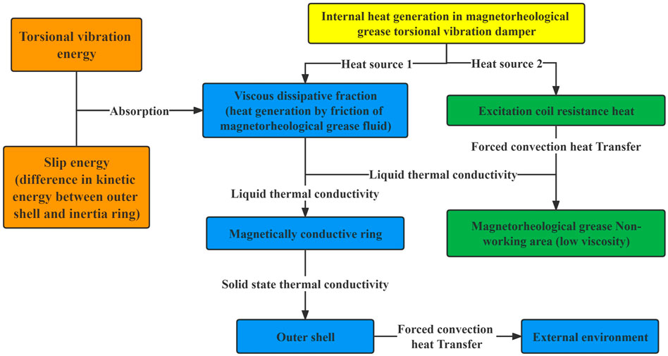
FIGURE 5. Thermal conductivity system.
According to Figure 5, the MRG will transform the slip energy and torsional vibration energy into internal energy, and the heat will be further transferred to the outer shell through the magnetically conductive ring. The shell carries out forced convection heat transfer with the external air, and the heat will dissipate. The resistance heat generated by the coil first conducts forced convection heat transfer with the surrounding MRG, and the temperature of the working domain of the MRG is transferred to the non–working domain of the MRG by liquid heat transfer.
In order to analyze the magnetic excitation line distribution of MRG torsional vibration damper more accurately, the magnetic field simulation of the “Sectional view1” model in Figure 4 is carried out by COMSOL Multiphysics. Figure 6A shows the distribution of magnetic excitation lines inside the MRG torsional vibration damper. When the magnetic field is simulated for the MRG torsional vibration damper, the simulation model is simplified due to the conductor tubes, bearings, and seals that have little influence on the results of the magnetic field simulation. The outermost ring of the MRG fluid domain with higher magnetic excitation line density is defined as the “Working domain of MRG”; the MRG fluid domain with lower internal magnetic excitation line density is defined as the “Non-working domain of MRG.” And the “Route” of the MRG working domain is chosen between the inertia ring and magnetically conductive ring, the magnetic field distribution pattern through this Route is shown in Figure 6B. The magnetic excitation line density decreases from the left end to the right end of the Route, and B decreases with the increase of the distance d between the measurement point and the left end point. The magnetic excitation lines on the left and right sides of the right end point of the Route are symmetrically distributed, and a small amount of coupling exists in the magnetic excitation line, which can be neglected.
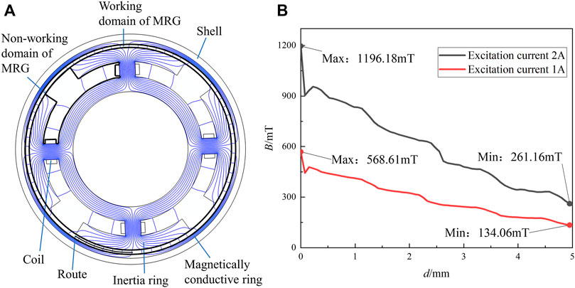
FIGURE 6. Magnetic field simulation: (A) magnetic excitation line distribution and (B) B-d curve.
The COMSOL Multiphysics fluid–solid coupling simulation of the MRG torsional vibration damper requires a Boolean operation to model the fluid domain and divide the overall internal MRG domain into the working domain of MRG and the non–working domain of MRG. The internal inertia ring affects the MRG motion, the rotating inner wall, outer wall, and dynamic mesh settings are needed for the MRG domain separately. During the simulation, the effects of bolts, bearings, seals, friction pads, conductor tubes, etc. are ignored to shorten the simulation time for the Multiphysics field coupling simulation. The reference pressure is 101.325 KPa (standard atmospheric pressure). The model of magnetorheological grease used in this article is MRG-50, the mass fraction of hydroxy iron powder and lubricating grease in this model is 50% each (the lubricating grease adopts No. 2 high-temperature lubricating grease of Shandong Kunlun Lubricating Oil Sales Co., Ltd.). The initial viscosity is 12 Pa s. According to the known density, isobaric specific heat capacity and mass fraction of hydroxyl iron powder and lubricating grease, the density and isobaric specific heat capacity of MRG-50 can be calculated, respectively (Wang et al., 2019). According to the thermal conductivity and mass fraction of hydroxyl iron powder and lubricating grease, the thermal conductivity of MRG-50 is calculated by Filipoov equation (Reid et al., 1987). The fluid properties of the MRG are shown in Table 2.
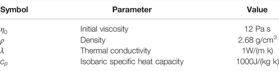
TABLE 2. Fluid parameters of MRG.
The MRG material is defined according to the Bingham model and the viscosity–temperature characteristic equation coupling. The corresponding boundary conditions are set for the fluid: the outer boundary of the fluid is all the inner surfaces of the shell and the rotational boundary inside the fluid is all the outer surfaces of the inertia ring. The whole model is set to “Form the assembly,” and static and dynamic domains are used in “a consistent pair” to ensure the data transfer. The dynamic deformation domain is set by the method of dynamic mesh rotational domain, the rotational boundary speed inside the MRG domain is set and the parameter values are the slip value of the inner and outer rotors. The measured slip values of the tests for the three working conditions are shown in Figure 7.
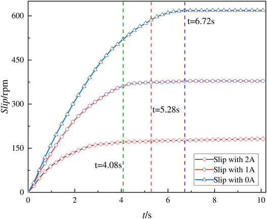
FIGURE 7. Slip of shell and inertia ring for each working condition.
According to Figure 7, the slip between the inner and outer rotors is different when three different currents are applied to the coil: 1A (working condition Ⅰ), 2A (working condition II), and 0A (working condition III). In working condition Ⅱ, due to the higher flux density of the working domain of MRG, the viscous damping force of the MRG is the largest and the slip of the inner and outer rotors is the smallest among the three working conditions, with a slow linear growth trend after the slip reaches 171.34 rpm at 4.08 s. The linear growth trend is shown after the slip reaches 373.66 and 618.60 rpm at 5.28 and 6.72 s for working condition Ⅰ and working condition Ⅲ, respectively.
To ensure the quality of the grid cells, the hydrodynamic refinement grid is set according to the “non-isothermal laminar flow” Multiphysics field simulation. The corner refinement grid is processed for the internal rotating boundary chamfers and edges. The free tetrahedral grid is used for the whole rotating domain and set as the dynamic grid–rotating domain. The grid refinement is conducted for the internal rotating boundary and external boundary of the MRG domain.
To distinguish and judge the temperature rise amplitude and rate of MRG in the different domains, as well as the temperature distribution within the MRG domain, the internal overall MRG domain is divided into the working domain (Figure 8A) and non–working domain (Figure 8B). The spatial coordinates of the temperature measurement points selected in the working domain of MRG, the non–working domain of MRG, and coil domain are as follows: (
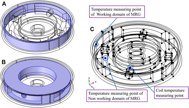
FIGURE 8. Simulation model of transient temperature field: (A) working domain of the MRG, (B) non–working domain of the MRG, and (C) temperature probe picking point.
The temperature distribution and temperature rise inside the torsional vibration damper are carried out for working condition Ⅰ, working condition Ⅱ, and working condition Ⅲ. The simulation step is taken as 0.1 s, and the results are analyzed according to the simulated results of each 0.1 s.
Figure 9 shows the simulation results of the transient temperature field of the MRG torsional vibration damper for working condition Ⅰ. When the 1A current is applied, the coil generates resistance heat at the initial stage, then it conducts forced convection heat transfer with the surrounding MRG. When the slip gradually becomes larger between the inner and outer rotors, the fluid friction gradually becomes more intense in the MRG working domain and the amplitude and rate of temperature rise increase faster. When running for 10 s, the highest temperature domain inside the damper is the MRG work domain, and the temperature of both sides of the end phase is in the range of 47–51°C. The specific temperature rise trend of each domain is shown in Figure 10.
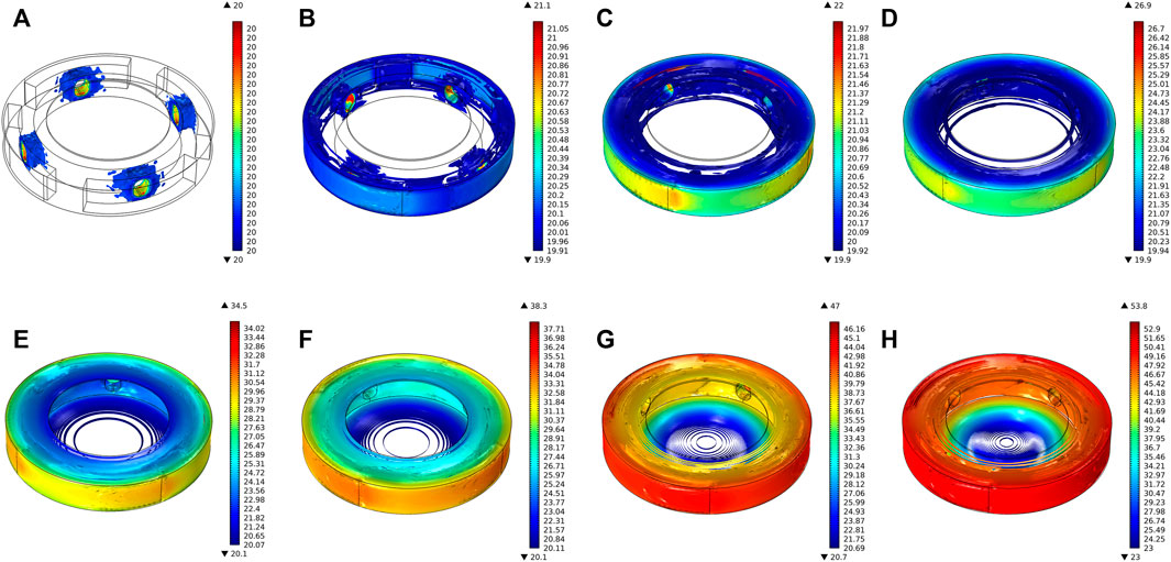
FIGURE 9. Transient temperature distribution of MRG torsional vibration damper for each moment of working condition Ⅰ: (A) t = 0 s, (B) t = 0.4 s, (C) t = 0.8 s, (D) t = 1.5 s, (E) t = 3 s, (F) t = 4 s, (G) t = 7 s, and (H) t = 10 s.
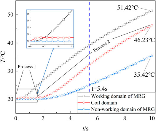
FIGURE 10. Temperature rise curve of each domain in working condition Ⅰ
According to Figure 10, when the 1A current is applied to the coil, the magnitude and rate of temperature rise in the working domain of MRG are the greatest due to higher viscosity, higher slip, and smaller working gap of this domain. The temperature rises rapidly from the initial 20°C–51.42°C. As the temperature increases, the degree of fluid friction is reduced due to the slowing of the increase in the slip and the viscosity–temperature properties of MRG, and the temperature rise rate slows down after 5.4 s. In the process1 stage of Figure 10, the coil is fed with a 1A current, generating resistance heat and forced convection heat transfer with the surrounding MRG. In the process 2 stage, after 1.6 s, the temperature starts to increase due to the heat transfer from the working domain of MRG to the vicinity of the coil through the MRG. The temperature of the MRG at the coil domain is indicated in the “Coil domain” of Figure 10. For the non–working domain of the MRG, the temperature rise amplitude and rate are the lowest due to MRG with low viscosity and a large working gap.
Figure 11 shows the simulation results of the MRG torsional vibration damper working condition II. When the 2A current is applied, the coil will generate resistance heat at the initial stage, then it conducts forced convection heat transfer with the surrounding MRG. The degree of friction of the MRG at the outermost ring increases sharply due to the gradual increase of slip, and the magnitude and rate of temperature rise increase. The specific temperature rise trend of each domain in working condition II is shown in Figure 12.
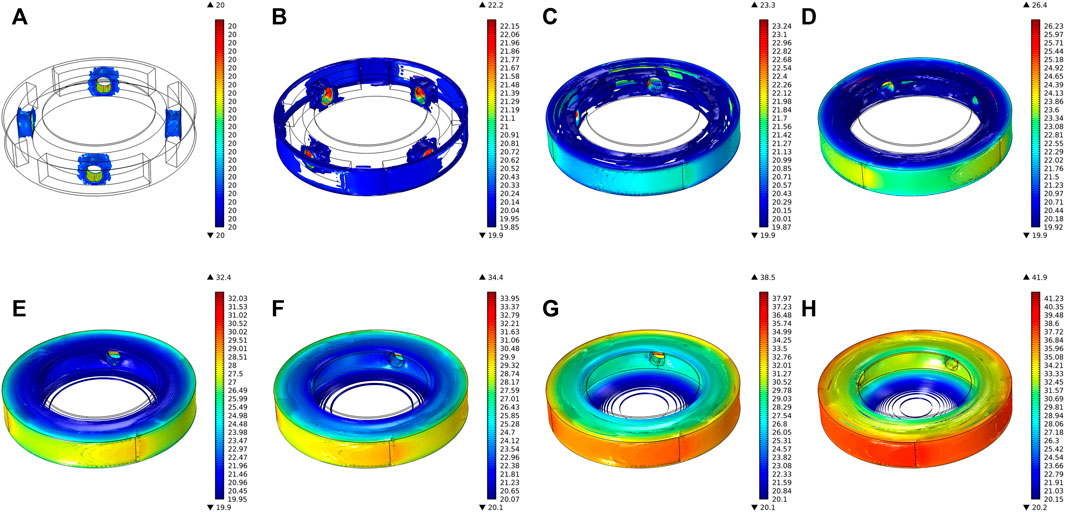
FIGURE 11. Transient temperature distribution of MRG torsional vibration damper for each moment of working condition Ⅱ: (A) t = 0 s, (B) t = 0.4 s, (C) t = 0.8 s, (D) t = 1.5 s, (E) t = 3 s, (F) t = 4 s, (G) t = 7 s, and (H) t = 10 s.
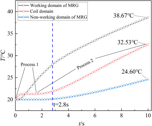
FIGURE 12. Temperature rise curve of each domain in working condition Ⅱ
According to Figure 12, when the 2A current is applied, MRG reaches the magnetic saturation state in the working domain of MRG, when MRG viscosity is maximum but the slip is minimum. Compared to working condition I, the degree of fluid friction is less, the temperature rises rapidly from the initial 20°C to 38.67°C. Due to the slowing of the increase in the slip, the temperature rise rate slows down after 2.8 s. In the process 1 stage of Figure 12, compared to working condition Ⅰ, the resistance heat generated is higher due to increased input current. The resistance heat conducts forced convection heat transfer with the surrounding MRG. In the process 2 stage, after 2 s, the temperature starts to increase due to the heat transfer from the working domain of MRG to the vicinity of the coil through the MRG. The temperature of the MRG at the coil domain is indicated in the “Coil domain” of Figure 12. The temperature at the non–working domain of MRG has the lowest temperature rise amplitude and rate due to the small viscosity and large working gap.
Figure 13 shows the simulation results of the MRG torsional vibration damper under working condition III. When no current is applied to the coil, the viscosity and viscous damping force of MRG are minimum. The slip is the largest between the inner and outer rotors under working condition III. In the starting stage, the internal temperature is set at the initial ambient temperature of 20°C. The amplitude and rate of temperature rise at the working domain due to the slip gradually increase. According to the simulation results, the temperature at the outermost ring on both sides of the end face is nearly the same as the temperature at the working domain in 0–10 s. Since the viscosity of the MRG inside the device is the same in working condition III, the highest temperature inside the torsional vibration damper is at the working domain of the MRG when running for 10s, and the temperature at the two end surfaces is in the range of 38–39°C, which is nearly the same as the temperature of the MRG in the working domain. The specific temperature rise trend in each domain of working condition Ⅲ is shown in Figure 14.
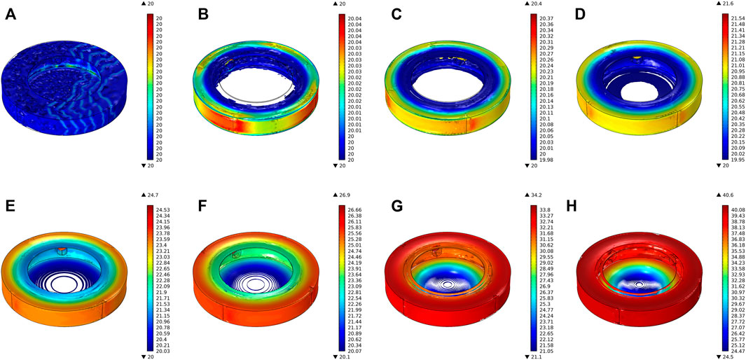
FIGURE 13. Transient temperature distribution of MRG torsional vibration damper for each moment of working condition Ⅲ: (A) t = 0 s, (B) t = 0.4 s, (C) t = 0.8 s, (D) t = 1.5 s, (E) t = 3 s, (F) t = 4 s, (G) t = 7 s, and (H) t = 10 s.
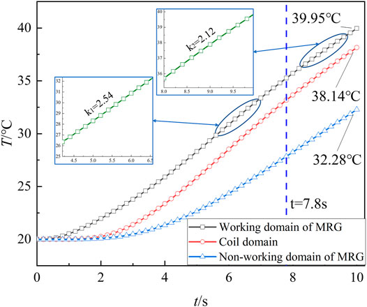
FIGURE 14. Temperature rise curve of each domain in working condition Ⅲ
According to Figure 14, the viscosity of MRG inside the device is consistent when no current is introduced inside the MRG torsional vibration damper. Due to the small working gap in the working domain, the temperature rise of MRG is the largest, and the temperature rises rapidly from the initial 20°C to 39.95°C within 10 s. After 7.8 s, the temperature rise rate slows down due to the slowing of the increase in the slip and the viscosity–temperature characteristics of MRG, and the temperature rise rate decreases from 2.54 to 2.12. The temperature at the coil domain still has a high-temperature rise amplitude and rate due to the heat transfer of MRG. The amplitude and rate of temperature rise at the non–working domain of MRG are the lowest due to the large working gap.
When increasing the current applied to the coil, the viscosity of MRG increases while decreasing the slip between the inner and outer rotors. To explore the relationship between the input current and the internal temperature of the device more precisely, the same transient temperature field simulation analysis was performed for the incoming 0.5 and 1.5A currents, and the peak temperature at the 10-s moment was obtained as shown in Figure 15. When the applied current is 0–1A, the viscosity of the MRG increases rapidly from the initial viscosity to about 75 Pa s, and the slip between the inner and outer rotors decreases accordingly. The increase of viscosity intensifies the fluid friction in the working domain of MRG, which increases the temperature rise rate. When the applied current is 1–2A, the slip of the inner and outer rotors decreases due to the increase of MRG viscosity, and the fluid friction degree is weakened, which reduces the amplitude and rate of temperature rise. For the several common working conditions of the MRG torsional vibration damper studied in this article, the increase of MRG viscosity is the main factor affecting the temperature rise when the applied current is 0–1A. The amplitude and rate of temperature rise are maximum when the 0.852A current is applied by fitting the curve in Figure 15. When the applied current is 1–2A, fluid friction is weakened due to the reduced slip between the inner and outer rotors, thus the amplitude and rate of the temperature rise are lower.
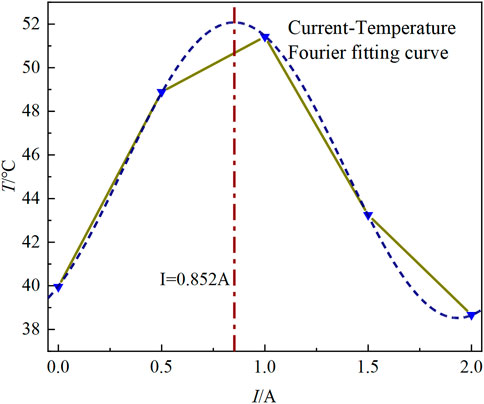
FIGURE 15. Current–temperature curve.
In this study, a multi-field coupling approach is used to simulate and analyze the working conditions of the torsional vibration in the starting phase. The distribution results of the transient temperature field simulation reveal the temperature field distribution and change law inside the MRG torsional vibration damper, and the relationship curve between current and temperature is derived from the simulation results, which provides simulation and theoretical basis for the subsequent heat dissipation optimization and temperature compensation control. Due to the simulation time of the Multiphysics simulation software, this study only simulates several common working conditions, for the effect of current on temperature, the corresponding discrete results are obtained, and then the results are fitted. For the Multiphysics simulation, the corresponding device model is simplified, which has little effect on the simulation of the temperature field.
According to the simulation results of each working condition, the internal temperature distribution pattern of the device is the highest temperature domain for the working domain of MRG. The temperature of both end surfaces gradually increases from the center of the circle along the radial direction. In this study, the simulation method of fluid–solid coupling was used to reveal the internal transient temperature gradient in more detail. It provides guidance for further optimization of heat dissipation considering the temperature factor.
In this study, the maximum temperature of each working condition was collated and fitted to obtain the relationship between current and temperature. By analyzing the five working conditions, when the applied current is 0–1A, the increase in MRG viscosity leads to an increase in the rate and magnitude of temperature rise inside the device. When the applied current is 1–2A, the viscosity of MRG gradually reaches the peak, the slip of the inner and outer rotors decreases, and the magnitude and rate of temperature rise decrease. When 0.852A current is applied, the amplitude of the temperature rise reaches the peak. The results provide the simulation basis for further study of critical parameters.
The original contributions presented in the study are included in the article/Supplementary Material, and further inquiries can be directed to the corresponding author.
Reviewing, guidance and support: HH and QO; modeling, simulation, and original draft preparation: ZX; data analysis and simulation results analysis: ZX, LS, and HS.
This work was supported by the Zhejiang Provincial Natural Science Foundation of China (Grant Nos. LGG20E050022 and LGG19E050017) and in part by the National Natural Science Foundation of China (NSFC) grant funded by the Chinese Government (Grant No. 51805209) and the Jiaxing Municipal Science and Technology Project (Grant No. 2020AY10036).
The authors declare that the research was conducted in the absence of any commercial or financial relationships that could be construed as a potential conflict of interest.
All claims expressed in this article are solely those of the authors and do not necessarily represent those of their affiliated organizations, or those of the publisher, the editors, and the reviewers. Any product that may be evaluated in this article, or claim that may be made by its manufacturer, is not guaranteed or endorsed by the publisher.
Abouobaia, E., Bhat, R., and Sedaghati, R. (2016). Development of a New Torsional Vibration Damper Incorporating Conventional Centrifugal Pendulum Absorber and Magnetorheological Damper. J. Intelligent Material Syst. Struct. 27 (7), 980–992. doi:10.1177/1045389x15590275
Abouobaia, E., Sedaghati, R., and Bhat, R. (2020). Design Optimization and Experimental Characterization of a Rotary Magneto-Rheological Fluid Damper to Control Torsional Vibration. Smart Mater. Struct. 29 (4), 045010. doi:10.1088/1361-665x/ab74ba
Batterbee, D., and Sims, N. D. (2008). Temperature Sensitive Controller Performance of MR Dampers. J. Intelligent Material Syst. Struct. 20 (3), 297–309. doi:10.1177/1045389x08093824
Boysal, A., and Rahnejat, H. (1997). Torsional Vibration Analysis of a Multi-Body Single Cylinder Internal Combustion Engine Model. Appl. Math. Model. 21 (8), 481–493. doi:10.1016/s0307-904x(97)00032-2
Brancati, R., Rocca, E., and Russo, R. (2019). Gear Rattle Reduction in an Automotive Driveline by the Adoption of a Flywheel with an Innovative Torsional Vibration Damper. Proc. IMechE 233 (4), 777–791. doi:10.1177/1464419319850664
Fonte, M., and de Freitas, M. (2009). Marine Main Engine Crankshaft Failure Analysis: A Case Study. Eng. Fail. Anal. 16 (6), 1940–1947. doi:10.1016/j.engfailanal.2008.10.013
Gordaninejad, F., and Breese, D. G. (1999). Heating of Magnetorheological Fluid Dampers. J. Intelligent Material Syst. Struct. 10 (8), 634–645. doi:10.1106/55d1-xaxp-yfh6-b2fb
Haque, M. E., Hossain, M. S., and Ali, H. M. (2021). Laminar Forced Convection Heat Transfer of Nanofluids inside Non-circular Ducts: A Review. Powder Technol. 378, 808–830. doi:10.1016/j.powtec.2020.10.042
Homik, W., Mazurkow, A., and Woś, P. (2021). Application of a Thermo-Hydrodynamic Model of a Viscous Torsional Vibration Damper to Determining its Operating Temperature in a Steady State. Mater. (Basel) 14 (18). doi:10.3390/ma14185234
Homik, W. (2010). Diagnostics, Maintenance and Regeneration of Torsional Vibration Dampers for Crankshafts of Ship Diesel Engines. Pol. Marit. Res. 17 (1), 62–68. doi:10.2478/v10012-010-0007-2
Homik, W. (2012). The Effect of Liquid Temperature and Viscosity on the Amplitude-Frequency Characteristics of a Viscotic Torsion Damper. Pol. Marit. Res. 19 (4), 71–77. doi:10.2478/v10012-012-0042-2
Kamble, V. G., Kolekar, S., Panda, H. S., Ammourah, S., and Jagadeesha, T. (2021). Magneto Rheological Fluid: Fabrication and Characterization of its Temperature-dependent Properties. Mater. Today Proc. 45, 4813–4818. doi:10.1016/j.matpr.2021.01.292
Karabulut, H. (2012). Dynamic Model of a Two-Cylinder Four-Stroke Internal Combustion Engine and Vibration Treatment. Int. J. Engine Res. 13 (6), 616–627. doi:10.1177/1468087412442618
Kavlicoglu, B. M., Gordaninejad, F., Evrensel, C. A., Yanming Liu, L., Kavlicoglu, N., and Fuchs, A. (2007). Heating of a High-Torque Magnetorheological Fluid Limited Slip Differential Clutch. J. Intelligent Material Syst. Struct. 19 (2), 235–241. doi:10.1177/1045389x06074762
Li, M., Zhang, J., Wu, C., Zhu, R., Chen, W., Duan, C., et al. (2020). Effects of Silicone Oil on Stiffness and Damping of Rubber-Silicone Oil Combined Damper for Reducing Shaft Vibration. Ieee Access 8, 218554–218564. doi:10.1109/access.2020.3041359
Liang, G., Zhao, T., Li, N., Wei, Y., and Savaresi, S. M. (2021). Magnetorheological Damper Temperature Characteristics and Control-Oriented Temperature-Revised Model. Smart Mater. Struct. 30 (12). doi:10.1088/1361-665x/ac2de4
Long, C., Shi, W., and Chen, Z. (2021). Research on Dynamic Behavior of Torsional Absorber in Powertrain System Considering Nonlinear Factors. J. Vib. Control 27 (13-14), 1656–1667. doi:10.1177/1077546320947338
McKee, M., Gordaninejad, F., and Wang, X. (2017). Effects of Temperature on Performance of Compressible Magnetorheological Fluid Suspension Systems. J. Intelligent Material Syst. Struct. 29 (1), 41–51. doi:10.1177/1045389x17705203
Mendes, A. S., Meirelles, P. S., and Zampieri, D. E. (2008). Analysis of Torsional Vibration in Internal Combustion Engines: Modelling and Experimental Validation. Proc. Institution Mech. Eng. Part K J. Multi-body Dyn. 222 (2), 155–178. doi:10.1243/14644193jmbd126
Meyer, J. P., Adio, S. A., Sharifpur, M., and Nwosu, P. N. (2016). The Viscosity of Nanofluids: A Review of the Theoretical, Empirical, and Numerical Models. Heat. Transf. Eng. 37 (5), 387–421. doi:10.1080/01457632.2015.1057447
Nguyen, Q.-H., Choi, S.-B., and Wereley, N. M. (2008). Optimal Design of Magnetorheological Valves via a Finite Element Method Considering Control Energy and a Time Constant. Smart Mater. Struct. 17 (2), 025024. doi:10.1088/0964-1726/17/2/025024
Nguyen, Q. H., and Choi, S. B. (2010). Optimal Design of an Automotive Magnetorheological Brake Considering Geometric Dimensions and Zero-Field Friction Heat. Smart Mater. Struct. 19 (11), 115024. doi:10.1088/0964-1726/19/11/115024
Park, E. J., da Luz, L. F., and Suleman, A. (2008). Multidisciplinary Design Optimization of an Automotive Magnetorheological Brake Design. Comput. Struct. 86 (3-5), 207–216. doi:10.1016/j.compstruc.2007.01.035
Patil, S. R., Powar, K. P., and Sawant, S. M. (2016). Thermal Analysis of Magnetorheological Brake for Automotive Application. Appl. Therm. Eng. 98, 238–245. doi:10.1016/j.applthermaleng.2015.11.128
Periyasamy, S., and Alwarsamy, T. (2012). Combined Effects of Inertia and Pressure on Engine Vibration. J. Vib. Control 19 (16), 2469–2480. doi:10.1177/1077546312454321
Pistek, V., Klimes, L., Mauder, T., and Kucera, P. (2017). Optimal Design of Structure in Rheological Models: an Automotive Application to Dampers with High Viscosity Silicone Fluids. J. Vibroeng 19 (6), 4459–4470. 2615. doi:10.21595/jve.2017.18348
Reid, R. C., Prausnitz, J. M., and Poling, B. E. (1987). The Properties of Gases and Liquids. 4th edition. New York: McGraw-Hill.
Sahin, H., Wang, X., and Gordaninejad, F. (2009). Temperature Dependence of Magneto-Rheological Materials. J. Intelligent Material Syst. Struct. 20 (18), 2215–2222. doi:10.1177/1045389x09351608
Shu, G., Wang, B., and Liang, X. (2015). Torsional Vibration Reduction Analysis of Variable Damping Torsional Vibration Damper for Engine Crankshaft. J. Tianjin Univ. 48 (1), 19–24.
Silva, C. A. F., Manin, L., Rinaldi, R. G., Besnier, E., and Remond, D. (2019). Dynamics of Torsional Vibration Damper (TVD) Pulley, Implementation of a Rubber Elastomeric Behavior, Simulations and Experiments. Mech. Mach. Theory 142, 103583. doi:10.1016/j.mechmachtheory.2019.103583
Venczel, M., Bognár, G., and Veress, Á. (2021). Temperature-Dependent Viscosity Model for Silicone Oil and its Application in Viscous Dampers. Processes 9 (2), 331. doi:10.3390/pr9020331
Venczel, M., and Veress, Á. (2020). “Model Development with Verification for Thermal Analysis of Torsional Vibration Dampers,” in Paper presented at the International Conference of Numerical Analysis and Applied Mathematics Icnaam 2019 (AIP Publishing). doi:10.1063/5.0026437
Wang, H., Zhang, G., Ouyang, Q., and Wang, J. (2019). Rheological Properties of Magnetorheological Grease under Shear Mode. Shanghai Jiaot. Daxue Xuebao/Journal Shanghai Jiaot. Univ. 53 (3), 380–386.
Zhai, S., Song, L., and Lv, X. (2019). “Measurement and Analysis of Silicone Oil Characteristics and Viscosity-Temperature Index,” in Paper presented at the 2019 International Conference on Advances in Civil Engineering, Energy Resources and Environment Engineering, Changchun, Jilin, China, June 28, 2019 - June 30, 2019 (IOP science). doi:10.1088/1755-1315/330/3/032049
Keywords: MRG torsional vibration damper, multi-condition analysis, temperature field simulation, viscosity–temperature characteristics, Bingham model
Citation: Xiao Z, Hu H, Ouyang Q, Shan L and Su H (2022) Multi-Condition Temperature Field Simulation Analysis of Magnetorheological Grease Torsional Vibration Damper. Front. Mater. 9:930825. doi: 10.3389/fmats.2022.930825
Received: 28 April 2022; Accepted: 26 May 2022;
Published: 06 July 2022.
Edited by:
Weihua Li, University of Wollongong, AustraliaReviewed by:
Lei Deng, University of Wollongong, AustraliaCopyright © 2022 Xiao, Hu, Ouyang, Shan and Su. This is an open-access article distributed under the terms of the Creative Commons Attribution License (CC BY). The use, distribution or reproduction in other forums is permitted, provided the original author(s) and the copyright owner(s) are credited and that the original publication in this journal is cited, in accordance with accepted academic practice. No use, distribution or reproduction is permitted which does not comply with these terms.
*Correspondence: Hongsheng Hu, aGhzOTk5QG1haWwuemp4dS5lZHUuY24=
Disclaimer: All claims expressed in this article are solely those of the authors and do not necessarily represent those of their affiliated organizations, or those of the publisher, the editors and the reviewers. Any product that may be evaluated in this article or claim that may be made by its manufacturer is not guaranteed or endorsed by the publisher.
Research integrity at Frontiers
Learn more about the work of our research integrity team to safeguard the quality of each article we publish.