 Hua-Peng Chen
 Yu Jiang
 Linfa Xiao
94% of researchers rate our articles as excellent or good
Learn more about the work of our research integrity team to safeguard the quality of each article we publish.
Find out more
ORIGINAL RESEARCH article
Front. Mater. , 15 August 2022
Sec. Structural Materials
Volume 9 - 2022 | https://doi.org/10.3389/fmats.2022.926259
Rebar corrosion caused by chloride ion ingression is a critical factor leading to performance deterioration of in-service reinforced concrete (RC) structures exposed to aggressive environments. This paper presents a new method to evaluate the concrete crack growth, the bearing capacity degradation and the lifetime performance deterioration for the corroded RC columns under small eccentric compression. By analyzing the material degradation mechanism of the corroded RC structures, an effective method is proposed to predict the concrete crack growth and to estimate the residual bearing capacity of the corroding eccentrically loaded RC columns. Then, the concrete crack width and the load-bearing capacity deterioration rate are selected as structural performance indicators to assess the lifetime performance of the corroding RC columns. The stochastic gamma process is adopted for simulating the evolution of structural performance indicators and estimating lifetime failure probability and the remaining useful life of the corroding structures. Finally, a numerical example is given to demonstrate the effectiveness of the proposed methods for the lifetime performance assessment of the corroding columns. The obtained results show that the residual bearing capacity and the lifetime performance of the corroding RC columns can be significantly affected by rebar corrosion level, load condition and in-service environments.
Reinforced concrete (RC) structures are one of the most widely used structural forms in infrastructure construction. However, with the increasingly aggressive service environment of the RC structures, the occurrence of premature degradation and the failure of in-service RC structures become more frequent. Rebar corrosion caused by chloride ion ingression in concrete is a key factor leading to premature failure of in-service reinforced concrete structures (Balestra et al., 2019; Chen and Nepal, 2020). The performance deterioration of the RC structures not only reduces the reliability and safety of the structures, but also causes many serious issues, such as economic losses, wasting resources and even casualties. For example, the Morandi bridge in the offshore environment in Italy suffered a serious collapse accident due to severe corrosion of reinforcement and poor maintenance (Domaneschi et al., 2020). Rebar corrosion causes the degradation of material and structural strength, and further leads to the deterioration of the overall mechanical properties of the structure. Therefore, it is necessary to develop a model for the quantitative analysis of the mechanical property degradation and the prediction of the remaining life of corrosion-damaged RC structures, in order to avoid premature failure and provide a scientific base for the asset owner to determine the optimal repair strategy.
The effects of reinforcement corrosion on the performance of RC structures have been investigated in many studies. The process of rebar corrosion caused by chloride ion ingression in concrete can be divided into two phases (Chong et al., 2013). The first phase is the destruction of the passive film attached to the reinforcement surface by chloride ions, and the second stage is the expansion of corrosion. At the second stage, the rebar cross-section area and the yield strength decrease as rebar corrosion develops. Meanwhile, the corrosion product continues to grow at the bond interface after the beginning of rebar corrosion. Depending on the type of corrosion product, the volumetric expansion can reach about 2–6 times the original material, generating a hoop tensile stress in the surrounding concrete (Chen and Nepal, 2018). The cracks appear at the bond surface after the hoop tensile stress exceeds the tensile strength of concrete, and propagate to the concrete cover, leading to the deterioration of the rebar bond strength (Zhang et al., 2019). In many analytical models, the corrosion-induced concrete cracking is simplified as an axisymmetric plane strain problem, and the propagation of concrete cracks is predicted based on the thick-walled cylinder theory (Chen and Xiao, 2012). After cracks connect each other, the cover concrete peels off (Yu et al., 2017). In addition, studies showed that rebar bond strength may increase at the early stage of rebar corrosion and then deteriorate rapidly to a low value with the growth of radial cracks (Chen, 2018). The combined action of material and structural deterioration consequently affects the bearing capacity of the corroding RC structures.
Research has been undertaken during the last decade about the residual bearing capacity and the remaining useful life of the corroded RC structures. Yalciner et al. (2020) studied the deterioration of mechanical properties of the corroded RC beams by accelerating corrosion tests. Liu et al. (2017) investigated the effect of longitudinal rebar corrosion on the seismic behavior of RC moment-resisting frames by quasi-static cyclic loading experiments. Meanwhile, Chen (2018) evaluated the load-carrying capacity deterioration of the corroded concrete beam and predicted the remaining useful life by stochastic deterioration modeling. The results point out that rebar corrosion degrades the bearing capacity of the corroded concrete beam, shortens their remaining life, and changes the structural failure mode. Biswas et al. (2020) proposed a simplified numerical model to analyze the structural behavior of non-uniform corroded RC beams. In addition, as the main vertical bearing member and lateral force resisting member, the corroded RC columns have been widely studied. Wang and Liang. (2008) and Xia et al. (2016) investigated the eccentric compression performance of RC columns under different corrosion levels. The results show that the bearing capacity of RC columns decreases with the increase in corrosion level and eccentricity. Tapan and Aboutaha (2011) established an analytical model to predict the residual bearing capacity of the corroded RC columns under different degradation conditions. Goksu et al., (2016) analyzed the influence of reinforcement corrosion on the seismic behavior of RC columns through experimental and theoretical studies. Moreover, probabilistic models have been utilized to estimate the seismic fragility of the corroded RC columns and bridges (Choe et al., 2010). In general, most investigations focused on the mechanical properties of the corroded RC structures, and showed that many factors affect the bearing capacity of the corrosion-damaged RC columns, including the degradation of rebar capacity, concrete cracking and spalling, rebar bond strength reduction, rebar buckling (Imperatore and Rinaldi, 2019), the inconsistent stress-strain relationship between the rebar and the surrounding concrete (Tapan and Aboutaha, 2011), and the change of the concrete compression zone height. However, the research on the mechanical properties of the corroded eccentrically compressed RC columns is limited. Many critical factors were not quantitatively investigated, such as the loss of the concrete cross-sectional area and the change of the compression zone height of the concrete cross-section. Thus, it is necessary to carry out in-depth investigations on the residual bearing capacity of the corroded RC columns to predict the failure probability and estimate the remaining service life of the structures.
This article presents a model for assessing residual bearing capacity and predicting lifetime performance of the corroded RC columns based on the analysis of the material property and the structural strength deterioration mechanisms. Many critical factors have been considered in the proposed model to quantitatively analyze the bearing capacity degradation of RC columns at various corrosion levels, including the rebar yield strength decrease and cross-section reduction, concrete cracking, the change of the concrete compression zone height at the early stage of corrosion, rebar bond failure, rebar buckling, concrete cover spalling, and incompatibility between the rebar and the surrounding concrete after the intensification of corrosion. Then, the predicted results of crack evolution and the bearing capacity deterioration are adopted as random variables for estimating the failure probability and the remaining life, based on the in-service situation of the corrosion-damaged RC columns. Finally, the proposed model for calculating the residual bearing capacity of the corrosion-damaged RC columns is verified by experimental data available, and the failure probability and remaining useful life are predicted reliably based on the current state of the corroded RC columns.
The corrosion of RC structures is commonly caused by carbon dioxide or chlorides penetration, which degrades the mechanical performance of RC structures during their lifetime (Liu et al., 2017). Carbonization reduces the alkalinity of concrete, producing relatively uniform corrosion of rebar and accelerating concrete shrinkage as well. Compared with carbonization, the penetration of chloride ions generally results in localized corrosion of the steel bars, which causes more severe hazards to the RC structures, and the damage often occurs earlier. Therefore, this paper focuses on the investigations on the effect of chloride-induced rebar corrosion on the mechanical properties of the RC structures.
After the chloride ion ingress into the concrete, the initial corrosion of rebar occurs at the defective passivation film on the surface of the steel bars, and then propagates with the destruction of the passivation film in the aggressive environments (Balestra et al., 2019). With rebar corrosion development, the yield strength and the cross-sectional area of the steel bars decrease, and the progressive expansion of the rust layer produces a hoop tensile stress on the surrounding concrete, leading to the cracking of the concrete cover. After cracks connect each other, the cover concrete peels off. By analyzing the corrosion-induced material degradation mechanism, the deterioration models of the materials can be constructed, including the rebar corrosion and the cracking and spalling of the concrete.
Rebar corrosion consumes original materials, and generates much lighter rust products with poor performance (Chen, 2018). The mass of steel consumed Δms by the corrosion growth of the reinforcement (Chong et al., 2013) is generally calculated from
where Db is the diameter of the uncorroded rebar; A is the atomic weight of the iron corroded, taken as A = 55.85 × 10⁻³ kg/mol; icorr is the mean annual corrosion current per unit length at the surface area of the rebar; t is the duration of corrosion; mt is the time conversion constant, taken as mt = 3.1536 × 10⁷; ZFe is the anodic reaction coefficient, given by ZFe = 2, and F is Faraday’s constant. For the corroded concrete structures, the corrosion level X is typically expressed by the ratio between the consumed rebar mass Δms and the original rebar mass m0, defined here as
where ΔAs is the loss of the cross-sectional area of the corroded rebar; A0 is the area of the uncorroded rebar, and ρs is the density of steel, taken as ρs = 7,800 kg/m3. Rebar corrosion leads to the reduction of the yield strength and cross-sectional area of the rebar, which also causes the degradation of rebar strength. At the earlier corrosion stage, the residual bearing capacity of the yielding rebar Fsc can be given by
At the corrosion level X, the residual yielding strength of the corroded rebar fyc can be estimated from fyc=(1-γX)fy0, in which γ is the influence coefficient of nonuniform corrosion estimated from the test (Du et al., 2005), taken here as 0.5; fy0 is the yielding strength of the uncorroded rebar, and the residual area of the corroded rebar Asc can be calculated from Asc=(1-X)A0.
The cracking and spalling of the concrete cover is the most severe consequence caused by rebar corrosion, which is also a significant visual indicator to measure the serviceability and the performance deterioration of the RC structures. Typically, the development of the concrete cracking affected by rebar corrosion can be divided into three phases, including crack initiation at bond surface, crack propagation through concrete cover and complete cracking of the concrete cover (Chen and Alani, 2013). The thick-walled cylinder model is frequently chosen to analyze the cracking evolution (Liang and Wang, 2020), as shown in Figure 1. Due to different types of corrosion products, the ratio ξr between the volume of the corrosion products and the volume of the original steel bar consumed can range from 2 to 6 times (Chen and Nepal, 2018). To accommodate the increase in volume per unit length ΔVr= (ξr-1)ΔAs, the radial displacement at the bond interface ūb is generated, expressed here as
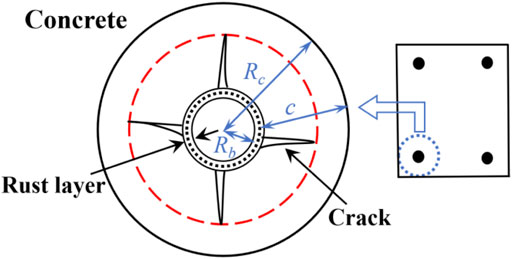
FIGURE 1. Concrete cover cracking evolution model caused by rebar corrosion.
The linear softening model of cracking concrete, described in Chen (2018), is adopted in the present study to quantify the crack growth in the concrete cover surface. In the linear softening model, the actual crack width wc(X) on the concrete surface is estimated by the radial displacement ūb, expressed as
where Wu is the normalized value of the ultimate cohesive crack width, it could be evaluated from the maximum aggregate size of concrete materials, with typical values of Wu = 0.1–0.3 mm (fib, 2010); Gf is the fracture energy of concrete; ft is tensile strength of intact concrete; Ec is modulus of elasticity for intact concrete, and coefficients ƞw and ƞc are defined, respectively, as
where l0 is defined as l0 = ncWulch/(2π), in which lch is characteristic length lch = EcGf/ft2; and the total number of the cracks in the cover is estimated from nc≈2πRc/Lc, in which the spacing of crack bands Lc is approximately three times the maximum aggregate size; Rc = Rb + c, in which Rb is the radius of reinforcement, and c is the concrete cover thickness. The crack width coefficient δ(Rc, Rb) is defined as
The corrosion-induced concrete cracking caused by the rust expansion often propagates with multiple cracks simultaneously, and the cumulated crack width w over the cover can be calculated by w = ncwc(X).
As a major part of bearing the compressive loads, the reduction of the concrete cover may significantly affect the residual bearing capacity of the corrosion-damaged RC columns, as shown in Figure 2. In this paper, the damaged concrete cross-sectional area of the corroded column is simplified in calculations by adopting the equivalent rectangular cross-section, as shown in Figure 2B.
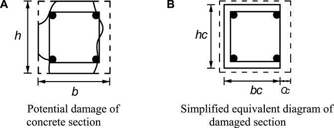
FIGURE 2. Reduction of concrete cross-sectional area of corroded RC columns.
Based on the simplified equivalent rectangular cross-section, the residual size of the corrosion-damaged concrete cross-section can be calculated from the crack width of the concrete surface w, namely
where cc is the loss of the concrete cover thickness after corrosion damage; T is estimated from the load-carrying capacity test of the corroded RC column, which is the total crack width on the concrete surface when the concrete cover is completely spalling, taken here as T = 0.003m (Hui et al., 1997); hc and bc are residual depth and width of the concrete cross-section, respectively; h and b are the original depth and width, respectively; cl, cr, cu and cd are the loss of the concrete cover thicknesses on the left, right, upper and lower sides of the concrete cross-section, respectively, obtained from Eq. 9. In addition, it is worth noting that the loss of the concrete cross-section will also cause the change of the height of the concrete compression zone.
Many factors, including the capacity deterioration of rebar, the poor performance of the rust layer, and the cracking and spalling of the concrete, largely affect the structural strength of RC columns. With the combined action of rebar corrosion and concrete cracking, the bond strength of the tensile rebar and the surrounding concrete degrades. When the rebar anchorage failure occurs before the tensile rebar yielding, the incompatibility of the stress-stain relationship between the rebar and the surrounding concrete needs to be considered. In addition, the probability of buckling of the compressive steel bars gradually increases due to the concrete spalling and the steel stirrup corrosion. In this section, the deterioration models of structural strength are constructed based on the deterioration models of the RC materials.
The intact bond strength between the rebar and the surrounding concrete is the key factor to ensure that the steel bars and the concrete work together. With the progression of rebar corrosion, the rebar bond strength may experience a significant decline caused by the rust expansion and the cracking and spalling of the concrete, and then maintain a reduced value due to the confinement from the steel stirrups around the longitudinal rebar. Chen (2018) provides a simplified model to estimate the rebar bond deterioration by considering the effect of the stirrups and the concrete cracking. The simplified model proposed by Chen (2018) is adopted here to estimate the residual bond strength τux, expressed here as
where ζ(X) is the residual bond strength ratio; τu0 is the ultimate bond strength of the rebar with intact concrete, and λη is the coefficient estimated from rebar bond strength experiment taken as λη = 15–20 (Cairns et al., 2006). In general, the deformed bars have greater residual bond strength than plan bars. For RC columns with a relatively high corrosion level, the failure modes of tensile rebar may shift from yielding in tension to rebar bond failure due to the insufficient bond strength. When the rebar anchorage failure occurs before the tensile rebar yielding, its bearing capacity with bond deterioration Fux can be determined by the residual bond strength, and then the load-carrying capacity of the steel bar is rewritten from Eq. 3 as
where la is the development length, and Dc is the residual diameter of the corroded rebar, calculated from Dc= Db(1-X)0.5. When the rebar bond strength is intact, the stress-strain relationship between the tensile rebar εsx and the surrounding concrete εsc is consistent, i.e., εsx = εsc. After rebar bond failure, the corroded rebar may slip after the load, and the strain of the concrete εsc could be greater than the strain of the rebar εsx, i.e., εsc > εsx. Here, the interpolation factor G(X) is introduced to establish a new deformation coordination equation between the tensile rebar and the concrete after bond loss, i.e., εsc = εsx/G(X) (0 ≤ G(X) ≤1), where the factor G(X) (Wang and Liu, 2009) is estimated from
where the initial and final strains are taken as εstart = 0.002, εend = 0.006, respectively (Ho et al., 2004); Yx is the compression zone height of the concrete cross-section; Leq is the length of the equivalent plastic section (Daniell et al., 2008); Lsoft is the length of the equivalent softened section, and Lub is the unbonded length of the tension steel bar. Thus, the strain relationship between the steel bar and the concrete becomes εsx= G(X)εsc.
The intact concrete and uncorroded steel stirrups provide supports for the longitudinal rebar to fully bear the loads. In general, the corrosion level of steel stirrups is often greater than that of longitudinal bars due to the thinner concrete cover of the steel stirrups (Wang and Liang, 2008). With the growth of corrosion, the probability of buckling failure of the longitudinal rebar increases due to the stirrup corrosion and the concrete cover spalling. Therefore, the residual bearing capacity of the corroded longitudinal rebar in compression can be determined by the smaller value of the rebar yield strength and buckling strength. The critical buckling stress fcr can be obtained by using Euler’s formula, namely
where the inertia moment of the corroded reinforcement Isc is calculated from Isc=πDc4/64; Esc is the elastic modulus of the corroded longitudinal bars, and the initial value Es can be taken since rebar corrosion has no obvious effect on the elastic modulus; Lexp is the laterally unbraced length of the structural member taken as Lexp = ns, in which s is the stirrup spacing, and n is the order of the compressed longitudinal rebar if the deformation of the corroded steel bar crosses (n-1) stirrups.
For an eccentrically loaded RC column, as shown in Figure 3, the structural member is subjected to the combined action of axial load N and bending moment M. In general, the failure types of eccentrically loaded columns can be divided into two groups by the transition eccentric distance ej, i.e., large eccentric compression failure (e > ej) and small eccentric compression failure (e < ej). According to the degradation models of materials and structural strength, the residual compression zone height of the concrete cross-section and the bearing capacity deterioration of the corrosion-damaged RC columns under small eccentric compression are discussed in this section. At the early stage of corrosion, the effect of key factors, such as the loss of rebar yielding strength and cross-section area, concrete cracking, and the change of concrete compression zone height, on the bearing capacity of the columns should be taken into account. With the progression of corrosion, the influence of critical factors, such as the incompatibility between the rebar and the surrounding concrete, concrete cover spalling, and rebar buckling, on the bearing capacity of the corroded columns needs to be considered. Here, the residual bearing capacity Nux of the corroded eccentrically loaded RC columns with small eccentricities is analyzed based on the degradation models of materials and structural strength, expressed here as.
where a1 is the coefficient taken as 1 (fib, 2010); Yx is the compression zone height of the concrete column obtained from Yx= yx/β1, in which β1 is the coefficient taken here as 0.9 (fib, 2010); yx is the equivalent compressive zone of the concrete; h is original depth of the concrete cross-section; bc is residual width of the concrete cross-section after concrete cover cracking, calculated from Eq. 10; fc is the concrete compressive strength; Fszx and Fsx are the bearing capacities of the near loading side rebar and the far loading side rebar, respectively; e is the eccentricity of the applied load defined as e = e0+ea, in which ea is the additional eccentricity and e0 is the load eccentricity; h0 is the effective depth of the column given by h0 = h-as, in which as and a’s are the distances from the centroid of the far loading side rebar and the near loading side rebar to edge of the concrete cover, respectively; xc is the average loss of the concrete height in the compression zone taken as xc = cu, in which cu is calculated from Eq. 9; εc is the strain of compressive concrete (εc≤εcu), and εcu is the ultimate compressive strain of the concrete (fib, 2010).
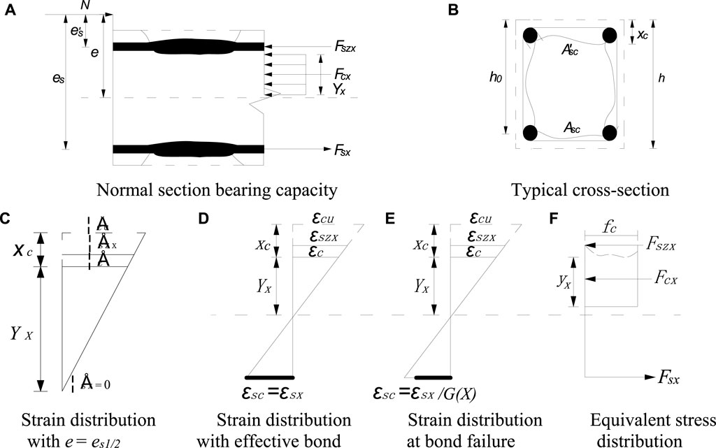
FIGURE 3. Applied forces and stress distribution diagram of the cross-section of the corroded RC column and its parameter definitions.
In the case of the eccentricity e = 0, the RC columns bear the concentric compressive load, and the whole concrete cross-section is in compression. Therefore, the concrete compression zone height Yx(X) is estimated from the residual height of the concrete cross-section, taken as Yx(X) = hc. The residual bearing capacity of all steel bars affected by corrosion is governed by the smaller values of the rebar yield strength and buckling strength, namely
where fyc and f’yc are the residual yield strengths of the far loading side rebar and the near loading side rebar, respectively; Asc and A’sc are the residual cross-sectional areas of the far loading side rebar and the near loading side rebar, respectively; fcr is the critical buckling stress of rebar, calculated from Eq. 14. Consequently, the bearing capacity Nux of the corroded concentrically loaded columns can be calculated in Eq. 15 by using the rebar capacity and the compression zone height of the concrete given above.
In the case of the RC columns under small eccentric compression (0 < e < ej), the near loading side rebar yields under compression, and the far loading side rebar may be in tension or in compression. By calculating the residual bearing capacity of the steel bars and the compression zone height of the concrete cross-section Yx(X), the residual capacity of the corroded columns Nux with the corresponding eccentricity e can be obtained. In order to accurately analyze the loading condition of the far loading side rebar, the transition condition of small eccentrically loaded columns should be considered here, i.e., e = es1/2.
In the case of e = es1/2, the rebar bearing capacity Fsx becomes Fsx = 0. Meanwhile, the near loading side rebar yields under compression, and the bearing capacity of the steel bars Fszx can be obtained from Eq. 17. According to the stress-strain relationship shown in Figure 3C, the concrete compression zone height can be defined as Yx(X) = h0-xc, and then the critical eccentricity of the RC column with small eccentricity es1/2 can be calculated from
Based on the transition condition of small eccentrically loaded columns, two cases are discussed in detail: 1) 0<e < es1/2, i.e., far loading side rebar under compression; 2) es1/2<e < ej, i.e., far loading side rebar in tension.
In the case of 0<e < es1/2, all steel bars of the column are under compression. The strains of the near loading side rebar εszx and the far loading side rebar εsx can be expressed as
Based on the stress-strain relationship and the stress state of the rebar, the residual bearing capacity of the near loading side rebar Fszx can be also calculated from Eq. 17, and the residual bearing capacity of the far loading side rebar Fsx can be rewritten as
In the case of es1/2<e < ej, the near loading side rebar is under compression, and its residual capacity Fszx can be evaluated from Eq. 17, and the far loading side rebar is in tension. In the early stage of rebar corrosion, the stress-strain relationship between the tensile rebar and the surrounding concrete is nearly consistent due to the effective rebar bond strength. However, due to rebar bond strength deterioration, the rebar anchorage failure occurs before the tensile rebar yielding, which causes incompatibility of the stress-strain relationship between the far loading side steel bars and the surrounding concrete. Thus, when es1/2<e < ej, two cases, i.e., effective rebar bond and rebar bond failure, should be considered.
In the case with effective rebar bond, the far loading side rebar is in tension, and the capacity of the corrosion-damaged rebar on this side can be obtained from the consistent strain relationship due to the effective bond of the tensile rebar. According to the consistent strain relationship shown in Figure 3D, the rebar strains of the near loading side εszx and the far loading side εsx can be expressed as
Then, the bearing capacity of the steel bars away from the axial load Fsx is expressed by
In the case of rebar bond deterioration, when the rebar corrosion reaches a high level, the concrete strain εsc is greater than the rebar strain εsx on the far loading side, as shown in Figure 3E. The new deformation compatibility equation between the tensile rebar and the surrounding concrete can be obtained by introducing the interpolation factor G(X), namely εsc = εsx/G(X). Then, the strain relationship between the near loading side rebar εszx and the far loading side rebar εsx is modified here as
where
In conclusion, when 0<e < ej, the residual bearing capacity of the corroded steel bars can be calculated by combining the degradation models of RC materials and structural strength and the stress-strain relationship. Consequently, the bearing capacity of the corrosion-damaged columns Nux can be evaluated by substituting the rebar bearing capacity and the eccentric distance e into Eqs 15, 16.
The performance deterioration of RC structures develops with time due to the combined action of many factors, such as operation environments and load conditions. However, these factors are usually uncertain, which leads to the randomness of the performance degradation process of in-service RC structures. In order to accurately evaluate the failure probability and residual life of existing RC structures, it is necessary to select appropriate stochastic deterioration models and random variables of the corroding structures (Chen, 2018). In the stochastic deterioration modeling, the value of the allowable deterioration limit is determined by the service environments and requirements. After a certain indicator of the structure degrades to the allowable deterioration limit, the structure is considered as failure. For the corroding RC structure, the corrosion-induced concrete crack width and bearing capacity deterioration rate is often chosen as the random variables for the stochastic deterioration model because of their uncertainties in development with time (Chen and Alani, 2013; Chen and Nepal, 2020).
As a stochastic process with independent and non-negative increments, the gamma process is suitable for simulating the progressive damage accumulation over time. The gamma process has been widely used for probabilistically undertaking structural performance assessment and remaining life prediction (Van Noortwijk, 2009). Based on the definition of the gamma process (Van Noortwijk and Frangopol, 2004), the probability density function (PDF) of the random variable S can be expressed as
where λ is the scale parameter with λ > 0 and can be estimated from the maximum likelihood method by maximizing the logarithm of the likelihood function of the increment of the parameter (Edirisinghe et al., 2013), and
in which ƞ(t) is the shape function and can be calculated from the expected random variable S over time t, given by
According to the serviceability and durability requirements of the corroded RC structures, the crack width on the concrete surface can be chosen here as the random variable for the gamma process, taken here as
where the concrete crack width w can be estimated by the equation given in Section 2, and wl is the allowable crack width of the concrete surface with a typical value of wl = 0.3 mm for aggressive environments. By considering the ultimate limit state requirements of the corroded RC columns, the bearing capacity deterioration rate is selected here as random variable for the gamma process, namely
where Nu0 is the ultimate bearing capacity of intact RC columns; Nux is the residual bearing capacity of the corrosion-damaged RC columns, discussed in Section 4; Nul is the allowable deterioration value of the corroded RC columns.
In order to predict the lifetime structural performance deterioration process from time 0 to T (T > 0), the gamma sequential sampling (GSS) approach (Avramidis et al., 2003) is utilized here for simulating the stochastic growth process in concrete cracks and the bearing capacity deterioration rate. First, the period between 0 and T is equally divided into a series of time, 0, t1, t2, …,tn-1, tn, and tn = n∆T = T, where n is a positive integer and ∆T is the fixed time interval. Then, the increment δi of the random variable S at each time interval follows the character of the gamma distribution, i.e., δi ∼ Ga (δ| ƞ(ti)- ƞ(ti-1), λ). And the cumulative increment by gamma process at time ti can be calculated from S(ti) = ∑δi.
Assuming that the concrete crack width and the bearing capacity deterioration rate of the corroding RC structures reach the corresponding deterioration limit Sl at time Tf, the failure probability associated with the serviceability and ultimate limit state requirements can be obtained from the gamma density function in Eq. 26, expressed as
where
where
The given allowable limit Sl of the chosen random variable S has a significant influence on the remaining life Trul of the corroding RC structures.
A typical corroded RC column, described in Wang and Liang (2008), is now used to demonstrate the effectiveness of the proposed methods. In the given experiments, partially corroded RC columns under eccentric loading were investigated, where the partial corroded lengths Lub were 350 and 700 mm, respectively, and the eccentric distance of 50 mm was chosen for the corroded RC columns to represent the applied load with small eccentricity. The design details of the corroded RC columns tested by Wang and Liang (2008) are shown in Figure 4. The specimens had a length of l = 1,300 mm, with a rectangular cross-section of height h = 200 mm and width b = 200 mm. Two steel bars of a diameter of 18 mm were embedded into the far loading side and near loading side of the column, respectively, with the yield strength of fy0 = 397.5 MPa and the modulus of elasticity Es = 200 GPa. The stirrups consisted of the plain steel bar with a diameter of 8 mm, spacing at 100 mm in the center part. The concrete columns had an average clear cover thickness of 30 mm, with the average actual compressive strength of fc = 41.5 MPa. By assuming that the loading point during the test is accurate and the structural quality is consistent, the additional eccentricity can be taken as ea = 0. The RC columns were short ones with the assumption of without initial imperfection for compression, and the second-order effect on the RC column can be ignored.
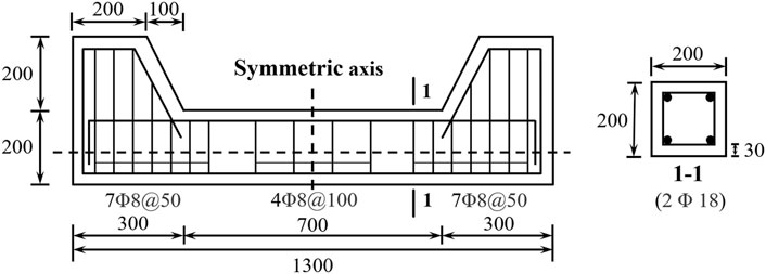
FIGURE 4. Design details of the corroded RC columns tested by Wang and Liang (2008) (dimensions in mm).
The RC material and structural strength degradation models proposed in this paper are employed for the tested RC columns. According to the test data available, the parameters required for the proposed models are estimated by using the relevant method (fib, 2010; Chen and Alani, 2013), summarized in Table 1.
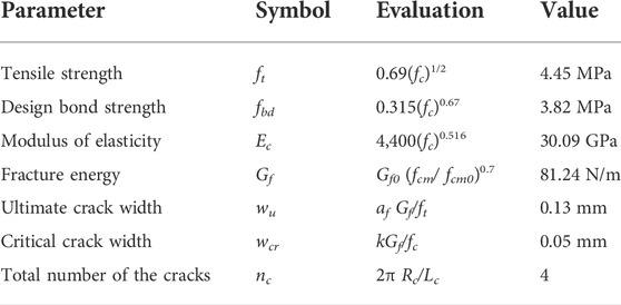
TABLE 1. Estimated parameters of concrete materials.
The predicted results in Figure 5 are the propagation of the crack width on the concrete surface as corrosion level increases. The predicted results are compared with the experimental data from various studies (Alonso et al., 1998; Vidal et al., 2004; Coronelli et al., 2013; Banba et al., 2014; Khan et al., 2014). From the results in Figure 5, the crack appears on the concrete cover surface at the corrosion level of nearly 1%, and the predicted crack width reaches approximately 0.3 mm at the corrosion level of 4%.
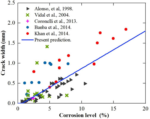
FIGURE 5. Predicted crack width on the concrete surface versus rebar corrosion level, compared with experimental data available from various sources.
In Figure 6, the stochastic growth process of the concrete cracks is simulated by gamma sequence sampling (GSS), where the value of scale parameter λ is assumed to be 1, 10, 20, and 50, respectively. The simulated crack width growth is then compared with the predicted results from the proposed crack width evolution model. From the results, the simulated process of concrete crack growth consists of a series of small growth segments with different lengths, and generally matches the predicted results from the proposed model, especially in the cases with the scale parameter λ = 20.
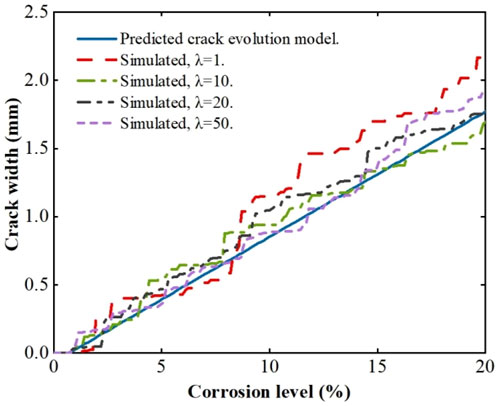
FIGURE 6. Simulated concrete crack growth process by gamma sequence sampling (GSS) with various values of scale parameter λ, compared with the predicted concrete crack width evolution.
The failure probability of the corrosion-induced concrete cracking is modelled by the gamma process, where the crack width on the concrete cover surface is selected as a random variable for evaluating the serviceability and durability of the corroded RC structures. The results of the failure probability as a function of corrosion level are shown in Figure 7 for different values of allowable crack width on the concrete cover, where allowable crack width ranges from 0.2 to 0.6 mm. As expected, with the development of rebar corrosion, the failure probability associated with concrete cracking increases for any given allowable limit. By comparing with the larger value of allowable crack width, the failure probability increases more rapidly for the smaller limit of allowable crack width. The failure probability reaches 50% when the predicted crack width equals the given value of allowable crack width.
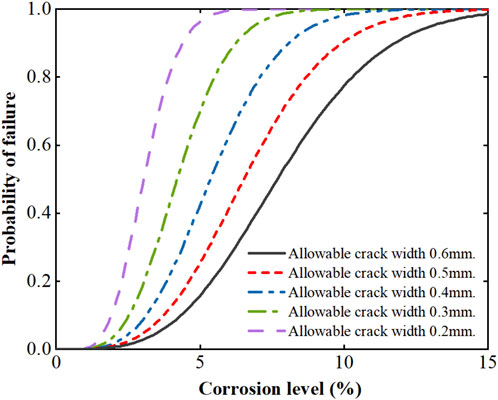
FIGURE 7. Failure probability associated with concrete cracking evolution for various allowable crack width limits.
Figure 8 shows the results for the predicted remaining life over time associated with the corrosion-induced concrete cracking, where the remaining useful life of the RC structure is related to the serviceability requirements. In Figure 8, to investigate the effect of corrosion rate on the failure probability of the corroded RC structure, various values of corrosion rate are adopted, corresponding to the low-to-high corrosion intensities, i.e., 0.3, 0.5, 1, 3, 5 uA/cm2, and the allowable crack width is taken as 0.3 mm. The results of the remaining service life over the elapsed time are shown in Figure 9 for different allowable limits ranging from 0.2 to 0.6 mm in the case with icorr = 1 uA/cm2. From the obtained results, the remaining service life of the corrosion-damaged structures largely depends on the service environment and the allowable crack width on the concrete cover surface. At the corrosion rate icorr of 1 uA/cm2, the remaining service life is estimated as 1.1 years at the age of 20 years when the allowable crack width is taken as 0.3 mm.
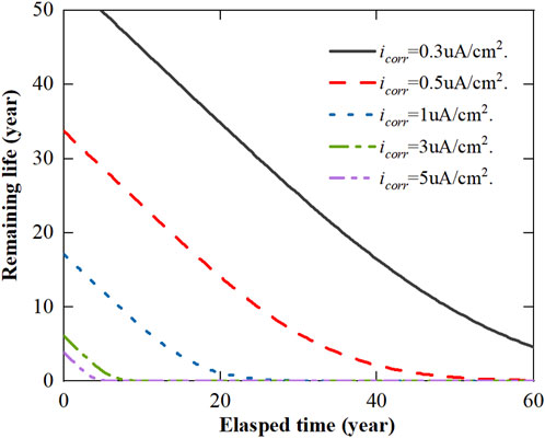
FIGURE 8. Predicted remaining useful life over time due to corrosion-induced concrete cracking with various corrosion rates.
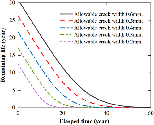
FIGURE 9. Predicted remaining useful life over time due to corrosion-induced concrete cracking with various allowable crack width limits.
In Table 2, the residual load capacity of the corroded RC columns is estimated from the proposed models and compared with the experimental results given by Wang and Liang (2008). From the obtained results, the relative error (Ncal-Nexp)/Nexp ranges from −0.056 to 0.174, with a mean absolute value of 0.073 and a variance of 0.0099, indicating good agreement with the experimental results. In general, the predicted results are slightly larger than the test results, which are probably caused by the inaccurate measurement of loading point and the variation of concrete compressive strength.
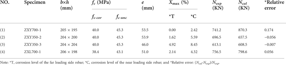
TABLE 2. Comparison of the predicted residual load capacity of the corroded RC column with experimental data available.
From the results obtained above, the moment-axial force (M-N) interaction curves of the corroded RC column at various corrosion levels are investigated, and then compared with the experimental data in Wang and Liang (2008) and the calculated results in Tapan and Aboutaha (2011), as shown in Figure 10. The present results of the M-N interaction diagram at various corrosion levels appear better in agreement with the existing experimental data, which is mainly due to the improved models with considering concrete cross-section area reduction and concrete compression zone height variation. From the results, the bearing capacity of the corroded RC column under axial compression (e = 0) and small eccentricity compression (e < ej) decreases significantly at the corrosion level between 0–10%, which is caused by the loss of the concrete cross-section and the decrease in the concrete compression zone height.
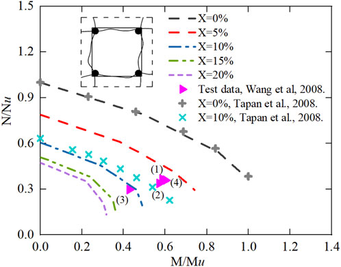
FIGURE 10. M-N interaction diagram for the corroded RC column at various corrosion levels.
The results in Figure 11 show the stochastic deterioration process of the bearing capacity of the corrosion-damaged RC columns based on the Gamma sequence sampling (GSS), where the value of scale parameter is taken as 1.0, 10.0, 20.0, and 50.0, respectively. The results of the stochastic deterioration process of the corroded RC columns with the eccentricities e = 0, 50, and 80 mm are given, respectively, and compared with the calculated results from the proposed models. When the corrosion level reaches 6%, the residual bearing capacity of the corroded RC columns reduces to about 25%, 31%, and 34% of its original ultimate capacity for the eccentricities of e = 0, 50, and 80 mm, respectively. From the results, the bearing capacity deterioration of the corroded RC column is more significant in the case of relatively large values of the eccentricities. As shown in Figure 11, the simulated bearing capacity deterioration rate growth generally matches the predicted results from the proposed model with a better agreement in the cases with the scale parameter λ = 10 and 20.
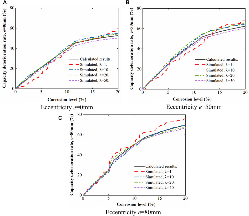
FIGURE 11. Simulated bearing capacity deterioration rate growth by gamma sequence sampling (GSS) with various values of scale parameter λ and different eccentricities.
From the predicted results of the bearing capacity deterioration, the failure probability of the corroded RC columns with various eccentricities, i.e., e = 0, 50, 80 mm, is obtained for different allowable deterioration limits Nul, as shown in Figure 12. The allowable deterioration limits represent the thresholds of the capacity deterioration for the ultimate limit state requirements, and three cases with the allowable deterioration limits of 0.2Nu0, 0.3Nu0, and 0.4Nu0 are considered here. From the obtained results, both the eccentric distance and the allowable deterioration limit have a significant influence on the failure probability of the corroded RC columns. As expected, with rebar corrosion development, the probability of failure increases faster for the smaller value of allowable deterioration limit and the larger value of the eccentricity. Furthermore, the failure probability has a shape increase at the corrosion level of approximately 6% in Figures 12B,C, mainly due to the bond strength loss of the tensile rebar.
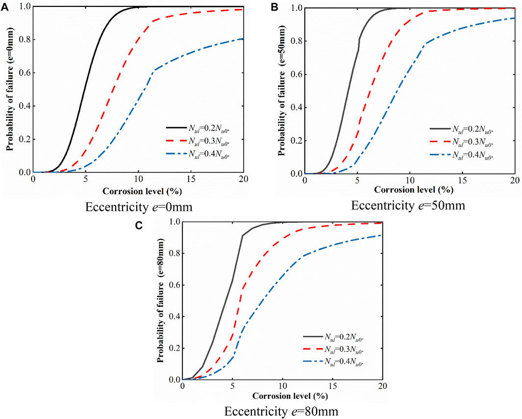
FIGURE 12. Predicted failure probability of the corroded RC columns under different loading conditions for various allowable deterioration limits Nul.
From the obtained failure probability of the corroding columns, the remaining useful life associated with the bearing capacity deterioration is investigated, where the allowable deterioration limit Nul ranging from 0.2Nu0 to 0.4Nu0 and corrosion rate of 1 uA/cm2 are considered. Here, the remaining useful life is predicted for the columns under various loading conditions, including eccentricity e = 0, 50, and 80 mm, as shown in Figure 13. From the results, the remaining useful life of the corrosion-damaged RC columns largely depends on the given allowable deterioration limit. In the case with the allowable deterioration limit of Nul = 0.3Nu0, the remaining useful life of the corroded column with an eccentricity of e = 0 mm is about 16 years if the structure is still surviving at age of 20 years, while the remaining useful life of corroded column with eccentricities of e = 50 and 80 mm is approximately 10 and 7 years, respectively.
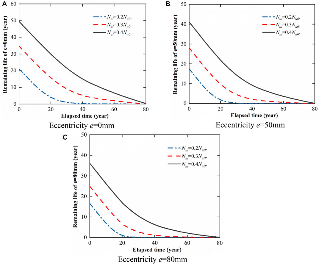
FIGURE 13. Estimated remaining life of the corroding columns under different loading conditions for various allowable deterioration limits Nul.
To investigate the effect of corrosive environments on the remaining useful life associated with the bearing capacity deterioration, various values of the corrosion rate are selected with the allowable deterioration limit of 0.3Nu0, where the corrosion rate is taken as 0.3, 0.5, 1, 3, and 5 uA/cm2, respectively, as shown in Figure 14. Meanwhile, three cases of eccentricities are chosen to demonstrate the influence of the eccentric distance on the remaining useful life of the corroded columns, i.e., e = 0, 50, 80 mm, respectively. From the results in Figure 14, the corrosive environments and the eccentric distance of the RC column significantly affect the remaining useful life of the structure. The remaining useful life has a sharper drop when the corrosion rate becomes higher. In Figure 14A, due to the loss of concrete cross-section area and the reduction of rebar capacity, the remaining useful life of the corrosion-damaged concentrically loaded column decreases to about 8 years if the structure still survives after 60 years in the case with corrosion rate of 0.5 uA/cm2. By comparing with the concentrically loaded column, the remaining useful life of the eccentrically loaded RC column has a lower value at the same corrosion rate, mainly due to the various damage evolutions under different loading. For the eccentric distance of e = 50 and 80 mm, the remaining useful life of the corroded columns at the age of 60 years is all about 5 years, indicating the influence of loading condition.
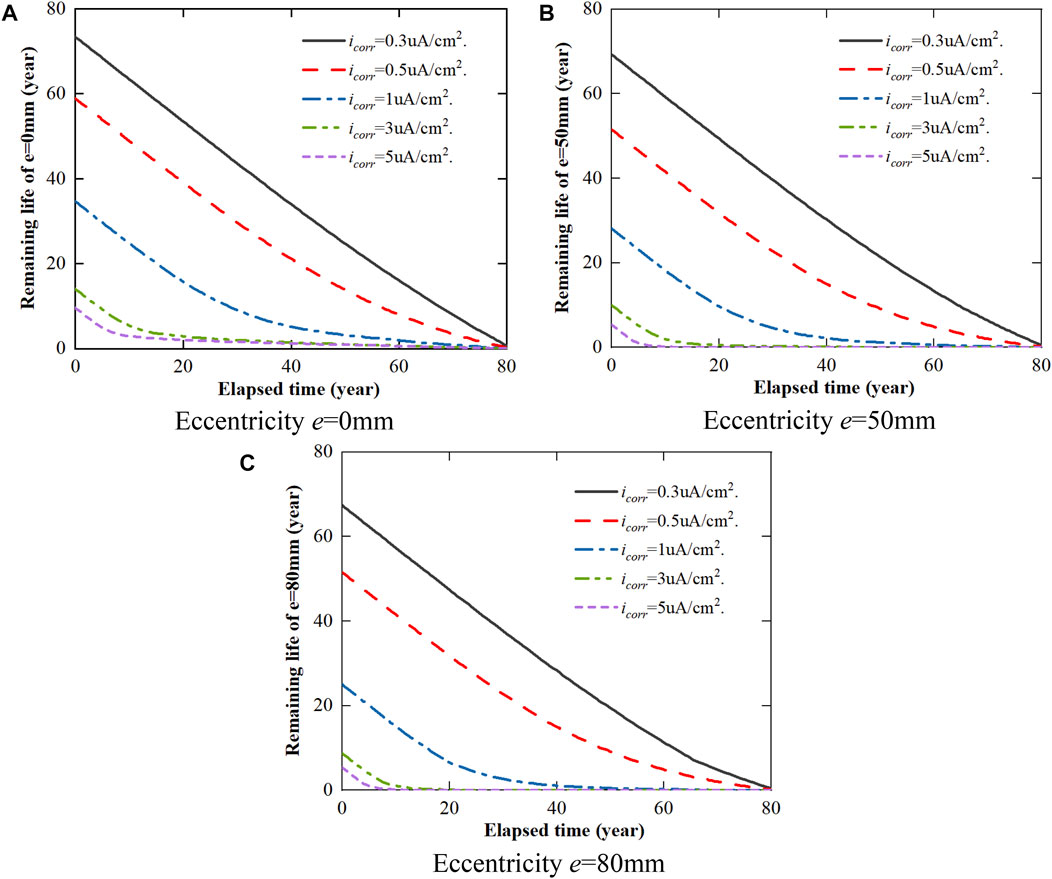
FIGURE 14. Estimated remaining useful life of the corroded column under different loading conditions for various corrosion levels.
This paper presents an effective model for residual bearing capacity assessment and lifetime performance prediction of the corroded RC columns. The degradation mechanism of steel bars and concrete materials due to rebar corrosion is analyzed, and the material degradation models and the structural strength degradation models are proposed. The load-carrying capacity of the corroded RC columns is estimated for various cases of loading conditions. On the basis of the serviceability limit and ultimate state limit requirements, the lifetime performance of the corrosion-damaged RC columns is assessed by stochastic gamma process. Finally, the proposed model for estimating the residual bearing capacity of the corrosion-damaged RC columns is verified by experimental data available, and the failure probability and remaining useful life are predicted for the corroding RC columns. On the basis of the results obtained from the numerical example, the following conclusions can be drawn:
1) At the same corrosion level, greater load eccentricity leads to a sharper deterioration in the load-carrying capacity of the corroded RC columns, i.e. the column bearing capacity deterioration rate under large eccentricity is more severe than that with small eccentricity;
2) The lifetime performance of the corroded RC columns can be significantly affected by many factors, including concrete cover cracking and spalling, the reduction of rebar bearing capacity, the inconsistent of the stress-strain relationship between the rebar and the surrounding concrete, and the change of the compression zone height of the concrete cross-section;
3) The crack width on the concrete surface and the bearing capacity deterioration of RC columns caused by rebar corrosion are the key performance indicators, and can be adopted as random variables for structural performance deterioration assessment of the corrosion-damaged RC columns;
4) For the corroding RC columns, the gamma process is appropriate for evaluating failure probability and estimating the remaining useful life, and could be further used to determine the optimal repair time and cost-effective maintenance strategy.
The original contributions presented in the study are included in the article/Supplementary Material, further inquiries can be directed to the corresponding author.
H-PC: Theoretical development, methodology, supervision, funding support; YJ: Software development, theory, validation, analysis; LX: Data collection, analysis; JL: Data collection. All authors contributed to the article and approved the submitted version.
The authors are very grateful for the financial supports received from the National Key Research and Development Program of China (Grant No. 2021YFE0105600), the National Natural Science Foundation of China (Grant No. 51978263) and the Key Project for Scientific and Technological Cooperation Scheme of Jiangxi Province (Grant No. 20212BDH80022).
The authors declare that the research was conducted in the absence of any commercial or financial relationships that could be construed as a potential conflict of interest.
All claims expressed in this article are solely those of the authors and do not necessarily represent those of their affiliated organizations, or those of the publisher, the editors and the reviewers. Any product that may be evaluated in this article, or claim that may be made by its manufacturer, is not guaranteed or endorsed by the publisher.
Alonso, C., Andrade, C., Rodriguez, J., and Diez, J. M. (1998). Factors controlling cracking of concrete affected by reinforcement corrosion. Mat. Struct. 31, 435–441. doi:10.1007/bf02480466
Avramidis, A. N., L’Ecuyer, P., and Tremblay, P. A. (2003). “Efficient simulation of gamma and variance-gamma processes,” in Proceedings of the 2003 Winter Simulation Conference, 2003, 07-10 December 2003 (Piscataway, NJ: IEEE).
Balestra, C. E. T., Nakano, A. Y., Savaris, G., and Medeiros-Junior, R. A. (2019). Reinforcement corrosion risk of marine concrete structures evaluated through electrical resistivity: Proposal of parameters based on field structures. Ocean. Eng. 187, 106167. doi:10.1016/j.oceaneng.2019.106167
Banba, S., Abe, T., Nagaoka, K., and Murakami, Y. (2014). Evaluation method for bond-splitting behavior of reinforced concrete with corrosion based on confinement stress of concrete against corrosion expansion. J. Adv. Concr. Tech. 12 (1), 7–23. doi:10.3151/jact.12.7
Biswas, R. K., Iwanami, M., Chijiwa, N., and Uno, K. (2020). Effect of non-uniform rebar corrosion on structural performance of RC structures: A numerical and experimental investigation. Constr. Build. Mat. 230, 116908. doi:10.1016/j.conbuildmat.2019.116908
Cairns, J., Du, Y., and Law, D. (2006). Residual bond strength of corroded plain round bars. Mag. Concr. Res. 58 (4), 221–231. doi:10.1680/macr.2006.58.4.221
Chen, H.-P., and Alani, A. M. (2013). Optimized maintenance strategy for concrete structures affected by cracking due to reinforcement corrosion. ACI Struc. J. 110 (2), 229–238. doi:10.14359/51684403
Chen, H.-P., and Nepal, J. (2020). Load bearing capacity reduction of concrete structures due to reinforcement corrosion. Struct. Eng. Mech. 75 (4), 455–464. doi:10.12989/SEM.2020.75.4.455
Chen, H.-P., and Nepal, J. (2018). Modeling residual flexural strength of corroded reinforced concrete beams. ACI Struct. J. 115 (6), 1625–1635. doi:10.14359/51702232
Chen, H.-P. (2018). Residual flexural capacity and performance assessment of corroded reinforced concrete beams. J. Struct. Eng. 144 (12), 04018213. doi:10.1061/(asce)st.1943-541x.0002144
Chen, H.-P., and Xiao, N. (2012). Analytical solutions for corrosion-induced cohesive concrete cracking. J. Appl. Math. 2012, 1–25. doi:10.1155/2012/769132
Choe, D. E., Gardoni, P., and Rosowsky, D. (2010). Fragility increment functions for deteriorating reinforced concrete bridge columns. J. Eng. Mech. 136 (8), 969–978. doi:10.1061/(asce)em.1943-7889.0000147
Chong, Cao., Cheung, M. M. S., and Chan, B. Y. B. (2013). Modelling of interaction between corrosion-induced concrete cover crack and steel corrosion rate. Corros. Sci. 69, 97–109. doi:10.1016/j.corsci.2012.11.028
Coronelli, D., Hanjari, K. Z., and Lundgren, K. (2013). Severely corroded RC with cover cracking. J. Struct. Eng. 139 (2), 221–232. doi:10.1061/(asce)st.1943-541x.0000633
Daniell, J. E., Cehlers, D. J., Griffith, M. C., Mohamed Ali, M., and Ozbakkaloglu, T. (2008). The softening rotation of reinforced concrete members. Eng. Struct. 30 (11), 3159–3166. doi:10.1016/j.engstruct.2008.04.023
Domaneschi, M., Pellecchia, C., De Iuliis, E., Cimellaro, G., Morgese, M., Khalil, A., et al. (2020). Collapse analysis of the Polcevera viaduct by the applied element method. Eng. Struct. 214, 110659. doi:10.1016/j.engstruct.2020.110659
Du, Y. G., Clark, L. A., and Chan, A. H. C. (2005). Residual capacity of corroded reinforcing bars. Mag. Concr. Res. 57 (3), 135–147. doi:10.1680/macr.2005.57.3.135
Edirisinghe, R., Setunge, S., and Zhang, G. M. (2013). Application of gamma process for building deterioration prediction. J. Perform. Constr. Facil. 27 (6), 763–773. doi:10.1061/(asce)cf.1943-5509.0000358
fib (2010). Fédération international du Béton/international federation for structural ConcreteModel code 2010. Lausanne, Switzerland. Federation internationale du beton.
Goksu, C., Inci, P., and Ilki, A. (2016). Effect of corrosion on bond mechanism between extremely low-strength concrete and plain reinforcing bars. J. Perform. Constr. Facil. 30 (3), 04015055. doi:10.1061/(asce)cf.1943-5509.0000811
Ho, J., Kwan, A., and Pam, H. (2004). Minimum flexural ductility design of high-strength concrete beams. Mag. Concr. Res. 56, 13–22. doi:10.1680/macr.2004.56.1.13
Hui, Y. L., Li, R., and Lin, Z. S. (1997). Experimental studies on the property before and after corrosion of rebars in basic concrete members. Ind. Constr. 27 (6), 14–18. doi:10.3321/j.issn:1000-8993.1997.06.004
Imperatore, S., and Rinaldi, Z. (2019). Experimental behavior and analytical modeling of corroded steel rebars under compression. Constr. Build. Mat. 226, 126–138. doi:10.1016/j.conbuildmat.2019.07.109
Khan, I., Francois, R., and Castel, A. (2014). Prediction of reinforcement corrosion using corrosion induced cracks width in corroded reinforced concrete beams. Cem. Concr. Res. 56, 84–96. doi:10.1016/j.cemconres.2013.11.006
Liang, Y. Q., and Wang, L. C. (2020). Prediction of corrosion-induced cracking of concrete cover: A critical review for thick-walled cylinder models. Ocean. Eng. 213, 107688. doi:10.1016/j.oceaneng.2020.107688
Liu, X., Jiang, H., and He, L. (2017). Experimental investigation on seismic performance of corroded reinforced concrete moment-resisting frames. Eng. Struct. 153, 639–652. doi:10.1016/j.engstruct.2017.10.034
Tapan, M., and Aboutaha, R. S. (2011). Effect of steel corrosion and loss of concrete cover on strength of deteriorated RC columns. Constr. Build. Mat. 25 (5), 2596–2603. doi:10.1016/j.conbuildmat.2010.12.003
Van Noortwijk, J. M. (2009). A survey of the application of gamma processes in maintenance. Reliab. Eng. Syst. Saf. 94 (1), 2–21. doi:10.1016/j.ress.2007.03.019
Van Noortwijk, J. M., and Frangopol, D. M. (2004). Two probabilistic life-cycle maintenance models for deteriorating civil infrastructures. Probabilistic Eng. Mech. 19 (4), 345–359. doi:10.1016/j.probengmech.2004.03.002
Vidal, T., Castel, A., and Francois, R. (2004). Analyzing crack width to predict corrosion in reinforced concrete. Cem. Concr. Res. 34 (1), 165–174. doi:10.1016/s0008-8846(03)00246-1
Wang, X. H., and Liang, F. Y. (2008). Performance of RC columns with partial length corrosion. Nucl. Eng. Des. 238 (12), 3194–3202. doi:10.1016/j.nucengdes.2008.08.007
Wang, X. H., and Liu, X. L. (2009). Predicting the flexural capacity of RC beam with partially unbonded steel reinforcement. Comput. Concr. 6 (3), 235–252. doi:10.12989/cac.2009.6.3.235
Xia, J., Jin, W. L., and Li, L. Y. (2016). Performance of corroded reinforced concrete columns under the action of eccentric loads. J. Mat. Civ. Eng. 28, 04015087. doi:10.1061/(asce)mt.1943-5533.0001352
Yalciner, H., Kumbasaroglu, A., El-Sayed, A. K., Balkis, A. P., Dogru, E., Turan, A. I., et al. (2020). Flexural strength of corroded reinforced concrete beams. ACI Struct. J. 117 (1), 29–41. doi:10.14359/51720195
Yu, H. F., Da, B., Ma, H. Y., Zhu, H., Yu, Q., Ye, H., et al. (2017). Durability of concrete structures in tropical atoll environment. Ocean. Eng. 135, 1–10. doi:10.1016/j.oceaneng.2017.02.020
Keywords: RC column, rebar corrosion, concrete cracking, residual bearing capacity, lifetime performance assessment
Citation: Chen H-P, Jiang Y, Xiao L and Liu J (2022) Lifetime reliability analysis of concrete columns damaged by reinforcement corrosion. Front. Mater. 9:926259. doi: 10.3389/fmats.2022.926259
Received: 22 April 2022; Accepted: 06 July 2022;
Published: 15 August 2022.
Edited by:
David M. Bastidas, University of Akron, United StatesReviewed by:
Alper Ilki, Istanbul Technical University, TurkeyCopyright © 2022 Chen, Jiang, Xiao and Liu. This is an open-access article distributed under the terms of the Creative Commons Attribution License (CC BY). The use, distribution or reproduction in other forums is permitted, provided the original author(s) and the copyright owner(s) are credited and that the original publication in this journal is cited, in accordance with accepted academic practice. No use, distribution or reproduction is permitted which does not comply with these terms.
*Correspondence: Hua-Peng Chen, aHAuY2hlbkBlY2p0dS5lZHUuY24=, aHAuY2hlbkBvdXRsb29rLmNvbQ==
Disclaimer: All claims expressed in this article are solely those of the authors and do not necessarily represent those of their affiliated organizations, or those of the publisher, the editors and the reviewers. Any product that may be evaluated in this article or claim that may be made by its manufacturer is not guaranteed or endorsed by the publisher.
Research integrity at Frontiers
Learn more about the work of our research integrity team to safeguard the quality of each article we publish.