 Tao Fu
 Jianpu Hou1
- 1School of Transportation Engineering, Shandong Jianzhu University, Jinan, China
- 2China State Construction Engineering Corporation, Beijing, China
The prefabricated concrete structure is regarded as the main body of the green construction technology, while the joint connection of the prefabricated components is the weak link of force. In addition, the grouting sleeve connection is a widely used connection method in the prefabricated component joints. The effective anchorage of reinforcement is realized by the implementation of a mechanical bite force, friction force and bonding force between reinforcement, grouting material and sleeve inner wall, respectively. Along these lines, in this work, a UHPC-based grouting material was prepared, and its main technical performance was tested. The influence of the grouting mix proportion and anchorage length on the stress performance was thoroughly investigated by carrying out a unidirectional tension test of eight grout-filled splice sleeves. The acquired results show that UHPC grouting containing micro and particles possess high mechanical strength and durability. The incorporation of UHPC grouting containing steel fibers can further improve the compressive and flexural strength. However, its fluidity will be reduced and grouting difficulties will be induced. For that reason, the utilization of UHPC-based grouting material without steel fibers is recommended. The grout-filled splice sleeve joints with UHPC meet also the strength requirements, and the sleeve can be found in the elastic stage in the test, indicating that sleeve joints possess a higher safety margin.
1 Introduction
Prefabricated construction is considered the main development subject of environmental construction. Under the background of industrialization, prefabricated bridge structures arose at the historic moment. Reinforced sleeve grouting connection is one of the widely used connections in prefabricated bridge structures, which is mostly used for the vertical connection of prefabricated components, such as piers and caps (Xu et al., 2021).
Sleeve connection improves the bonding strength between the interfaces by inhibiting the splitting deformation of the internal grouting. The reliability of the sleeve connection strongly depends on the interfacial bond strength between the grouting material and steel bar or sleeve. The working and mechanical performance of the grouting material is closely related to the bond strength, and the affecting factors include cementitious materials, active admixtures, aggregates, additives, and the like (Hayashi et al., 1993; Hayashi et al., 1994; Moosavi et al., 2005; Ling et al., 2014).
Reactive powder concrete (RPC) is considered a kind of ultra-high-performance concrete. Fang (2018) took the sleeve grouting connection as the object, optimized the mix proportion of the RPC grouting material, and made the connection joint specimen for the uniaxial tensile test. On top of that, the influencing factors of the interfacial bond strength were systematically analyzed, the empirical formula of the average bond strength was fitted, and the critical anchorage length of reinforcement in the RPC sleeve was deduced.
Reinforcement in the RPC sleeve was deduced. Shao eta l., (2020) proposed the use of an ultra-high performance concrete UHPC-based grouting material containing steel fiber and ultra-fine quartz sand, whereas the gravity grouting method was used to connect steel bars and sleeves. The extracted results revealed that the sleeve filled with UHPC-based grouting material has good mechanical properties. Based on the Box-Behnken Design analysis method, Li (2019) established a calculation model for the early mechanical properties of grouting materials, and an early-strength ultra-high grouting material was also prepared. This grouting material showed also excellent mechanical properties in the test. He et al. (2018) presented a summary of the results of an experimental investigation to assess the behavior of shear connectors encased in concrete-filled steel cells (CFSCs), which were used in steel-concrete joints with ultra-high performance concrete (UHPC) grout. Fan et al. (2019) mixed lightweight sand (LWS) and steel fibers in UHPC to promote internal curing and improve flexural strength. From the reported outcomes in the literature, it can be argued that steel fiber with a volume content of up to 3% will not lead to corrosion of the steel rebar and thus can be safely used in UHPC.
Sun et al. (2015) used iron tailings instead of quartz sand as an aggregate to prepare cement-based grouting material. The impact of the iron tailings replacement rate, water-cement ratio, and cement-sand ratio on the mechanical properties of the grouting material were studied. The authors demonstrated that a relatively high substitution rate of the iron tailings was detrimental to the working performance of the grouting. The appropriate amount of iron railings can also improve the compressive strength of the grouting material at different ages. More specifically, when the replacement rate was 40%, all kinds of properties of the grouting material met the requirements. Anagnostopoulos et al. (2014) examined the impact of the water-reducing agent on cement-based grouting material. By comparing the influence of polycarboxylate superplasticizer and naphthalene superplasticizer on the various properties of grouting material, the following conclusion can be drawn: the polycarboxylate water reducer had a better performance improvement on grouting materials with water-cement ratios of 0.33, 0.4 and 0.5. Furthermore, the acquired outcomes were improved than that of the naphthalene water reducer, but the polycarboxylate water reducer could increase the final setting time of grouting materials.
Haber et al. (2015) studied the mechanical properties of sleeve connection joints under static, dynamic, and cyclic loading conditions and the load-displacement curves of grouting sleeve precast columns were compared. Yu et al. (2016), Yu et al. (2017), Yu et al. (2021) explored the mechanical mechanism of reinforcement sleeve grouting lap joints by enforcing a uniaxial tensile test. The specimen’s bearing capacity and ductile hoop strain were also investigated. In another interesting work, Wu et al. (2017) carried out stress analysis of the grouting sleeve wall and the calculation formula of the wall stress was provided. The authors demonstrated that with the increase of the diameter of the steel bar, the stress of the tube wall was significantly improved, while the experimental value of the stress of the tube wall was in good agreement with the calculated value. Ling et al. (2014) designed six different types of grouting sleeves by improving the inner wall structure of sleeves and feasibility test research was also carried out. The differences in the mechanical properties of the different types of sleeve connections were compared by the authors. Lu et al. (2019) carried out an experimental study on the mechanical properties of wedge grouting sleeves and wedge thread grouting sleeves. A suitable anchorage length of the steel bars and improvement measures were proposed for improving the tensile strength of wedge sleeve joints.
The grouting material is considered the main force transmission medium of the connection joint. Consequently, its working performance directly affects the reliability of the grouting sleeve connection node, thereby influencing the overall stability and safety of the fabricated structure. Under this direction, in this work, a UHPC-based sleeve grouting material was prepared, and its flexural strength, compressive strength and fluidity were thoroughly investigated. Eight grouting sleeve joint specimens were fabricated by using UHPC as grouting material, whereas the mechanical properties of the connection joint were explored. The load-displacement curve of the connection joint, the strain variation of both sleeve wall and steel bar were obtained, and the influencing factors of the interface bonding strength were analyzed.
2 Preparation and Performance Test OF UHPC-Based Sleeve Grouting Material
2.1 Raw Materials
Based on the principle of minimum compactness, the raw materials used in UHPC-based grouting material configuration are the following:
• Water: tap water;
• Cement: P·O 42.5;
• Silica fume: ultra-high active ultrafine particles, the particle size range of 0.1–0.3 μm, Si O 2 content greater than 90%;
• Quartz sand: spherical particles, the particle size range of 0.18–0.425 mm, Moh’s hardness is 7;
• Fly ash: high active spherical vitreous, particle size is about 1.2 μm;
• Water reducing agent: liquid polycarboxylate superplasticizer;
• Steel fibers: 6 mm × 2 mm copper-plated smooth steel fiber.
The parametric properties of the various components are shown in Table 1 to Table 6.
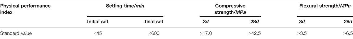
TABLE 1. Physical properties of cement.
The physical properties of cement is shown in Table 1. The physical properties of silica fume is shown in Table 2. The physical properties of quartz sand is shown in Table 3. The physical properties of fly ash is shown in Table 4. The chemical composition of fly ash is shown in Table 5. The physical properties of steel fiber is shown in Table 6.
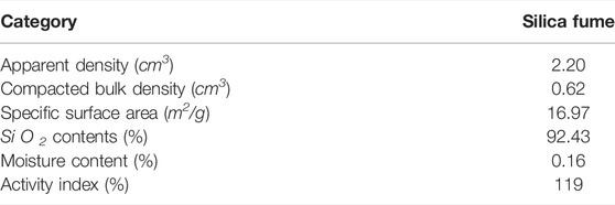
TABLE 2. Physical properties of silica fume.
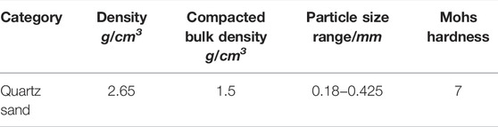
TABLE 3. Physical properties of quartz sand.
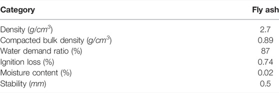
TABLE 4. Physical properties of fly ash.
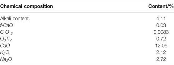
TABLE 5. Chemical composition of fly ash.

TABLE 6. Physical properties of steel fiber.
2.2 Preparation and Performance Test of UHPC-Based Grouting Material
2.2.1 Mix Proportion and Preparation of UHPC-Based Grouting Material
Two UHPC-based grouting materials with different mixing ratios were prepared in the experiment to study the influence of steel fibers on the mechanical properties of UHPC-based grouting material, such as flexural strength, compressive strength, and flowability. They were numbered GA and GB. The GB grouting material was produced by adding a certain proportion of steel fiber on the basis of GA grouting material. When 1 m3 UHPC grouting material was employed as an example, the mix proportion of GA and GB is shown in Table 7.
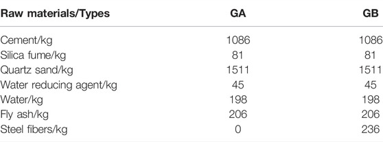
TABLE 7. The mix proportion of UHPC-based grouting materials.
The production steps of the UHPC-based grouting material can be described as follows: the performance test of grouting material was carried out by a hand-held vibration mixer. Before mixing, the mixing shaft should be wetted and wiped without obvious water. Then, the cementitious material and fine aggregate were weighted according to the mix proportion presented in Table 7 and pour it into the mixing barrel to stir evenly. Subsequently, a water-reducing agent was added to most of the water, the residual water was washed with the reducing agent in the beaker with residual water, and then it was poured into the mixing barrel. After stirring evenly again, the steel fibers were added 2—3 times to continue stirring. When the steel fibers were evenly dispersed in the slurry, the preparation of the UHPC-based grouting material was completed.
2.2.2 Performance Test of the UHPC-Based Grouting Material
1) Flexural strength and compressive strength test of the UHPC-based grouting material
The material performance test of the UHPC-based grouting material was carried out based on the Test method of cement mortar strength (ISO method) GB/T17671-1999. The prism specimen with a size of 40 mm × 40 mm × 160 mm was fabricated, and the flexural strength and compressive strength of the specimen were measured.
The flexural strength test of the UHPC-based grouting material was measured by using the flexural strength testing machine. More specifically, the specimen was placed on the supporting cylinder of the testing machine. The long axis of the specimen was perpendicular to the supporting cylinder, whereas the load was uniformly added to the relative side of the prism at the rate of 50 N/s until the specimen was broken. The flexural strength test is displayed in Figure 1.

FIGURE 1. Depiction of the flexural strength test of the UHPC-based grouting material.
The compressive strength of the UHPC-based grouting material was measured by using half of the specimen after the flexural strength test. The central part of the specimen was placed at the center of the press plate and the specimen was uniformly loaded to failure at the rate of 2500 N/s. The test process is illustrated in Figure 2.
2)Flowability test of the UHPC-based grouting material
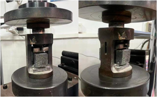
FIGURE 2. Depiction of the compressive strength test of the UHPC-based grouting material.
The expansion degree of the UHPC-based grouting material was used to represent its flow performance, while the test is shown in Figure 3.
3 Material test results
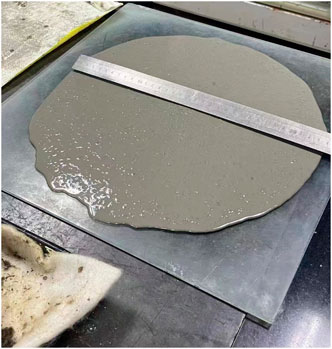
FIGURE 3. Depiction of the expansion degree test of the UHPC-based grouting material.
The test results of the flexural strength, compressive strength and fluidity of GA and GB grouting material are shown in Table 8.

TABLE 8. Material test results.
The flexural and compressive strengths of GA grouting material are 9.4 MPa and 119.6 MPa, respectively. After adding steel fiber, the flexural strength is increased by about 87%, while the compressive strength is increased by 7%. The incorporation of the steel fiber greatly improves the flexural strength and the compressive strength of the UHPC-based grouting material.
We have to underline that the initial fluidity and 30 min retention value of the GA grouting material meet the specification requirements. The initial fluidity of the GB grouting material is low, but its 30 min fluidity meets the specification requirements. After steel fiber is incorporated, the initial fluidity and 30 min retention value of the UHPC-based grouting material are decreased by 8.1 % and 5.7%, respectively. The incorporation of the steel fiber limits also the free flow of slurry, reduces the flow performance of the UHPC-based grouting material and increases the grouting difficulty.
3 General Situation of Connection Performance Test
3.1 Specimen Design
The diameter of the sleeve steel bars that are used in industrial and civil buildings is generally lower than 25 mm. Meanwhile, large-scale infrastructures such as bridges, mostly use large-diameter steel bars above 25 mm. With the increase of the steel bar diameter, the thickness of the protective layer and sleeve size should also be appropriately increased to meet the anchorage requirements of the steel bar. By changing the steel bar anchorage length la and the mixing proportion of the UHPC-based grouting material, eight specimens of steel bar connection joints were made, and monotonic axial tension tests were carried out on eight specimens. The construction of the specimen is revealed in Figure 4, and the detailed dimensions are shown in Table 9. The meaning of each letter and number with the specimen ‘S400-GA-8d’ is the following: ‘S’ denotes the specimen, ‘400’ stands for the grade of steel bar HRB400, ‘GA’ represents the grouting material without steel fiber UHPC, and ‘8d’ denotes the anchorage length that is eight times the diameter of the steel bar.
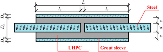
FIGURE 4. Diagram of the specimen construction.
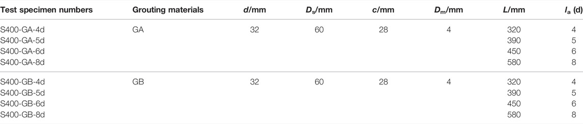
TABLE 9. Depiction of the specimen sizes.
3.2 Material Properties
The grouting sleeves adopt the JM fully grouted sleeve, as is shown in Figure 5. The JM fully grouted sleeve is rolled with high-quality carbon structural steel. The outer wall of the sleeve was pressed into the internal 4 mm, and the trapezoidal convex rib with a pitch of 40 mm was formed on the inner wall to increase the bonding area between the sleeve and the grouting material, as well as to improve the interface bonding strength.
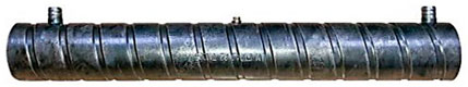
FIGURE 5. Depiction of the JM fully grouted sleeve.
The HRB400E steel bar with a diameter of 32 mm was selected for the material performance test, whereas a universal testing machine carried out the uniaxial tensile test. The measured mechanical properties of the HRB400E steel bar are shown in Table 10.

TABLE 10. Properties of the steel reinforcement materials.
3.3 Fabrication of Specimens
Before assembling the specimens, the paste position of the strain gauge should be smoothly polished in advance. Then, the relative position between the sleeve and the steel bar, as required in Table 9, and insert the rubber plug after assembly to prepare the grouting. During the grouting, put the well-configured grouting material into the grouting gun for artificial pressure grouting. During the grouting process was fixed. Interestingly, it was found that the fluidity of GB grouting material was low, and the grouting was difficult. On the other hand, the fluidity of the GA grouting material was good, and the grouting was easy. However, the GB grouting material was still used to continue pouring four groups of specimens and exploring the influence of the steel fiber on the interfacial bonding strength. After grouting, the specimen was placed in the standard curing room for 28 days, and the strain gauge was pasted at the measuring point after curing.
3.4 Measuring Point Arrangement and Loading Device
The applied test measurement includes displacement and load between fixtures, residual deformation, the surface strain of sleeves, and the steel bar strain. The uniaxial tensile tests were carried out on a 2000 kN electro-hydraulic servo universal testing machine. The displacement and load between fixtures and the residual deformation of the specimen during the test are automatically recorded by the machine. The overall displacement measured by the device includes the slippage between the rebar and loading head in the initial loading stage. The sleeve’s surface strain and the steel bar’s strain are read after connecting the data acquisition box with the pre-pasted strain gauge. By considering the symmetry of the sleeve, the strain gauges are pasted only at the loading end of the sleeve and the steel bar. The position of the strain gauge is shown in Figure 6.
FIGURE 6. Layout of the strain gauge.
3.5 Loading Rate and Loading Protocol
Before the loading process, the clamp will exert a horizontal extrusion force on the joint, which should be kept constant throughout the test to ensure that the joint does not slip during axial tension. At the same time, the horizontal thread between fixtures can prevent the specimen from axial sliding. The loading rate of the uniaxial tensile test was 2 MPa/s. As far as the specimen loading system is concerned, in accordance with the provisions of the Technical specification for mechanical splicing of steel reinforcing bars (JGJ107-2016), it was firstly loaded at 0.6 times the steel yield strength standard value. Then, it was unloaded to 0 to measure the residual deformation of the specimen. According to the loading rate of 2 MPa/s, the specimen was loaded to failure.
4 Test Results and Analysis
4.1 Failure Mode of Specimen
The specimen has two failure modes during the uniaxial tensile test: slip failure and tensile failure. The failure mode of the specimen is shown in Figure 7.
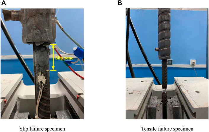
FIGURE 7. Failure mode of specimens (A) Slip failure specimen (B) Tensile failure specimen. capacity of the specimen with the anchorage length of 8 d is greater than the standard value of the tensile strength of the steel bar, the grade I joint standard is met. The value of specimens
During the test, all specimens were damaged after experiencing the elastic-yield-strengthening stage. More specifically, S400-GA-8d and S400-GB-8d exhibited tensile failures, whereas the other specimens showed slip failures. When the load reached the ultimate tensile strength, the phenomenon of the steel bar necking occurs, and its diameter decreased significantly. As the load continues to increase, the lower end of the connecting steel bar was broken and a violent noise was recorded. For the specimen with the slip failure, when the load reached a certain degree, the steel-grouting material interface of UHPC at the end of the sleeve was gradually peeled off and separated. The connecting steel bars produced also an obvious sliding effect. With the continuous increase of the enforced load, the slip area of the steel bar was significantly expanded, the steel bar in the anchorage zone was exposed, and some UHPC-based grouting materials were observed on the surface.
On top of that, the grouting material splits with the increasing load. The crack is developed continuously, and the binding effect of end concrete is weak. The splitting cracks are developed rapidly, resulting in a partial failure of the end grouting material. The failure of the grouting material or excessive deformation of reinforcement will lead to a local slip of the specimen, and the chemical bonding force between reinforcement and grouting material in the slip zone is disappeared. At this time, the bonding force between the steel bar and the grouting material is mainly composed of two parts: 1) the friction between the grouting material and the steel bar and 2) the mechanical bite force between the grouting material and the steel bar transverse ribs. When the load continued to increase, the process can be approximately regarded as a quasi-static process. If the ultimate bearing capacity of the steel bar was higher than the bonding force of the grouting material, the specimen will slip to failure. Conversely, the tensile failure of the specimen occurs.
4.2 Load Displacement Curve
The 2000 kN electro-hydraulic servo universal testing machine was used to conduct a monotonic axial tensile test on eight specimens, while the load-displacement curve is shown in Figure 8, The displacement in the figure includes the slippage between the rebar and the loading head at the initial stage of loading. As can be observed from Figure 8:
1) The specimen of the HRB400E grade steel bar connection joint experienced three stages from initial loading to failure, namely elastic stage, yield stage and strengthening stage. However, the load-displacement curve of the specimen was different due to the different anchorage lengths.
2) The failure load of both S400-GA-4d and S400-GB-4d specimens was significantly lower than that of other specimens. The spalling degree of the grouting material was lighter when the specimen was destroyed, and a small amount of grouting material was attached to the surface of the steel bar after the specimen was pulled out. Additionally, the failure load of both S400-GA-5d and S400-GB-5d was slightly higher than the specimen with the same grouting material anchorage length of 4d, and the spalling of grouting material also occurred when the specimen was destroyed. As far as the failure load of both S400-GA-6d and S400-GB-6d specimens is concerned, it was close to the tensile strength of steel bars, whereas still a certain residual strength after failure was measured. The tensile failure occurred in both S400-GA-8d and S400-GB-8d steel bars. When the steel bar was broken, the load decreased rapidly after reaching the ultimate tensile strength of the steel bar. The steel bar firstly appeared during the necking phenomenon. The lower end of the steel bar was broken with severe noise, and the spalling degree of grouting material was high.
3) When the same anchorage length was enforced, the failure load of the GA grouting material specimen was lower than that of the GB grouting material specimen. This effect indicates that the incorporation of steel fiber in the grouting material can improve the tensile bearing capacity of the specimen.
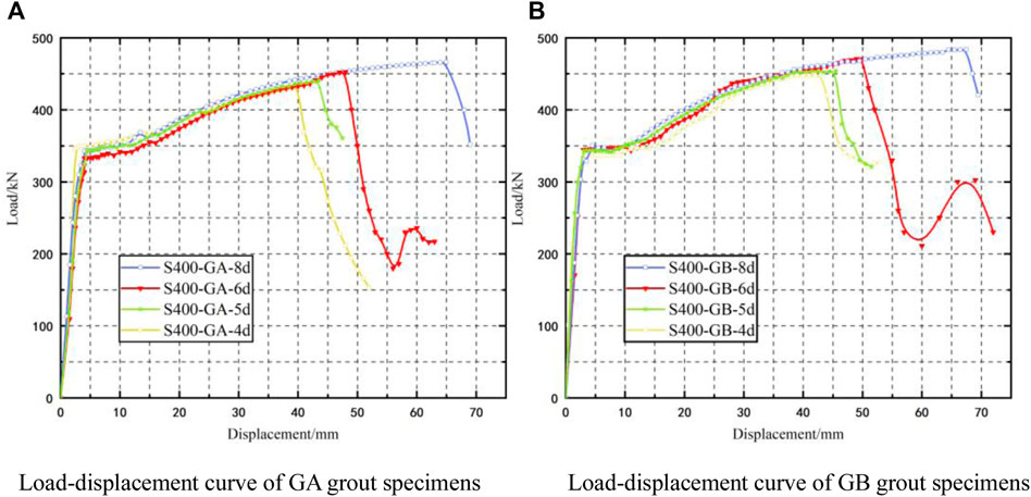
FIGURE 8. Distribution of the load displacement curve (A)Load-displacement curve of GA grout specimens(B)Load-displacement curve of GB grout specimens.
4.3 Stress Analysis of Steel bar Connection Joint
The Technical specification for mechanical splicing of steel reinforcing bars (JGJ 107–2016) is provided for Class I joints under uniaxial tension as follows: for the tensile fracture specimen of the steel bar, its ultimate bearing capacity should be greater than the tensile strength of reinforcement. For the specimen with connector damage (sleeve fracture, sleeve longitudinal cracking, and reinforcement pulling out), the ultimate bearing capacity shall be greater than 1.10 times the tensile strength of reinforcement. Moreover, when the diameter of the steel bar is less than or equal to 32 mm, the residual deformation of the specimen should be less than or equal to 0.1. Table 11 shows that the residual deformation of each specimen is less than 0.1, and the ultimate bearing.
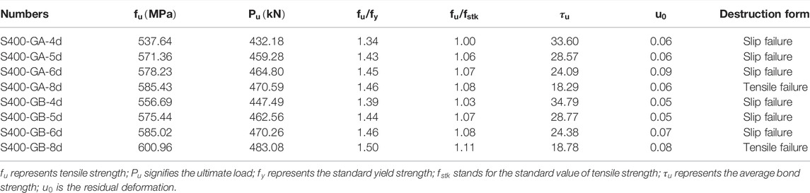
TABLE 11. Test results.
The value
4.4 Analysis of Bond Strength of Specimens
4.4.1 Bond-Slip Bearing Capacity
The specimens with bond-slip failure experienced elastic and yield stages and then were destroyed in the strengthening stage. As a result, the bearing capacity decreased sharply. Among them, the S400-GB-6d and S400-GA-6d specimens still maintained a certain residual bond strength. For the specimens with slip failure, the average bond stren, gth and residual bond strength could be determined according to Formulas 1, 2:
where
The average bond strength of each specimen is listed in Table 11. When the bond strength of the specimen is greater than the tensile strength of the steel bar, the tensile failure of the specimen occurs. Therefore, the actual average bond strength of tensile specimens should be higher than the calculated value of Formula (1). In Figure 8, the load of the specimens S400-GB-6d and S400-GA-6d decreased sharply after the sliding failure. When the load was decreased to the value of 182 kN and 211 kN, respectively, the load increased again. The bond strength of both S400-GB-6d and S400-GA-6d specimens’ residual bond that was calculated by Formula (2) was about 40 % and 45% of that before failure, indicating that the specimens with slip failure retain a certain strength.
4.4.2 Impact of Anchorage Length on Bond Strength
The bond strength of the six slip failure specimens in the uniaxial tensile test is shown in Figure 9. In the figure, the transverse coordinate is the reciprocal of the anchorage length multiple of the steel bar, and the ordinate is the ratio of the average bond strength to
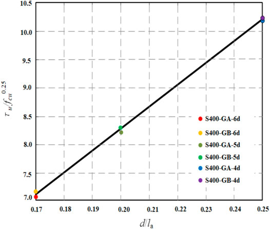
FIGURE 9. Fitting curves of calculated bond strength of specimens with different anchorage lengths.
The bond strength at the interface between the reinforcement and grouting material was unevenly distributed. The bite bond is formed between the transverse rib of the steel bar and the grouting material gradually fails, leading to the creation of a new slip surface. The slip plane is expanded internally, resulting in the pullout of the steel bar and the grouting material between the ribs. Therefore, the decrease in anchorage length reduces the number of the interlocking keys, and the average bond strength is closer to the ultimate bond strength under slip failure. Conversely, the employment of a relatively long anchorage length leads to greater differences between the average bond strength and the ultimate bond strength.
4.4.3 Impact of Grouting Material Types on Bond Stress
Figure 9 displays that the bond strength of the GB grouting material containing steel fiber is slightly higher than that of GA at the same anchorage length. The origins of this effect are associated with the fact that the bond stress of the grouting material is greatly affected by the splitting strength of the grouting material. The steel fiber in the GB grouting material can significantly improve its splitting strength and initial crack strength. Besides, the generation and development of initial cracks are limited to improve the interface bonding strength and the anchorage length of the steel bars is reduced. At the same time, when the slip failure occurs in the test, the existence of the steel fiber can improve the residual bond strength of the failure specimen. Figure 9 shows that the bearing capacity of both S400-GB-6d and S400-GA-6d are basically the same. However, after the steel fiber is added, the residual bearing capacity is increased by about 16%, indicating that the steel fiber of the damaged specimen still maintained a certain working performance.
4.4.4 Sleeve and Steel bar Strain
Strain gauges were pasted on the surface of the sleeve and steel bar to observe the strain change of the specimen during loading. The layout of the applied strain gauges is shown in Figure 6. The strains of both S400-GB-8d and S400-GA-6d before yielding were obtained, as is shown in Figure 10.
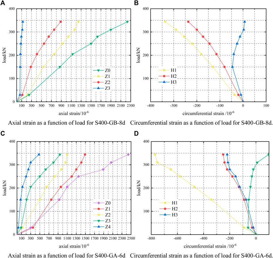
FIGURE 10. Distribution of the strain-load curve of the sleeve (A) Axial strain as a function of load for S400-GB-8d. (B) Circumferential strain as a function of load for S400-GB-8d. (C) Axial strain as a function of load for S400-GA-6d. (D) Circumferential strain as a function of load for S400-GA-6d.
As can be ascertained from Figures 10A,C, the strain of the steel bars is tensile and is increased linearly with the applied load. The sleeve strain is also increased linearly before the specimen yield, showing a distribution law of large in the middle and small parts of both ends. Under enforcing the same load, the absolute value of the axial strain and circumferential strain on the sleeve surface is decreased from the middle to both ends of the sleeve. That is, the greater the strain range is recorded closer to the middle section of the sleeve. The micro-strain value at Z0 varies from 0 to 1500, while the micro-strain value between Z0 and the sleeve end varies from 0 to 1,100. Meanwhile, the strain value at the sleeve end is always small. When the load is increased to 300 kN, the end hoop strain H4 and H3 of the S400-GB-8d and S400-GA-6d exhibit a transition from a compressive strain to a tensile strain.
The data measured by the hoop strain gauge of the sleeve mainly consists of two parts. The first part is the tensile strain of the sleeve caused by the compression expansion of the internal grouting material and stems from the shear of the transverse rib of the steel bar. The implementation of a large load leads to a stronger shear effect, and the tensile strain is increased accordingly. The second part is the compressive strain of sleeves affected by the Poisson’s effect. The grouting material can fully transfer the tensile force of the steel bar to the sleeve due to the small splitting degree of the grouting material in the middle, and the two jointly bear the force. At this time, the sleeve strain can be characterized by Poisson’s effect, leading to a compressive strain. Due to the splitting cracks at the end of the grouting material, the force transmission performance is weakened. Therefore, the steel bar transmission process is blocked, and the end of the sleeve tensile stress is decreased. In addition, the Poisson’s effect is weakened. At this time, the tensile strain of the grouting material extrusion cylinder wall is slightly larger than the compressive strain, and the overall performance is the tensile strain.
With the further increase of the anchorage length, the tensile load transferred from the sleeve section is increased gradually. Thus, the micro strain value of the 8d specimen at the same position is slightly higher than that of the 6d specimen. During the test, the sleeve was always in the elastic stage, indicating that the specimen meets the requirements and the safety reserve is high.
5 Conclusions
A UHPC-based grouting material that meets the requirements of rebar connection performance was prepared, and the mix proportion of high-performance grouting material was determined. By performing a material performance test of two UHPC-based grouting materials with different mixing ratios and based on the uniaxial tensile test of eight connection specimens of grouting sleeve reinforced by UHPC-based grouting materials, the following conclusions were obtained:
1) The UHPC-based grouting material, which only contains micro and fine particle components, has high strength, durability, and good working performance. As a result, is suitable for the grouting material connected to the steel sleeve. Furthermore, its bond strength with the steel interface is high.
2) The addition of steel fiber can improve the compressive strength and flexural strength of the UHPC-based grouting material. However, the fluidity of UHPC-based grouting material is reduced, leading to grouting difficulties in the actual construction process. In practical applications, the UHPC-based grouting material without steel fiber is recommended.
3) By increasing the anchorage length of the connecting steel bar, the bearing capacity can be improved. Hence, ultimate bond strength and change in the failure mode of the specimens is attained. The increase in the anchorage length increased the bond area between the steel bar and grouting material. When the same grouting material was used, the implementation of a longer anchorage length led to a lower average bond strength of the specimen.
4) Before the steel bar yield, the strain of the sleeve and the steel bar changed linearly with the increase of the load, whereas the strain of the sleeve surface was decreased from the middle to both ends. During the test, the maximum micro-strain at each position of the sleeve was always less than 1500, which is located in the elastic stage. Hence, it is indicated that the specimen meets the strength requirements and has a high safety reserve.
Data Availability Statement
The original contributions presented in the study are included in the article/Supplementary Material, further inquiries can be directed to the corresponding author.
Author Contributions
TF: investigation, funding acquisition. JH: writing—original draft, date curation, formal analysis. ZZ: writing—review and editing, resources. LM: date curation; ZS: date curation; KW: validation, software; XR: validation.
Funding
This research has been supported by National Natural Science Funds, Grant No. 51408339, China. Natural Science Funds of Shandong Province, Grant No. ZR2021ME227. Postgraduate Education Quality Improvement Program Funds of Shandong Province, Grant No. SDYAL19110.
Conflict of Interest
Authors LM and ZS were employed by China State Construction Engineering Group Co., Ltd, Beijing, China.
The remaining authors declare that the research was conducted in the absence of any commercial or financial relationships that could be construed as a potential conflict of interest
Publisher’s Note
All claims expressed in this article are solely those of the authors and do not necessarily represent those of their affiliated organizations, or those of the publisher, the editors and the reviewers. Any product that may be evaluated in this article, or claim that may be made by its manufacturer, is not guaranteed or endorsed by the publisher.
References
Anagnostopoulos, C. A. (2014). Effect of Different Superplasticisers on the Physical and Mechanical Properties of Cement Grouts. Constr. Build. Mater. 50 (Jan.), 162–168. doi:10.14359/5168422410.1016/j.conbuildmat.2013.09.050
Fan, L., Meng, W., Teng, L., and Khayat, K. H. (2020). Effects of Lightweight Sand and Steel Fiber Contents on the Corrosion Performance of Steel Rebar Embedded in UHPC. Constr. Build. Mater. 238 (30), 117709. doi:10.1016/j.conbuildmat.2019.117709
Fang, S. (2018). Experimental Study on the Behavior of Steel Sleeve Splicing Grouted by RPC. Master dissertation. Changsha: Hunan University.
Haber, Z. B., Saiidi, M. S., and Sanders, D. H. (2015). Behavior and Simplified Modeling of Mechanical Reinforcing Bar Splices. ACI Struct. J. 112 (2), 179. doi:10.14359/51687455
Hayashi, Y., Shimizu, R., Nakatsuka, T., and Suzuki, K. (1993). Bond Stress-Slip Characteristic of Reinforcing Bar in Grout-Filled Coupling Steel Sleeve. Proc. Jpn. Concr. Inst. 15 (2), 256–270. doi:10.1007/s12205-013-1240-x
Hayashi, Y., Shimizu, R., Nakatsuka, T., and Suzuki, K. (1994). Mechanical Characteristics of Grout-Filled Coupling Sleeves of Electric Resistance Welded Steel Tube under Uniaxial Tensile Loads. Concr. Res. Technol. 5, 65–75. doi:10.3151/crt1990.5.2_65
He, S., Mosallam, A. S., Fang, Z., Zou, C., Feng, W., and Su, J. (2018). Experimental Study on CFSC Encased Shear Connectors in Steel-Concrete Composite Joints with UHPC Grout. Constr. Build. Mater. 173, 638–649. doi:10.1016/j.conbuildmat.2018.04.086
Li, Y. (2019). Design and Study on Connection Properties of a New Type of Grouting Sleeve Based on High-Performance Grouting Material. Doctoral dissertation. Wuhan: Wuhan University of Technology.
Ling, J. H., Abd. Rahman, A. B., Ibrahim, I. S., and Abdul Hamid, Z. (2012). Behaviour of Grouted Pipe Splice under Incremental Tensile Load. Constr. Build. Mater. 33, 90–98. doi:10.1016/j.conbuildmat.2012.02.001
Ling, J. H., Abd. Rahman, A. B., and Ibrahim, I. S. (2014). Feasibility Study of Grouted Splice Connector under Tensile Load. Constr. Build. Mater. 50, 530–539. doi:10.1016/j.conbuildmat.2013.10.010
Lu, Z., Huang, J., Li, Y., Dai, S., Peng, Z., Liu, X., et al. (2019). Mechanical Behaviour of Grouted Sleeve Splice under Uniaxial Tensile Loading. Eng. Struct. 186, 421–435. doi:10.1016/j.engstruct.2019.02.033
Moosavi, M., Jafari, A., and Khosravi, A. (2005). Bond of Cement Grouted Reinforcing Bars under Constant Radial Pressure. Cem. Concr. Compos. 27 (1), 103–109. doi:10.1016/j.cemconcomp.2003.12.002
Shao, X., Liu, Y., Qiu, M., and Deng, F. (2020). Research on Performance of Large Diameter Grout-Filled Splice Sleeve Joints with UHPC. China Civ. Eng. J. 53 (2), 11. doi:10.15951/j.tmgcxb.2020.02.007
Sun, X., Wu, T., Wang, L., and Li, H. (2015). Experimental Research on Iron Tailings Sand as Cement-Based Grouting Materials. China Concr. Cem. Prod. (05), 58–61. doi:10.19761/j.1000-4637.2015.05.015
Wu, T., Liu, Q. W., Cheng, R., and Liu, X. (2017). Experimental Study and Stress Analysis of Mechanical Performance of Grouted Sleeve Splice. Eng. Mech. 34 (10), 68–75. doi:10.6052/j.issn.1000-4750.2016.05.0357
Xu, Z., Zhang, Z., and Xu, T. (2021). State-of-the-art Review of Prefabricated Concrete Bridge Structures in 2020. J. Civ. Environ. Eng. (S1), 235–246. doi:10.11835/j.issn.2096-6717.2021.232
Yu, Q., Wang, Z., Bai, S., Fan, B., Zhang, Z., Dong, J., et al. (2021). Tensile Test and Stress Mechanism Analysis of Grouted Sleeve Lapping Connectors for Rebars. J. Harbin Inst. Technol. 53 (04), 96–110. doi:10.11918/202006123
Yu, Q., Xu, X., Yuan, W., Xu, Z., and Lu, X. (2017). Experimental Study of Mechanical Properties of Grouted Sleeve Lapping Connector with Different Lap Lengths under Tensile Load. J. Hunan Univ. Sci. 44 (09), 82–91. doi:10.16339/j.cnki.hdxbzkb.2017.09.010
Keywords: UHPC, Grouting material, sleeve, steel fiber, Mix proportion, Anchorage length
Citation: Fu T, Hou J, Zhu Z, Meng L, Sun Z, Wang K and Ren X (2022) Experimental Study on UHPC-Based Grouting Materials and Mechanical Performance of Grouted Splice Sleeve Joints. Front. Mater. 9:912509. doi: 10.3389/fmats.2022.912509
Received: 04 April 2022; Accepted: 26 May 2022;
Published: 23 June 2022.
Edited by:
Arcady Dyskin, University of Western Australia, AustraliaReviewed by:
Jun Ren, Yunnan University, ChinaZhifang Dong, Xi’an University of Architecture and Technology, China
Copyright © 2022 Fu, Hou, Zhu, Meng, Sun, Wang and Ren. This is an open-access article distributed under the terms of the Creative Commons Attribution License (CC BY). The use, distribution or reproduction in other forums is permitted, provided the original author(s) and the copyright owner(s) are credited and that the original publication in this journal is cited, in accordance with accepted academic practice. No use, distribution or reproduction is permitted which does not comply with these terms.
*Correspondence: Tao Fu, greenvillage_17@163.com