 Limei Hao1
 Zhi Chen
 Weiren Zhu
94% of researchers rate our articles as excellent or good
Learn more about the work of our research integrity team to safeguard the quality of each article we publish.
Find out more
ORIGINAL RESEARCH article
Front. Mater., 19 May 2022
Sec. Metamaterials
Volume 9 - 2022 | https://doi.org/10.3389/fmats.2022.909671
This article is part of the Research TopicMultifunctional and Reconfigurable Electromagnetic and Acoustic MetasurfacesView all 9 articles
We presented tri-band negative modulus acoustic metamaterials (AM), whose operation characteristics could be flexibly designed by changing the three hole sizes (i.e., a1, a2, and a3) of the tri-layer nested split hollow spheres (NSHSs). We demonstrate numerically that tri-band negative modulus can be obtained and each resonant frequency corresponds to the hole size of each split hollow sphere. However, for the case when a1> a2> a3, the negative modulus band in the high frequency region vanishes. An effective sound-force analogue model with coupling interaction is further developed for the accurate prediction of the three resonant frequencies based on equating the tri-layer NSHSs to three spring oscillators in series. As a result of the analytical formulas, three resonant frequencies could be precisely controlled, and a nested AM with a tri-band negative modulus can be flexibly constructed. The proposed AM could be easily extended to multiple operation bands and can be further coupled with negative mass density structures for constructing multi-band double-negative AMs.
Metamaterials is an artificial material composed of subwavelength microstructure, and it exhibits some unique properties, only with difficulty found in natural materials, including negative dielectric constant and negative permeability in the electromagnetic metamaterials (EMMs) (Pendry et al., 1996; Pendry et al., 1999), negative effective modulus, and negative effective mass in the acoustic metamaterials (AMs) (Liu et al., 2000; Fang et al., 2006). Furthermore, metasurfaces has a thickness much smaller than the working wavelength, and it has been rapidly developed in recent years. Based on the negative property, the metamaterials and metasurfaces can be used in state-of-the-art application prospects in gain enhancement (Cheng et al., 2021), bandwidth improvement (Borazjani et al., 2020; Hu et al., 2020), reconfiguring radiation patterns (Janapala et al., 2019), electromagnetic filtering (Wu et al., 2018; Xinjing et al., 2020), transmit array (He et al., 2019), phase correction (Tang et al., 2020), metaholograms (Yoon et al., 2021), absorption (Liu et al., 2019; Guo et al., 2022), deep-sub wavelength imaging (Boccaccio et al., 2021), and so on. On the other hand, according to the response of natural materials to electromagnetic waves, the materials of EMM were usually selected as three types: all-metal, all-dielectric, and hybrid (Al- Alem and Kishk, 2019; Wang et al., 2021; Zhu et al., 2021), whereas that of AM were mainly selected as common engineering materials such as metal, resin, or polymer because these materials have no response to sound waves. In the last two decades, acoustic metamaterials (AMs) have attracted extensive attention.
Liu et al. (2000) presented the first artificial acoustic local resonance-type metamaterials, which can reach negative effective mass densities at a fixed frequency of 400 Hz. In 2006, Fang et al. (2006) demonstrated acoustic metamaterials with a Helmholtz local resonator array, achieving a negative effective modulus in the ultrasonic frequency range. Based on the Helmholtz resonator, AMs with a balloon-shaped soft resonator were proposed, and it can attain a negative effective modulus (Jing et al., 2015). Ding et al. (2010) designed two-dimensional AMs with split hollow spheres that achieved a negative modulus near the resonant frequency. Metamaterials provide a promising way of controlling low-frequency noise. However, it was disadvantageous for local resonance-type AMs that different units have different response frequencies, and that limits its applications. Therefore, based on local resonance, preparing multi-band or broadband AMs with negative modulus has become an urgent requirement.
To achieve multi-band or broadband, many research groups had carried out the research. Ding and Zhao (2011) prepared AMs with multi-band negative modulus, which was composed of seven split hollow spheres with gradual size independently arrayed in a sponge matrix. Zhu et al. (2012) presented a multi-resonant AMs slab for the multiple wave band gaps. The frequency band of tubular AMs was enlarged by adjusting the number of holes in the one-dimensional waveguide (Fan et al., 2012). Luo et al. (2021) developed a waterborne acoustic metamaterial composed of multi-Helmholtz resonators, and it could absorb sound perfectly at low frequencies. AMs with the more similar units can obtain multi-band or broadband.
Furthermore, AMs can reach broadband by combining numerous heterogeneous units. Zhang et al. (2017) proposed a triangular-structure AM in which the negative modulus was widened by controlling the parameters. By combining double-hole hollow sphere arrays with non-uniform double-hole hollow spheres structure, Choi and Yoon (2018) fabricated broadband negative modulus AMs. Xu et al. (2021) proposed a new AM consisting of a resonator and multiple channels, and it could obtain absorption in three frequency bands below 900 Hz. Zhang et al. (2018) investigated aluminum membrane AMs with multi-modal resonant piezoelectric resonators, and the proposed metamaterial could broaden the local resonance bandgaps. An effective bulk modulus can be obtained in a wide frequency range by using the feedback of a piezoelectric diaphragm in the metamaterials composed of a symmetrical double Helmholtz resonator and a main acoustic cavity (Ning et al., 2022). Wang et al. (2017) designed an elastic metamaterial with active multi-resonance piezoelectric shunting that could achieve large attenuation in three frequency bands.
In short, multi-band or broadband can be achieved by assembling numerous similar or heterogeneous structures, and then the size of AMs became heavy and complicated. Our research group (Hao et al., 2018; Hao et al., 2019) had proposed a nested structural unit that can significantly minimize AMs units. The simulated results proved that the number of these resonant frequencies was dependent on the number of layers in the nested multilayer unit (Hao et al., 2018). Chen and Ding (2019) studied the transmission properties of multi-band AMs with the nested multi-layer split hollow spheres from the simulation and experiment. It was found that two-band negative modulus AMs with the nested two-layer split hollow spheres was constructed, but it was not easy for AMs with the tri-layer nested split hollow spheres (NSHSs) to achieve tri-band negative modulus. On the other hand, because the local resonant frequency band is restricted, it becomes important to predict the resonant frequency of the AMs unit precisely. However, the relation between the structural parameters of a nested unit and the resonant frequency was rarely investigated. The effect of the parameters of two-layer split hollow spheres on the transmission properties was investigated in terms of theory and simulation, and then two-band negative modulus could be easily realized by AMs with the nested two-layer split hollow spheres (Hao et al., 2019). Furthermore, the theoretical frequency is in good agreement with the simulation frequency. Thus, it becomes important to check the condition of these nested AMs for tri-band negative modulus and then accurately predict three resonant frequencies.
Based on references (Hao et al., 2018; Chen and Ding, 2019; Hao et al., 2019), the effects of the relative hole diameters of the tri-layer NSHSs on the resonant frequency and effective modulus under four different conditions according to the relative size of three-hole diameters were investigated in terms of sound-force analogy (SFA) and simulation in detail.
Based on previous work (Hao et al., 2019), tri-layer NSHSs are nested by three SHSs of various sizes, and its structural representation is plotted in Figure 1A. R1, R2, and a1 denote the interior radius, exterior radius, and the hole diameter of the first interior layer hollow sphere, respectively. R3, R4, and a2 denote the interior radius, exterior radius, and the hole diameter of the middle second layer hollow sphere, respectively. R5, R6, and a3 denote that of the exterior third layer hollow sphere, respectively. The sound wave enters tri-layer NSHSs from the hole of the third layer sphere, and then passes through the third layer, the hole of the second layer, the second layer, and the hole of the first layer, respectively, and finally gets into the first layer cavity. Thus, based on SFA theory, the cavity and the interlayer are equivalent to springs (k1, k2, and k3), these small holes are equivalent to masses (m1, m2, and m3), and then the tri-layer NSHSs is equivalent to three spring oscillators in series, as illustrated in Figure 1B. According to Newton’s second law of m1, m2, and m3, Eqs. 1–3 are given as follows:
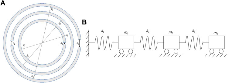
FIGURE 1. (A) Cross-section of tri-layer nested split hollow spheres (NSHSs) and (B) structural scheme of three spring oscillators in series.
where,
the elastic coefficient is as follows:
The effective sound mass is as follows:
The cross-sectional area of the small hole is as follows:
The volume of the spherical cavity is as follows:
The modified effective length of the small hole is as follows:
The mass density and sound speed are denoted by
Let
Let
Then solving Eq. 4, we can get three real roots expression of the frequency, and the resonant frequency of the tri-layer split hollow sphere
Tri-layer NSHS was designed and simulated using COMSOL Multiphysics software based on the finite element method (FEM), and the Pressure Acoustic and Thermal Acoustic Modules were selected to study an acoustic characteristics under the condition of the thermo-viscous losses in the frequency domain. The tri-layer NSHS was put at the center of the waveguide tube. We set its left facet as a radiation boundary with 1Pa planar acoustic wave, its right facet as the matching boundary, and the rest as the hard boundary. The sound was perpendicularly incident into the exterior hole of the tri-layer NSHSs. Considering the viscous loss, the air is set as viscous flow. Furthermore, air medium was set in the waveguide tube and cavity of tri-layer NSHSs, and its density, sound speed, and attenuation coefficient were 1.29 kg/m3, 320 m/s, and 0.01 m−1, respectively.
Tri-layer NSHSs were set as polylactic acid, and the density, Young’s modulus, and Poisson’s ratio were 1000 kg/m3, 3*109 Pa, and 0.37, respectively. The whole simulation domain was meshed by the tetrahedron. The maximum element size was
The values of
To study the influence of the relative diameter of three holes on the transmission and effective modulus, tri-layer NSHSs with three various hole diameters were divided into two groups based on the relative diameters of three holes: gradient type and mutant type. Among them, the gradual type includes the gradually decreasing or increasing diameters of three-holes, that is, a1> a2> a3 and a1< a2< a3, while the mutation type includes the smallest or largest diameters of the middle hole, that is, a2< a1< a3 and a1< a3< a2.
When the three holes’ diameters continuously reduced, that is, the interior hole diameter a1was kept as 0.8 mm, the middle hole diameter a2 was kept at 0.6 mm, and the diameter of exterior hole a3 changed at the range of 0.2–0.6 mm.
Figure 2A shows the transmission curves of the tri-layer NSHSs with various exterior hole diameters. As seen in Figure 2A, the transmission absorption peaks near three resonant frequencies became shallower as the exterior hole diameter decreased. This is because when the exterior hole diameter gradually decreased, the sound energy that could enter the three-layer hollow sphere system shrank as well. For the tri-layer NSHSs with various exterior hole diameters, the difference in transmission absorption peak values was minor in the low-frequency region, the difference grew greater in the medium frequency region, and the difference in the transmission peak was the biggest in the high-frequency region.
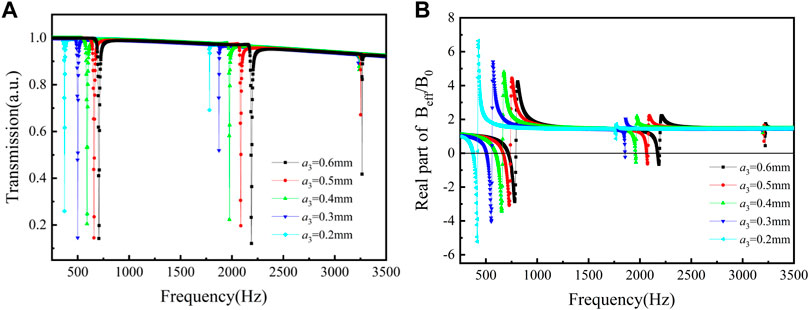
FIGURE 2. Curves of the tri-layer NSHSs with various exterior hole diameters under the condition of a1> a2> a3. (A) Transmission and (B) the real part of effective modulus.
Furthermore, the effective modulus curves of the tri-layer NSHSs with various exterior hole diameters are depicted in Figure 2B. For the low frequency of the deepest transmission peak, the negative moduli could be realized around the resonant frequencies with varying exterior hole diameters. With decreasing exterior hole diameters, the effective modulus in the medium frequency region neared zero. When the exterior hole diameters a3 was 0.2 mm, the effective modulus around the resonant frequency was positive. The reason is that the sound energy was predominantly collected between the second and third layers, and the local resonance appeared around both the second and the third layer holes (see Figure 3). However, when the hole in the third layer was very small, and the resonance was weak, the negative effective modulus was not attained for the medium frequency region. For high frequencies with the shallowest transmission peak, the negative effective modulus could not be achieved. It was thought that the sound energy was predominantly collected between the first and second layers, and the weakest local resonance appeared only around the first and the second layer holes.
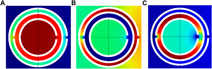
FIGURE 3. Energy distribution of tri-layer NSHSs at the various resonant frequency with a3 = 0.6 mm under the condition of a1> a2> a3. (A) Low frequency, (B) medium frequency, and (C) high frequency.
Figure 4 shows the relationship curves of the exterior hole diameter a3 and the resonant frequency under the condition of a1> a2> a3, where the solid circle, triangle, and diamond signs represent the simulated low-, medium-, and high-resonant frequency, respectively, and the lines are the calculation curves resulting from Eqs. 5–7. Furthermore, it can be seen from Figure 4 that the resonant frequencies calculated by the uncoupled model of the three spring oscillators in series were essentially consistent with the simulated resonant frequencies. Combined with Figure 3, it could also be found that the sound energy at the low-, medium-, and high-resonant frequencies belonged to the corresponding layers, and the corresponding energy was not coupled with each other layer. Due to the smallest exterior hole diameter, this relatively weak or no coupling interaction had little effect on the calculated resonant frequency from the model. However, the hole diameter in each layer had a great effect on the transmission, the transmission at high frequency was shallow, and it was difficult to achieve negative modulus.
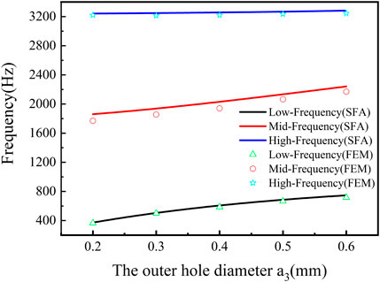
FIGURE 4. Relationship curves of the exterior hole diameter and the resonant frequency under the condition of a1> a2> a3.
When the three holes’ diameters continuously increased, that is, a1< a2< a3, the interior hole diameter a1 was kept as 0.2 mm, the middle hole diameter a2 was kept at 0.4 mm, and the diameter of exterior hole a3 changed at the range of 0.6–1.2 mm.
Figure 5A depicts the transmission of the tri-layer NSHSs with different diameters of exterior hole
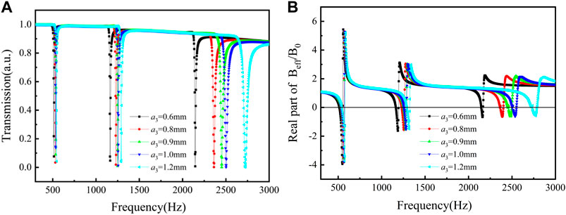
FIGURE 5. Curves of the tri-layer NSHSs with various exterior hole diameters under the condition of a1< a2< a3. (A) Transmission and (B) the real part of effective modulus.
Figure 6 is the relationship curves of the exterior hole diameter and the resonant frequency, where the solid circle, triangle, and diamond signs represent the simulated low-, medium-, and high-resonant frequency, and the line represents calculation curves resulting from Eqs. 5–7. In the low-frequency region, the resonant frequencies of tri-layer NSHSs with varying exterior hole diameters were the same, which agreed well with the simulated resonant frequencies (see Figure 6). At the medium-frequency region, the resonant frequencies had a slight blue shift, but they were consistent with the simulated value. In the high-frequency region, with increasing the exterior hole diameter, the resonant frequency gradually shifted blue. When exterior hole diameters became larger, the weak coupling interaction maybe results in a negative modulus at the high-frequency region. Considering the coupling interaction (Ding et al., 2019), the change rate of acoustic susceptance was proportional to G, and the resonant frequency was modified by the formula
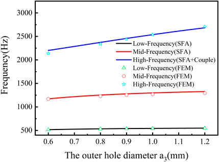
FIGURE 6. Relationship curves of the exterior hole diameter and the resonant frequency under the condition of a1< a2< a3.
When the hole in the middle layer was smallest, that is, a2< a1< a3, the interior hole diameter a1 was kept as 0.6 mm, the middle hole diameter a2 remained at 0.4 mm, and the diameter of exterior hole a3 changed at the range of 0.6–0.9 mm.
Figure 7A depicts the transmission of the tri-layer NSHSs with different diameters of exterior holes under the condition of a2< a1< a3. As illustrated in Figure 7A, the transmission absorption peaks near the low- and medium-frequency were rather deep (all less than 0.1). With increasing the exterior hole diameters, the transmission absorption peaks in the high-frequency region became deeper. This is because when the diameter of exterior hole a3 rose, sound energy that can enter the tri-layer NSHSs increased, and the transmission absorption peak deepened.
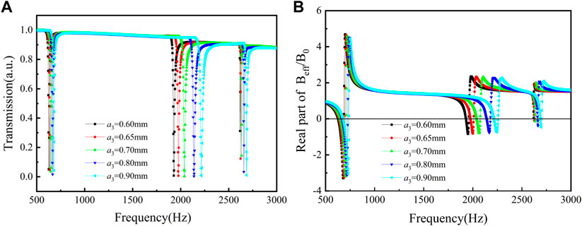
FIGURE 7. Curves of the tri-layer NSHSs with various exterior hole diameters under the condition of a2< a1< a3. (A) Transmission and (B) the real part of effective modulus.
Furthermore, the effective modulus curves of the tri-layer NSHSs with different exterior hole diameters under the condition of a2< a1< a3 is shown in Figure 7B. It is found that the negative moduli could be realized with varying exterior hole diameters around the low- and medium-resonant frequencies. However, when the diameter of the exterior hole a3 was increased, the tri-layer NSHSs finally achieved the negative effective modulus near the high-resonant frequency. Whereas, when a3 was 0.6 mm, the effective modulus around the resonant frequencies was positive. It was the reason that the sound energy was collected predominantly between the first layer and second layers, and the local resonance only appeared around two holes of the first layer and the second layer (see Figure 8). With increasing the exterior hole diameter, for instance, when a3 is 0.9 mm, the sound energy was collected between the first layers, the second layers, and the third layer, and the local resonance appeared three holes, resulting in the weak coupling interaction and then the negative effective modulus, as seen in Figure 8.
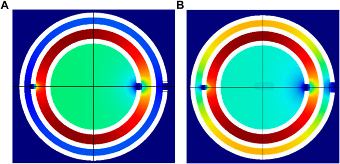
FIGURE 8. Energy distribution of tri-layer NSHSs at the high resonant frequency under the condition of a2< a1< a3. (A)
Figure 9 demonstrates the relationship curves of a3 and the resonant frequency under the condition of a2< a1< a3, where the solid circle, triangle, and diamond signs represent the low-, medium-, and high-resonant frequency from the simulated results, and the line is the calculated curves from Eqs. 5–7. It is found that the resonant frequencies of tri-layer NSHSs with varying exterior hole diameters had a slight blue shift at low- and high-resonant frequencies, and they coincided with the simulated resonant frequencies. It is thought that due to the smallest middle hole diameter, this relatively weak coupling interaction had little effect on the calculated resonant frequency from the model. For the medium-frequency region, the resonant frequencies had a noticeable blue shift, and the little difference between the calculated and simulated resonant frequencies gradually appeared with the increase in the exterior hole diameter.
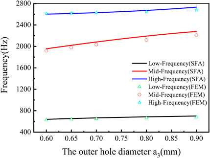
FIGURE 9. Relationship curves of the exterior hole diameter and the resonant frequency under the condition of a2< a1< a3.
When the hole in the middle layer was largest, that is, a1< a3< a2, the interior hole diameter
Figure 10A depicts the transmission of the tri-layer NSHSs with different diameters of exterior hole under the condition of a1< a3< a2. It is found that the transmission absorption peaks near three resonant frequencies were relatively deep (all less than 0.1). The real part of the effective modulus curves of the tri-layer NSHSs with different diameters of exterior holes is demonstrated in Figure 10B. As illustrated from Figure 10B, the effective moduli became negative near the low- and medium-resonant frequencies with varying exterior hole diameters. Furthermore, with decreasing the exterior hole diameters, the transmission absorption peaks around high-resonant frequency got shallower. When a3 was 0.6 mm, the effective modulus around the resonant frequencies was positive (0.09). When, a3 was 0.9 mm, the negative effective modulus (−0.16) could be achieved. Thus, the bigger a3, the easier it was to obtain the negative modulus.
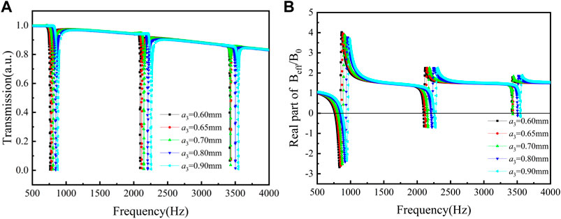
FIGURE 10. Curves of the tri-layer NSHSs with various exterior hole diameters at R5 = 6.44 mm and R6 = 6.94 mm under the condition of a1< a3< a2. (A) Transmission and (B) the real part of effective modulus.
Figure 11 depicts the relationship of a3 and the resonant frequency under the condition of a1< a3 <a2. It was seen that the resonant frequencies of tri-layer NSHSs with various exterior hole diameters at the low-, medium-, and high-resonant frequencies had a slight blue shift, and the low- and medium-resonant frequencies coincided with the simulated resonant frequencies. However, the resonant frequencies in the high-frequency region had a slight blue shift as well. Due to a relatively strong coupling interaction between the layers of the tri-layer NSHSs with varying exterior hole diameters (see Figure 12), similar to section 3.2, the calculated frequency was obtained by the modified coupled series spring oscillators model, and it coincided with the simulated resonant frequency.
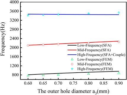
FIGURE 11. Relationship curves of the exterior hole diameter and the resonant frequency of tri-layer NSHSs with R5 = 6.44 mm and R6 = 6.94 mm under the condition of a1< a3< a2.
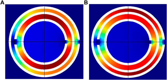
FIGURE 12. Energy distribution of tri-layer NSHSs at the high resonant frequency of tri-layer NSHSs with R5 = 6.44 mm and R6 = 6.94 mm under the condition of a1< a3< a2. (A) a3 = 0.6 mm and (B) a3 = 0.9 mm.
To weaken the effect of the weak coupling interaction on the calculated resonant frequency, the new parameters of R5 = 7.50 mm and R6 = 8.00 mm was set, but the other parameters were left as they were in this section.
As seen in Figures 13A,B, the transmission absorption peaks in the low- and medium-frequency regions were relatively deep, and the effective moduli became negative near the resonant frequency. Whereas, the transmission absorption peaks in the high-frequency region were shallow, and the negative modulus for the tri-layer NSHSs with the big third layer could not be obtained.
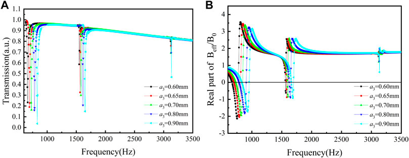
FIGURE 13. Curves of the tri-layer NSHSs with various exterior hole diameters at R5 = 7.50 mm and R6 = 8.00 mm under the condition of a1< a3< a2. (A) Transmission and (B) the real part of effective modulus.
As a result, the resonant frequencies had no blue shift in the high-frequency region, and the difference between the calculated and simulated resonant frequency became almost zero (see Figure 14), which may be due to the very weak coupling interaction caused by expanding the radius of the third layer (see Figure 15). However, it is not beneficial to achieve the negative modulus. Thus, to predict three resonant frequencies of tri-layer NSHSs precisely, the coupling interaction was considered to be incorporated into the theoretical three spring oscillators in series model under the condition of a1< a3< a2.
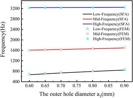
FIGURE 14. Relationship curves of the exterior hole diameter and the resonant frequency of tri-layer NSHSs with R5 = 7.50 mm and R6 = 8.00 mm under the condition of a1< a3< a2.
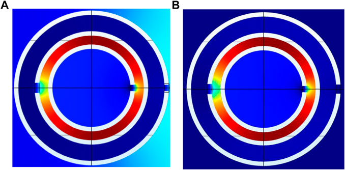
FIGURE 15. Energy distribution of tri-layer NSHSs at the high resonant frequency of tri-layer NSHSs with R5 = 7.50 mm and R6 = 8.00 mm under the condition of a1< a3< a2. (A) a3 = 0.6 mm and (B) a3 = 0.9 mm.
In summary, increasing the exterior hole diameter and the weak coupling interaction made it easier to reach the negative effective modulus under the condition of a1< a2< a3, a2< a1< a3 and a1< a3< a2. In order to predict the resonant frequency in the high frequency region and obtain the negative modulus, this relatively weak coupling interaction must be considered, and the modified coupled model was obtained by combining the coupling interaction with the three spring oscillators in series model, which can predict three resonant frequencies of the nested tri-layer NSHSs.
We present a tri-band negative modulus AMs based on nested tri-layer NSHSs. Three resonant frequencies were accurately deduced from the three spring oscillators in series model. It was indicated that tri-layer NSHSs appeared in three resonant frequencies. Three resonant frequencies underwent a blue shift as the hole diameter increased. The calculated and simulated resonant frequencies were in good agreement under the conditions of three decreasing holes and the smallest middle holes. Whereas, the simulated resonant frequency in the low and medium frequency regions were consistent with the calculated resonant frequency under the conditions of three increasing holes and the largest middle holes; the difference between the calculated and simulated resonant frequencies in the high-frequency region was eliminated by combining the coupling interaction with the model. Thus, the proposed three spring oscillators in series model with coupling interaction can effectively predict, and AMs under all four conditions can easily realize negative modulus near three predicted resonant frequencies. As a result of the analytical formulas, three resonant frequencies may be precisely controlled, and a nested type AM with a tri-band negative modulus can be easily constructed, which will be beneficial for the application of noise control engineering in the expected and accurate frequency band.
The original contributions presented in the study are included in the article/Supplementary Material, further inquiries can be directed to the corresponding authors.
Conceptualization, LH and XY. Data curation, YL, XG, and SP. Formal analysis, YL and XY. Investigation, LH, XY, and ZC. Methodology, XY and YX. Project administration, LH. Software, XG, XY, and SP. Supervision, ZC. Writing—original draft, LH and YL. Writing—review and editing, ZC and WZ.
This work was supported by the National Natural Science Foundation of China (Grant Nos. 11974275 and 11304243), the Natural Science Foundation of Shaanxi Province, China (Grant Nos. 2014JQ1039 and 2019JM-157), and the National College Students’ Innovation and Entrepreneurship Project (Grant No. 202110704029).
The authors declare that the research was conducted in the absence of any commercial or financial relationships that could be construed as a potential conflict of interest.
All claims expressed in this article are solely those of the authors and do not necessarily represent those of their affiliated organizations, or those of the publisher, the editors, and the reviewers. Any product that may be evaluated in this article, or claim that may be made by its manufacturer, is not guaranteed or endorsed by the publisher.
Al-Alem, Y., and Kishk, A. A. (2019). Wideband Millimeter-Wave Dielectric Resonator Antenna with Gain Enhancement. Antennas Wirel. Propag. Lett. 18 (12), 2711–2715. doi:10.1109/LAWP.2019.2949947
Boccaccio, M., Rachiglia, P., Malfense Fierro, G. P., Pio Pucillo, G., and Meo, M. (2021). Deep-Subwavelength-Optimized Holey-Structured Metamaterial Lens for Nonlinear Air-Coupled Ultrasonic Imaging. Sensors 21, 1170. doi:10.3390/s21041170
Borazjani, O., Naser-Moghadasi, M., Rashed-Mohassel, J., and Sadeghzadeh, R. A. (2020). Bandwidth Improvement of Planar Antennas Using a Single-Layer Metamaterial Substrate for X-Band Application. Int. J. Microw. Wireless Technol. 12 (9), 906–914. doi:10.1017/S1759078720000264
Chen, H., and Ding, C. (2019). Simulated and Experimental Research of Multi-Band Acoustic Metamaterial with a Single Resonant Structure. Materials 12, 3469. doi:10.3390/ma12213469
Cheng, H., Hua, L., Wang, Y., Yang, H., and Lu, T. (2021). Design of High Gain Vivaldi Antenna with a Compound Optical Lens Inspired by Metamaterials. Int. J. RF Mic Comp-aid Eng. 31 (4), e22570. doi:10.1002/mmce.22570
Choi, J. S., and Yoon, G. H. (2018). Acoustic Metamaterials with Combined Heterogeneous Double-Split Hollow Sphere for Noise Reduction. J. Vibration Control. 24 (21), 107754631773979–107754631774944. doi:10.1177/1077546317739794
Ding, C.-L., and Zhao, X.-P. (2011). Multi-band and Broadband Acoustic Metamaterial with Resonant Structures. J. Phys. D: Appl. Phys. 44, 215402. doi:10.1088/0022-3727/44/21/215402
Ding, C., Dong, Y., Song, K., Zhai, S., Wang, Y., and Zhao, X. (2019). Mutual Inductance and Coupling Effects in Acoustic Resonant Unit Cells. Materials 12, 1558. doi:10.3390/ma12091558
Ding, C. L., Hao, L. M., and Zhao, X. P. (2010). Two-dimensional Acoustic Metamaterial with Negative Modulus. J. Appl. Phys. 108, 074911. doi:10.1063/1.3493155
Fan, L., Ge, H., Zhang, S.-y., and Zhang, H. (2012). Research on Pass Band with Negative Phase Velocity in Tubular Acoustic Metamaterial. J. Appl. Phys. 112, 053523. doi:10.1063/1.4751270
Fang, N., Xi, D., Xu, J., Ambati, M., Srituravanich, W., Sun, C., et al. (2006). Ultrasonic Metamaterials with Negative Modulus. Nat. Mater 5, 452–456. doi:10.1038/nmat1644
Guo, J., Zhang, X., Fang, Y., and Qu, R. (2022). An Extremely-Thin Acoustic Metasurface for Low-Frequency Sound Attenuation with a Tunable Absorption Bandwidth. Int. J. Mech. Sci. 213, 106872. doi:10.1016/j.ijmecsci.2021.106872
Hao, L., Men, M., Wang, Y., Ji, J., Yan, X., Xie, Y., et al. (2019). Tunable Two-Layer Dual-Band Metamaterial with Negative Modulus. Materials 12, 3229. doi:10.3390/ma12193229
Hao, L., Men, M., Zuo, Y., Yan, X., Zhang, P., and Chen, Z. (2018). Multibands Acoustic Metamaterial with Multilayer Structure. J. Phys. D: Appl. Phys. 51 (38), 385104. doi:10.1088/1361-6463/aad6d7
He, K., Liu, Y. D., and Fu, Y. Q. (2019). Transmit-Array, Metasurface-Based Tunable Polarizer and High-Performance Biosensor in the Visible Regime. Nanomaterials 9 (4), 603. doi:10.3390/nano9040603
Hu, B., Zhang, Z., Yu, D., Liu, J., and Zhu, F. (2020). Broadband Bandgap and Shock Vibration Properties of Acoustic Metamaterial Fluid-Filled Pipes. J. Appl. Phys. 128 (20), 205103. doi:10.1063/5.0030179
Janapala, D. K., Caspe, F. S., and Moses, N. (2019). Metasurface Based Pattern Reconfigurable Antenna for 2.45 GHz ISM Band Applications. Int. J. RF Microw Comput. Aided Eng. 29 (12), e22007. doi:10.1002/mmce.22007
Jing, X., Meng, Y., and Sun, X. (2015). Soft Resonator of Omnidirectional Resonance for Acoustic Metamaterials with a Negative Bulk Modulus. Sci. Rep. 5, 16110. doi:10.1038/srep16110
Liu, C. R., Wu, J. H., Lu, K., Zhao, Z. T., and Huang, Z. (2019). Acoustical Siphon Effect for Reducing the Thickness in Membrane-type Metamaterials with Low-Frequency Broadband Absorption. Appl. Acoust. 148, 1–8. doi:10.1016/j.apacoust.2018.12.008
Liu, Z., Zhang, X., Mao, Y., Zhu, Y. Y., Yang, Z., Chan, C. T., et al. (2000). Locally Resonant Sonic Materials. Science 289, 1734–1736. doi:10.1126/science.289.5485.1734
Luo, Y. Q., Lou, J. J., and Zhang, Y. B. (2021). An Acoustic Absorbing Metamaterial with Multi-Helmholtz Resonators at Low-Frequency Underwater. Mod. Phys. Lett. B 35 (23), 2150397. doi:10.1142/S0217984921503978
Ning, L., Wang, Y.-Z., and Wang, Y.-S. (2022). Concentrating and Black Hole like Structures by Elastic Metamaterials with Acoustic Cavities under Active Feedback Control. Waves in Random and Complex Media 32 (1), 155–173. doi:10.1080/17455030.2020.1767318
Pendry, J. B., Holden, A. J., Robbins, D. J., and Stewart, W. J. (1999). Magnetism from Conductors and Enhanced Nonlinear Phenomena. IEEE Trans. Microwave Theor. Techn. 47, 2075–2084. doi:10.1109/22.798002
Pendry, J. B., Holden, A. J., Stewart, W. J., and Youngs, I. (1996). Extremely Low Frequency Plasmons in Metallic Mesostructures. Phys. Rev. Lett. 76, 4773–4776. doi:10.1103/PhysRevLett.76.4773
Tang, S., Wang, R., Han, J., and Jiang, Y. (2020). Acoustic Energy Transport Characteristics Based on Amplitude and Phase Modulation Using Waveguide Array. J. Appl. Phys. 128 (16), 165103. doi:10.1063/5.0022441
Wang, G., Cheng, J., Chen, J., and He, Y. (2017). Multi-resonant Piezoelectric Shunting Induced by Digital Controllers for Subwavelength Elastic Wave Attenuation in Smart Metamaterial. Smart Mater. Struct. 26 (2), 025031. doi:10.1088/1361-665X/aa53ea
Wang, G., Zhu, F., Lang, T., Liu, J., Hong, Z., and Qin, J. (2021). All-metal Terahertz Metamaterial Biosensor for Protein Detection. Nanoscale Res. Lett. 16 (1), 109. doi:10.1186/s11671-021-03566-3
Wu, H. T., Wang, D., Fu, X., Liu, S., Zhang, L., Bai, G. D., et al. (2018). Space-frequency-domain Gradient Metamaterials. Adv. Opt. Mater. 6 (23), 1801086. doi:10.1002/adom.201801086
Xinjing, H., Yutian, Y., Jinyu, M., Jian, L., and Xiaobo, R. (2020). An Acoustic Metamaterial-Based Sensor Capable of Multiband Filtering and Amplification. IEEE Sensors J. 20 (8), 4413–4419. doi:10.1109/JSEN.2019.2962279
Xu, C., Guo, H., Chen, Y., Dong, X., Ye, H., and Wang, Y. (2021). Study on Broadband Low-Frequency Sound Insulation of Multi-Channel Resonator Acoustic Metamaterials. AIP Adv. 11, 045321. doi:10.1063/5.0047416
Yoon, G., Tanaka, T., Zentgraf, T., and Rho, J. (2021). Recent Progress on Metasurfaces: Applications and Fabrication. J. Phys. D: Appl. Phys. 54, 383002. doi:10.1088/1361-6463/ac0faa
Zhang, X., Chen, F., Chen, Z., and Wang, G. (2018). Membrane-type Smart Metamaterials for Multi-Modal Sound Insulation. The J. Acoust. Soc. America 144 (6), 3514–3524. doi:10.1121/1.5084039
Zhang Yong-Yan, Y. Y., Wu Jiu-Hui, J. H., and Zhong Hong-Min, H. M. (2017). Low-frequency Wide-Band Mechanism of a New Type Acoustic Metamaterial with Negative Modulus. Acta Phys. Sin. 66 (9), 094301. doi:10.7498/aps.66.094301
Zhu, J., Yang, Y., Mcgloin, D., Liao, S., and Xue, Q. (2021). 3-D Printed All-Dielectric Dual-Band Broadband Reflectarray with a Large Frequency Ratio. IEEE Trans. Antennas Propagat. 69 (10), 7035–7040. doi:10.1109/TAP.2021.3076528
Keywords: acoustic metamaterial, tri-layer NSHSs, tri-band, three spring oscillators in series, negative modulus
Citation: Hao L, Li Y, Yan X, Yang X, Guo X, Xie Y, Pang S, Chen Z and Zhu W (2022) Tri-Band Negative Modulus Acoustic Metamaterial With Nested Split Hollow Spheres. Front. Mater. 9:909671. doi: 10.3389/fmats.2022.909671
Received: 31 March 2022; Accepted: 11 April 2022;
Published: 19 May 2022.
Edited by:
Ke Chen, Nanjing University, ChinaReviewed by:
Liansheng Wang, Sanya University, ChinaCopyright © 2022 Hao, Li, Yan, Yang, Guo, Xie, Pang, Chen and Zhu. This is an open-access article distributed under the terms of the Creative Commons Attribution License (CC BY). The use, distribution or reproduction in other forums is permitted, provided the original author(s) and the copyright owner(s) are credited and that the original publication in this journal is cited, in accordance with accepted academic practice. No use, distribution or reproduction is permitted which does not comply with these terms.
*Correspondence: Zhi Chen, YzIwMDJ6QG53cHUuZWR1LmNu; Weiren Zhu, d2VpcmVuLnpodUBzanR1LmVkdS5jbg==
Disclaimer: All claims expressed in this article are solely those of the authors and do not necessarily represent those of their affiliated organizations, or those of the publisher, the editors and the reviewers. Any product that may be evaluated in this article or claim that may be made by its manufacturer is not guaranteed or endorsed by the publisher.
Research integrity at Frontiers
Learn more about the work of our research integrity team to safeguard the quality of each article we publish.