 Zhengwei Wang
 Yang Lei
 Xiaofeng Wu2
95% of researchers rate our articles as excellent or good
Learn more about the work of our research integrity team to safeguard the quality of each article we publish.
Find out more
ORIGINAL RESEARCH article
Front. Mater. , 10 May 2022
Sec. Environmental Degradation of Materials
Volume 9 - 2022 | https://doi.org/10.3389/fmats.2022.901556
This article is part of the Research Topic Machining Technology and Environmental Degradation Mechanism of Surface Microstructure of Special Materials View all 10 articles
Silicon-based materials still dominate the current semiconductor industry for the foreseeable years such that it is needed in continuously developing the related advanced manufacturing technologies. For the abrasive precision lapping of single-crystal silicon wafers, the surface form accuracy is very important which can significantly improve its efficiency and reduce the cost in the following ultra-precision polishing process. In this study, a novel driving system is proposed in the single-side planetary lapping process that could realize the irrational rotation speed ratio of the lapping plate to the workpiece, and it is found from the numerical qualitative and quantitative analysis that the uniformity of the particle trajectories moving on the target surface has been significantly improved using the irrational rotation speed ratio and hence resulting in the higher surface form accuracy than that driven by the rational rotation speed ratio. Moreover, an in-house developed irrational rotation speed ratio driving system has been designed for the experimental study, and it is found that the effect of the rational and irrational rotation speed ratios on surface roughness is not significant, while all the five essential values related to the surface form accuracy are better under the rotation speed ratio of i = 1.0772… than that under the rotation speed ratio of i = 1, which demonstrates that the irrational rotation speed ratio driving system has the advantage of being able to obtain a good surface form accuracy and agrees well with the numerical simulation results.
Silicon carbide, gallium nitride, and aluminum nitride with excellent properties are considered as the third-generation semiconductor materials which will be the future of the semiconductor industry (Burk et al., 1999), but silicon-based materials, such as single-crystal silicon, still dominate the current semiconductor industry for the foreseeable years such that it is needed in continuously developing the advanced manufacturing technologies for these silicon-based materials (Niitsu and Yan, 2020; Bu et al., 2022).
Currently, the single-crystal silicon wafer is one of the commonly used materials in fabricating substrates of chips, and the surface quality of these substrates plays an important role in affecting their performance and service life (Zhao et al., 2020). Abrasive machining technologies are often used for the precision machining of high-performance parts in the information technology, aerospace engineering, and civil engineering (Hu et al., 2022; Li et al., 2022; Qi et al., 2022). For example, the abrasive flow machining technology is usually employed to fabricate and polish the micro-structures on different kinds of materials with high quality and efficiency (Cheng et al., 2022; Ji et al., 2022; Zhang et al., 2022), while the abrasive lapping technology can be used to machine the hard-brittle substrates with a good surface finish (Belkhir et al., 2009; Wen et al., 2016; Li et al., 2019). However, the distribution of the particle trajectories moving on the target surface in the abrasive lapping process could affect the surface form accuracy and hence decreasing its efficiency and increasing the cost in the following ultra-precision polishing process (Yuan et al., 2015; Fang et al., 2018).
The particle trajectories moving on the target surface in the abrasive lapping process have a great influence on the uniformity of the material removal rate and the surface form accuracy (Sanchez et al., 2011; Yang et al., 2019). Tam et al. numerically investigated the effects of four different fractal particle trajectories on the lapping uniformity, and they found that the material removal rate and the distribution of the surface texture were significantly different (Tam and Cheng, 2010). Lu et al. established a model between the material removal rate and the random distribution of abrasive particles in the lapping process and found that selecting reasonable geometric and kinematic parameters can improve the machining efficiency and surface form accuracy (Lu et al., 2014). Zhang et al. carried out the kinematic simulation of the double-side planetary lapping process, and the curves of relative displacement, velocity, and acceleration were obtained with respect to the time that can be used to optimize the rotation speed ratio of gear ring and sun gear (Zhang et al., 2015). Wen et al. proposed a method to evaluate the uniformity of particle trajectories moving on the target surface by using the number and standard deviation of trajectory points per unit area in the single-side planetary lapping process, and it was found that the influence of the processing parameters, that is, the rotation speed ratio and eccentricity, on the uniformity of the particle trajectories was essential (Wen et al., 2016). According to the aforementioned analysis, it is found that most of the research practices on the particle trajectories in the abrasive lapping process are based on the kinematic mechanisms and associated numerical simulations, but limited research has been conducted to explore the novel driving system to realize the uniformity of particle trajectories with the effective and convenient way.
In this study, a novel driving system will be proposed in the single-side planetary lapping process to realize the irrational rotation speed ratio of the lapping plate to the workpiece, and its working mechanism is then theoretically analyzed. The numerical study is also conducted to evaluate the lapping uniformity by employing this novel driving system, and finally, the experimental study is carried out to explore the surface form accuracy and verify the numerical simulation results.
The planetary moving structure is a conventional and widely used design in driving the abrasive lapping process with advantages of stability and convenience (Uhlmann et al., 2018). In this study, a planetary gear train using a pair of bevel gears with oblique engagement and planetary motion is designed to achieve the irrational ratio of output to input. The novel driving system to realize the irrational rotation speed ratio is the in-house developed driving system in Figure 1, which includes two bevel gears with a tooth number of 30 and planetary carrier with Σ = 60°, as shown in Figures 1Bi,ii. Because the shaft of the two bevel gears is not parallel to each other, it is necessary to calculate the rotation speed of the bevel gear 2, ω2, by analyzing the angular velocity polygon given in Figure 1Bii, where δ can be taken from the following equation:
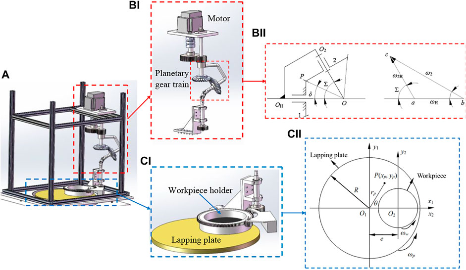
FIGURE 1. (A)Single-side planetary lapping machine with an irrational rotation speed ratio of the lapping plate to workpiece, (Bi) novel driving system design with planetary gear train and (Bii) its working mechanism; (Ci) single-side planetary lapping device and (Cii) its working mechanism.
It can also be seen from Figure 1Bii that in Δabc there are ba//OOH, ac//OO2, and bc//OP; thus, the relation between the input rotation speed, ωH, and the rotation speed of the bevel gear 2, ω2, can be obtained from the following equation:
By substituting Σ and δ into Eq. 2, the ratio of ω2 to ωH can be calculated as follows:
Therefore, the novel driving system designed in this study can be used to realize the irrational rotation speed ratio output, ω2, with respect to the input rotation speed, ωH.
In order to evaluate the lapping uniformity of the irrational rotation speed ratio driving system, the trajectory of any point P (rp, θp) fixed on the lapping plate moving along the target surface can be calculated according to the kinematics in Figure 1Cii which is given as follows:
Eq. 4 indicates that particle trajectories on the target surface are related to the rotation speed of the lapping plate, wp and the workpiece, ww, and the eccentric distance between O1 and O2, e. Thus, considering the experiment later in this study, the processing parameters in MATLAB are given in Table 1 to numerically investigate the distribution of particle trajectories on the target surface.
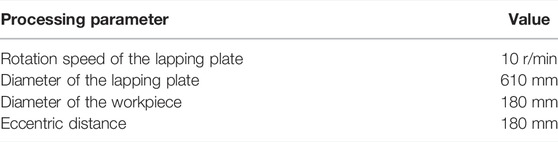
TABLE 1. Processing parameters in simulation.
As shown in Figure 2, 100 abrasive particles are randomly distributed on the lapping plate with a diameter of 610 mm, and their trajectories moving on the target surface have been numerically analyzed by considering the rational and irrational rotation speed ratios of the lapping plate to the workpiece, i, of 1:2 and
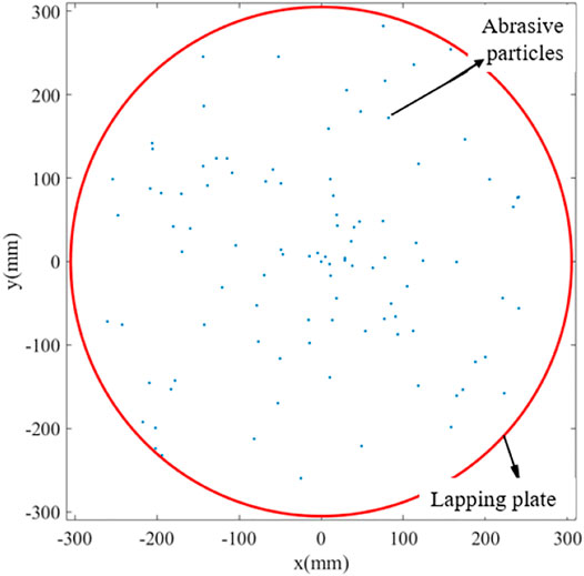
FIGURE 2. Random distribution of abrasive particles on the lapping plate.
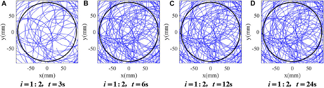
FIGURE 3. Distribution of particle trajectories on the target surface under i = 1:2. (A)

FIGURE 4. Distribution of particle trajectories on the target surface under
It can be found from Figure 3 that there is almost no variation in the distribution of particle trajectories on the target surface when the lapping time is from 6 to 24 s, which indicates that the particle trajectories generated by the rational rotation speed ratio, i = 1:2, should be periodically superposed with the increase in the lapping time. In contrast, it is noted from Figure 4 that with an increase in the lapping time, the coverage of particle trajectories on the target surface increases as well by employing the irrational rotation ratio,
Furthermore, the uniformity of particle trajectories on the target surface has also been quantitatively evaluated by considering the additional i of 1:1, 1:3, 2:3, 2:1, 3:1,
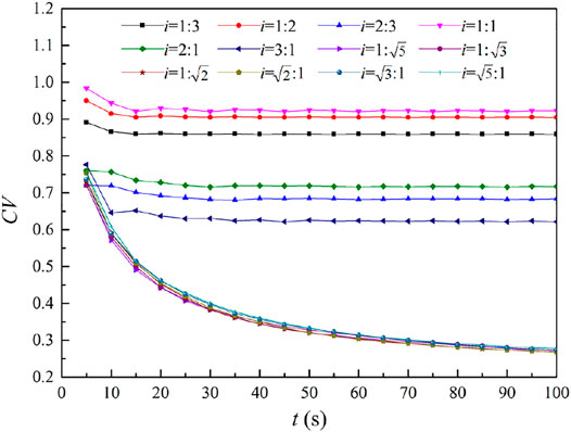
FIGURE 5. Comparison of CV under different values of i.
An in-house developed driving system based on the design in Section 2.1 has been designed to realize the irrational rotation speed ratio, and it is fixed in the YR610X single-side planetary lapping machine with the lapping plate diameter of 610 mm and the maximum lapping rotation speed of 300 r/min, as shown in Figure 6, where the traditional driving system to realize the rational rotation speed is also fixed in this machine to have a comparison in terms of surface form accuracy under the same processing parameters except the rotation speed ratio. Moreover, the single-crystal silicon wafer was selected as the workpiece with a diameter of 100 mm and thickness of 0.55 mm, and the processing parameters used in the experiment are given in Table 2. The workpiece was first roughly lapped using a P600 sandpaper (average diameter of 26 μm) for 10 min, and then, Al2O3 slurries with a concentration of 20% by mass and sizes of W14 (10–14 μm), W7 (5–7 μm), W3.5 (3–3.5 μm), W1.5 (1–1.5 μm), and W1 (0.5–1 μm) were used to conduct the precise lapping of the workpiece for 20, 20, 20, 10, and 10 min, respectively. After each test, the workpiece was measured with the assistance of the surface roughness measuring instrument Form Talysurf i60 and the wafer surface flatness measuring instrument ADE7200, and the values of total thickness variation (TTV), total indicated reading (TIR), site total indicated reading (STIR), curvature of the wafer (BOW), and warping deformation of the wafer (WARP) were obtained to evaluate the surface form accuracy.
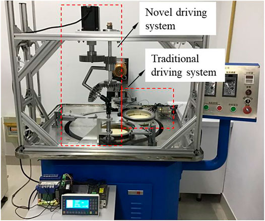
FIGURE 6. Experimental setup.
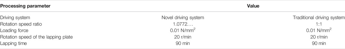
TABLE 2. Processing parameters in the experiment.
The overall surface morphology of the single-crystal silicon wafer after the abrasive lapping process is shown in Figure 7. By the qualitative comparison of surface morphology under the rotation speed ratios of i = 1 and i = 1.0772…, it is found from the resolution of the reflecting words on the target surface that there is no evident difference between i = 1 and i = 1.0772…, and a quantitative analysis on the average surface roughness by measuring 10 different positions on the target surface with respect to i = 1 and i = 1.0772… can be obtained using the surface roughness measuring instrument Form Talysurf i60, which are 11.2 and 7.62 nm, respectively. Thus, it can be deduced that the effect of the rational and irrational rotation speed ratios on the surface roughness is not significant, but its effect on the surface form accuracy that is related to the distribution of particle trajectories on the target surface still needs to be explored.
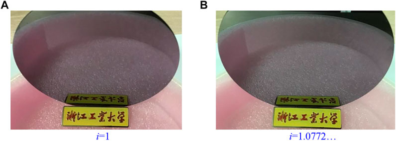
FIGURE 7. Comparison of surface morphology under different rotation speed ratios. (A) i=1 (B) i=1.0772…
Figure 8 shows the values of partial surface flatness, STIR, in the area of 15 mm × 15 mm under the rotation speed ratios of i = 1 and i = 1.0772…, respectively. It can be seen from Figure 7A that the maximum value of STIR is 9.02 μm under the rotation speed ratio of i = 1, while under the rotation speed ratio of i = 1.0772… the maximum value of STIR significantly reduces to be about 2.49 μm (Figure 8B), and its distribution on the target surface is more uniform than that with the rotation speed ratio of i = 1, which is well agreed with the simulation results, as discussed in Section 2.2.
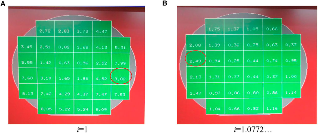
FIGURE 8. Distribution of partial surface flatness on the target surface under different rotation speed ratios. (A) i=1 (B) i=1.0772…
Furthermore, five essential values of TTV, TIR, STIR, BOW, and WARP, which are usually employed to evaluate the surface form accuracy (Satake et al., 2020) on the whole target surface are given in Table 3 under different conditions. In general, all the five essential values are better under the rotation speed ratio of i = 1.0772… than those under the rotation speed ratio of i = 1, which demonstrates that the irrational rotation speed of the ratio driving system has the advantage of being able to obtain a good surface form accuracy. It is also noticed that the variations of BOW and WARP are limited as compared between the original target surface and the lapping target surface, but the other values of TTV, TIR, and STIR present the significant change after the lapping process. Therefore, the surface form accuracy has been significantly improved by using the irrational rotation speed ratio realized by the novel driving system design in this study.

TABLE 3. Comparisons of surface form accuracy under different conditions.
Single-crystal silicon wafer is one of the commonly used materials in fabricating substrates of chips, and the surface quality of these substrates plays an important role in affecting their performance and service life. Thus, in this study, a novel driving system has been proposed to improve the uniformity of the particle trajectories moving on the target surface in the single-side planetary lapping process, and the main contributions are concluded as follows:
1) A novel driving system that consists of two bevel gears and a planetary carrier has been designed to realize the irrational rotation speed ratio, and its working mechanism has also been theoretically analyzed in detail.
2) It is found from numerically qualitative and quantitative studies that the particle trajectories generated by the rational rotation speed ratio are periodically superposed with the increase in the lapping time. In contrast, by employing the irrational rotation speed ratio, the particle trajectories would cover the whole target surface with the further increase in the lapping time because of the non-periodic characteristics. It indicates that the uniformity of the particle trajectories on the target surface can be significantly improved using the irrational rotation speed ratio and hence resulting in the higher surface form accuracy as well.
3) An in-house developed irrational rotation speed ratio driving system has been designed for the experimental study. It is found that the effect of the rational and irrational rotation speed ratios on the surface roughness is not significant, but all the five essential values related to the surface form accuracy are better under the rotation speed ratio than those under the rotation speed ratio, which demonstrates that the irrational rotation speed ratio driving system has the advantage of being able to obtain a good surface form accuracy and agrees well with the numerical simulation results.
Therefore, the novel driving system designed in this study to realize the irrational rotation speed ratio would provide good reference for the development of the abrasive lapping technology.
The raw data supporting the conclusion of this article will be made available by the authors, without undue reservation.
ZW and XW carried forward the design of the novel driving system. ZW conducted the numerical work, and XW carried out the experimental work. YL supervised this manuscript, prepared the original draft, and charged the review and editing of the manuscript.
This research was funded by the Education of Zhejiang Province under Grant No. Y202148174.
XW was employed by the company Zhejiang Zhongjing Technology Co., Ltd.
The remaining authors declare that the research was conducted in the absence of any commercial or financial relationships that could be construed as a potential conflict of interest.
All claims expressed in this article are solely those of the authors and do not necessarily represent those of their affiliated organizations, or those of the publisher, the editors, and the reviewers. Any product that may be evaluated in this article, or claim that may be made by its manufacturer, is not guaranteed or endorsed by the publisher.
The authors would like to acknowledge the support from the Zhejiang University of Technology for the measurements of the experimental results.
Belkhir, N., Bouzid, D., and Herold, V. (2009). Surface Behavior during Abrasive Grain Action in the Glass Lapping Process. Appl. Surf. Sci. 255, 7951–7958. doi:10.1016/j.apsusc.2009.04.178
Bu, Z., Niu, F., Chen, J., Jiang, Z., Wang, W., Wang, X., et al. (2022). Single crystal Silicon Wafer Polishing by Pretreating Pad Adsorbing SiO2 Grains and Abrasive-free Slurries. Mater. Sci. Semiconductor Process. 141, 106418. doi:10.1016/j.mssp.2021.106418
Burk, A. A., O'loughlin, M. J., Siergiej, R. R., Agarwal, A. K., Sriram, S., Clarke, R. C., et al. (1999). SiC and GaN Wide Bandgap Semiconductor Materials and Devices. Solid-State Electronics 43, 1459–1464. doi:10.1016/s0038-1101(99)00089-1
Cheng, Z., Qin, S., and Fang, Z. (2022). Numerical Modeling and Experimental Study on the Material Removal Process Using Ultrasonic Vibration-Assisted Abrasive Water Jet. Front. Mater. Accepted Publ. 9, 895271. doi:10.3389/fmats.2022.895271
Fang, C., Liu, C., Zhao, Z., Lin, Y., Hu, Z., and Xu, X. (2018). Study on Geometrical Patterns of Textured Fixed-Abrasive Pads in Sapphire Lapping Based on Trajectory Analysis. Precision Eng. 53, 169–178. doi:10.1016/j.precisioneng.2018.03.008
Hu, W., Teng, Q., Hong, T., Saetang, V., and Qi, H. (2022). Stress Field Modeling of Single-Abrasive Scratching of BK7 Glass for Surface Integrity Evaluation. Ceramics Int. 48 (9), 12819–12828. doi:10.1016/j.ceramint.2022.01.153
Ji, R., Zhang, L., Zhang, L., Li, Y., Lu, S., and Fu, Y. (2022). Processing Method for Metallic Substrate Using the Liquid Metal Lapping-Polishing Plate. Front. Mater. Submitted for publication 9, 896346. doi:10.3389/fmats.2022.896346
Li, C., Piao, Y., Meng, B., Hu, Y., Li, L., and Zhang, F. (2022). Phase Transition and Plastic Deformation Mechanisms Induced by Self-Rotating Grinding of GaN Single Crystals. Int. J. Machine Tools Manufacture 172, 103827. doi:10.1016/j.ijmachtools.2021.103827
Li, H. N., Yang, Y., Zhao, Y. J., Zhang, Z., Zhu, W., Wang, W., et al. (2019). On the Periodicity of Fixed-Abrasive Planetary Lapping Based on a Generic Model. J. Manufacturing Process. 44, 271–287. doi:10.1016/j.jmapro.2019.05.036
Lu, Y., Shu, Q., Wang, J., and Liu, Y. (2014). A Kinematical Analysis of the Polishing Processes of Hard Magnetic Disk Substrate. Proc. Inst. Mech. Eng. B: J. Eng. Manufacture 228, 215–222. doi:10.1177/0954405413498073
Niitsu, K., and Yan, J. (2020). Effects of Deep Subsurface Damages on Surface Nanostructure Formation in Laser Recovery of Grinded Single-crystal Silicon Wafers. Precision Eng. 62, 213–222. doi:10.1016/j.precisioneng.2019.12.005
Qi, H., Shi, L., Teng, Q., Hong, T., Tangwarodomnukun, V., Liu, G., et al. (2022). Subsurface Damage Evaluation in the Single Abrasive Scratching of BK7 Glass by Considering Coupling Effect of Strain Rate and Temperature. Ceramics Int. 48, 8661–8670. doi:10.1016/j.ceramint.2021.12.077
Sanchez, L. E. A., Jun, N. Z. X., and Fiocchi, A. A. (2011). Surface Finishing of Flat Pieces when Submitted to Lapping Kinematics on Abrasive Disc Dressed under Several Overlap Factors. Precision Eng. 35, 355–363. doi:10.1016/j.precisioneng.2010.09.012
Satake, U., Matsui, S., and Enomoto, T. (2020). Polishing Pad for Reducing Edge Roll-Off while Maintaining Good Global Flatness of Silicon Wafer. Precision Eng. 66, 577–592. doi:10.1016/j.precisioneng.2020.09.010
Tam, H.-y., and Cheng, H. (2010). An Investigation of the Effects of the Tool Path on the Removal of Material in Polishing. J. Mater. Process. Technology 210, 807–818. doi:10.1016/j.jmatprotec.2010.01.012
Uhlmann, E., List, M., Patraschkov, M., and Trachta, G. (2018). A New Process Design for Manufacturing Sapphire Wafers. Precision Eng. 53, 146–150. doi:10.1016/j.precisioneng.2018.03.011
Wen, D., Qi, H., Ma, L., Lu, C., and Li, G. (2016). Kinematics and Trajectory Analysis of the Fixed Abrasive Lapping Process in Machining of Interdigitated Micro-channels on Bipolar Plates. Precision Eng. 44, 192–202. doi:10.1016/j.precisioneng.2015.12.005
Yang, Y., Li, H., Liao, Z., and Axinte, D. (2019). A Curious Observation of Phenomena Occurring during Lapping/polishing Processes. Proc. Math. Phys. Eng. Sci. 475, 20190304. doi:10.1098/rspa.2019.0304
Yuan, J., Yao, W., Zhao, P., Lyu, B., Chen, Z., and Zhong, M. (2015). Kinematics and Trajectory of Both-sides Cylindrical Lapping Process in Planetary Motion Type. Int. J. Machine Tools Manufacture 92, 60–71. doi:10.1016/j.ijmachtools.2015.02.004
Zhang, L., Zheng, B., Xie, Y., Ji, R., Li, Y., and Mao, W. (2022). Control Mechanism of Particle Flow in the Weak Liquid Metal Flow Field on Non-uniform Curvature Surface Based on Lippmann Model. Front. Mater. Accepted Publ. 9, 895263. doi:10.3389/fmats.2022.895263
Zhang, P., Feng, X., and Yang, J. (2015). Kinematics Analysis on the Double-Sided Polishing without Planet Carrier of 3 Inch SiC Substrate. J. Funct. Mater., 18105–18111.
Keywords: surface form accuracy, single-side planetary lapping, irrational rotation speed ratio, particle trajectories, uniform distribution
Citation: Wang Z, Lei Y and Wu X (2022) Surface Form Accuracy Evaluation in Abrasive Lapping of Single-Crystal Silicon Wafers. Front. Mater. 9:901556. doi: 10.3389/fmats.2022.901556
Received: 22 March 2022; Accepted: 08 April 2022;
Published: 10 May 2022.
Edited by:
Guijian Xiao, Chongqing University, ChinaReviewed by:
Zhengquan Li, Jiangxi University of Science and Technology, ChinaCopyright © 2022 Wang, Lei and Wu. This is an open-access article distributed under the terms of the Creative Commons Attribution License (CC BY). The use, distribution or reproduction in other forums is permitted, provided the original author(s) and the copyright owner(s) are credited and that the original publication in this journal is cited, in accordance with accepted academic practice. No use, distribution or reproduction is permitted which does not comply with these terms.
*Correspondence: Yang Lei, bGVpeWFuZ2NuQDEyNi5jb20=
Disclaimer: All claims expressed in this article are solely those of the authors and do not necessarily represent those of their affiliated organizations, or those of the publisher, the editors and the reviewers. Any product that may be evaluated in this article or claim that may be made by its manufacturer is not guaranteed or endorsed by the publisher.
Research integrity at Frontiers
Learn more about the work of our research integrity team to safeguard the quality of each article we publish.