 Yujie Zhang
 Junping Zhang
 Bingcong Chen3*
- 1College of Urban and Rural Construction, Zhongkai University of Agriculture and Engineering, Guangzhou, China
- 2Earthquake Engineering Research and Test Center, Guangzhou University, Guangzhou, China
- 3Research Center for Wind Engineering and Engineering Vibration, Guangzhou University, Guangzhou, China
- 4College of Urban Construction, Heze University, Heze, China
Steel and steel-fiber-reinforced concrete (SFRC) composite beams with high-strength friction-grip bolt (HSFGB) connectors have been found to improve the shear behavior of HSFGBs and enhance the potential application of composite beams. In order to evaluate the shear force transmission mechanism of HSFGBs in steel-SFRC beams, finite element models (FEMs) developed by ABAQUS software had been carefully developed to evaluate force transmission and failure mechanisms of HSFGBs. Shear behavior differences between conventional studs and HSFGBs were also studied. Then according to the orthogonal statistics method, FEMs were further modified to explore significant influencing factors affecting HSFGB shear performance. The results showed that pretension degree was the main factor affecting the shear performance of HSFGBs at serviceability limit states, while HSFGB diameter was the most important factor affecting stiffness and ultimate shear strength at ultimate limit state.
1 Introduction
Due to their outstanding properties such as favorable mechanical characteristics, easy construction, and beneficial economic performance, steel-concrete composite beams have been extensively applied in engineering for many years (Brozzetti, 2000; Nakamura et al., 2002). As an important component of composite beams, shear connectors directly affect the overall performance of composite beams. Generally, stud connectors are applied to transmit joint action between the steel beam and concrete slabs (Oehlers and Bradford, 1995). However, conventional headed stud connectors welded onto steel beams and cast into concrete slabs limit the repairability of composite beams. Furthermore, shrinkage and creep of cast-in-place concrete slabs connected by headed studs might result in the increase of composite beam deformation, greatly affecting the long-term performance of composite structures (Johnson, 2006; Ban et al., 2015).
One way to address these issues is the application of HSFGBs as shear connectors in composite beams due to their advantages of high strength and stiffness, tight connection, and convenience of dismantling. However, due to the lower load at initial slip and cracking of concrete slabs (Zhang et al., 2019), HSFGB properties may not be fully developed. Meanwhile, steel-fiber-reinforced concrete (SFRC) specimens fabricated by the addition of steel fibers into normal concrete have superior tensile strength and favorable ductility (Khaloo and Afshari, 2005; Taniguchi et al., 2007), can effectively control crack development. Also, the application of SFRC in the negative bending moment region of continuous composite beams not only effectively restrained the crack width in slabs but also improved the ultimate capacity of composite beams (Lius et al., 2006; Abas et al., 2013; Lin et al., 2016). Therefore, the application of SFRC with high tensile strength and crack resistance in composite beams was found to improve the shear behavior of HSFGBs and enhance the potential application of composite beams. Due to the abovementioned advantages, these innovative composite beams with HSFGBs can be extended to the rapid construction of small and medium span bridges, as well as steel-concrete composite flooring systems.
Dallam (1968) and Harpster (Dallam and Harpster, 1968) performed static push-out tests on steel-concrete composite specimens connected by the HSFGBs. The test results revealed that the ultimate load of HSFGB connectors was higher than that of studs. Dedic and Klaiber (1986) studied the behaviors of HSFGBs to reinforce existing non-composite bridges. The obtained test results showed that HSFGBs could increase the strength of non-composite bridges. Pavlović et al. (2013) performed experimental tests and numerical analyses on HSFGBs and found that although they had sufficient shear strength, their shear stiffness was lower than that of headed studs. Kwon et al. (2010; 2011) evaluated the application of HSFGBs with embedded nuts in prefabricated concrete slabs and found that HSFGBs had a lower shear capacity and initial stiffness than headed studs. [Liu et al., (2015); Liu and Bradford, (2016)] performed a series of research works on the shear behavior of HSFGBs. However, they noted undesirable large slips, which negatively affected the shear stiffness of bolts. Zhang et al. (2019) studied the shear behavior of HSFGBs and found that the shear capacity and stiffness of bolted connectors were reduced due to the cracks in concrete slabs. Recently, Ataeiet et al. (2019) reported that increasing the size and strength of single-nut bolts enhanced initial stiffness, ultimate shear strength, ductility, and energy dissipation capacity. Furthermore, HSFGBs have been applied for connecting the steel beams and precast ultra-high-performance concrete (Fang et al., 2020; Fang et al., 2021; Fang et al., 2022) and it has been found that HSFGBs improved the performance of composite beams with ultra-high-performance concrete.
Among previous research works reported in the literature, most studies have focused on the factors influencing the ultimate shear capacity of HSFGBs at the ultimate limit state (Kwon et al., 2010; Liu et al., 2015; Liu and Bradford, 2016; Fang et al., 2020; Zhang et al., 2020). However, HSFGBs are employed to connect steel beams and concrete slabs by applying pretension. In addition, the interfacial shear force is transmitted through the friction generated by HSFGB pretension at the initial loading stage which is then transmitted through extrusion between bolts and concrete slabs [GB/T 3632-2008, 2008/T 3632-2008 (2008). Na, 2008] Therefore, it was necessary to investigate the shear performance of HSFGBs at initial loading and ultimate limit stages. It is of pivotal importance to obtain the transmission regularity of shear force for the design of HSFGBs in steel-concrete composite beams. Therefore, studying deeply shear transfer mechanism of HSFGBs has important theoretical and engineering value. However, little research has been conducted on the force transmission mechanism of HSFGBs in composite beams. Therefore, effective finite element models (FEMs) were developed to investigate the load transfer and failure mechanisms as well as significant influencing factors on the shear behaviors of HSFGBs.
2 Finite Element Analysis
FE method was applied to further investigate the shear performance and force transmission mechanism of HSFGB connections in SFRC specimens. To obtain accurate numerical results, all components including concrete slabs, steel beams, bolted connectors, reinforcing bars, and washers were appropriately modeled in FE analyses. Both geometrical and material nonlinearities were taken into account.
2.1 Finite Element Modeling
2.1.1. Numerical Models
The 3D FEMs of specimens were established by using finite element analysis software ABAQUS. As shown in Figure 1, one-quarter of each specimen was simulated by applying symmetric constraints on a symmetric surface. In the developed FEMs, concrete slabs, bolts, washers, and structural steel beams were simulated by 3D eight-node linear hexahedral solid element (C3D8R) in ABAQUS. Reinforcing bars were modeled by 3D truss elements (T3D2). Surface-to-surface contact interaction was applied at all interfaces by setting contact pairs, as shown in Figure 2. Hard contact was applied for normal behavior, while tangential behavior was supposed as a penalty option. The reinforcement bars were embedded in a concrete slab, as described in Figure 2C (Han et al., 2015).
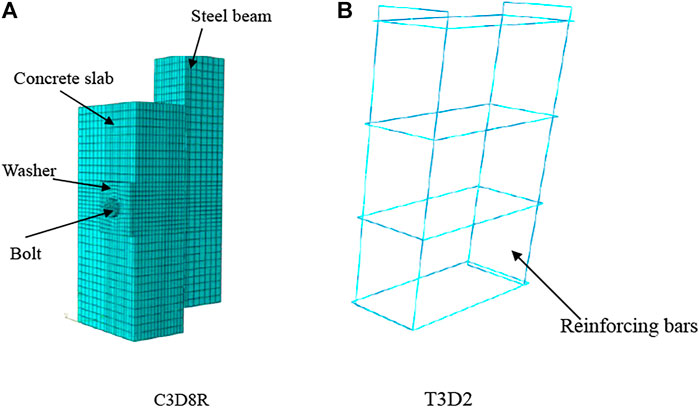
FIGURE 1. Details of the developed FEMs.
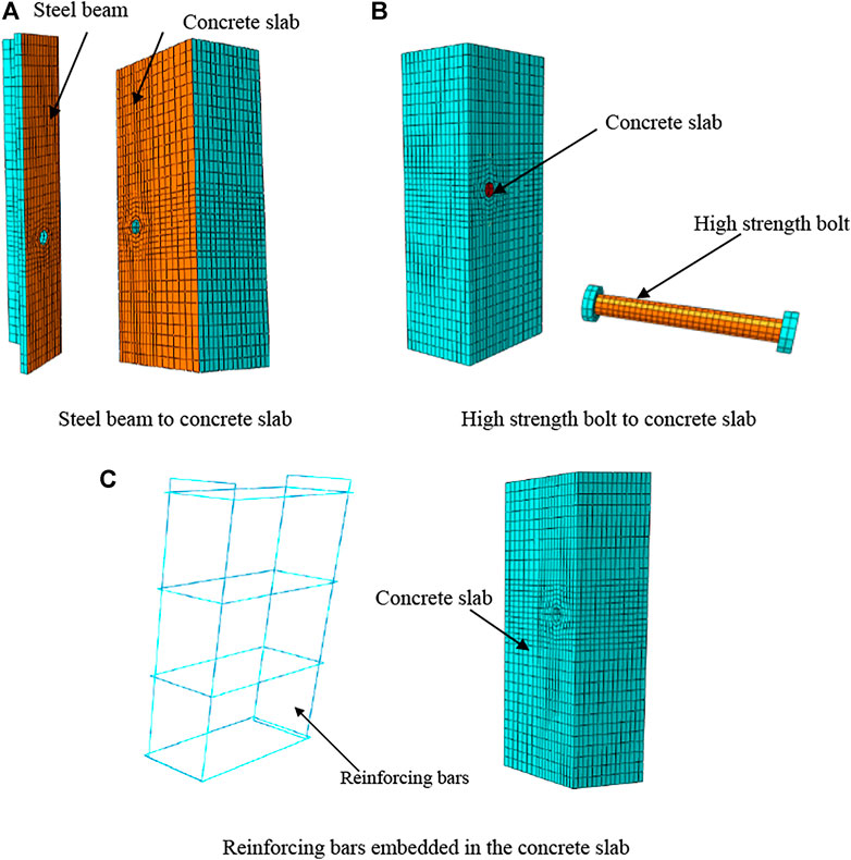
FIGURE 2. Contact details of the developed FEMs.
To prevent out-of-plane deformations, symmetric planes (surfaces 1 and 3) were set as symmetric boundary conditions, and the bottom of the concrete slab (surface 2) was completely restrained (Wang et al., 2021). Displacement loading was applied on the top of the steel beam, as shown in Figure 3.
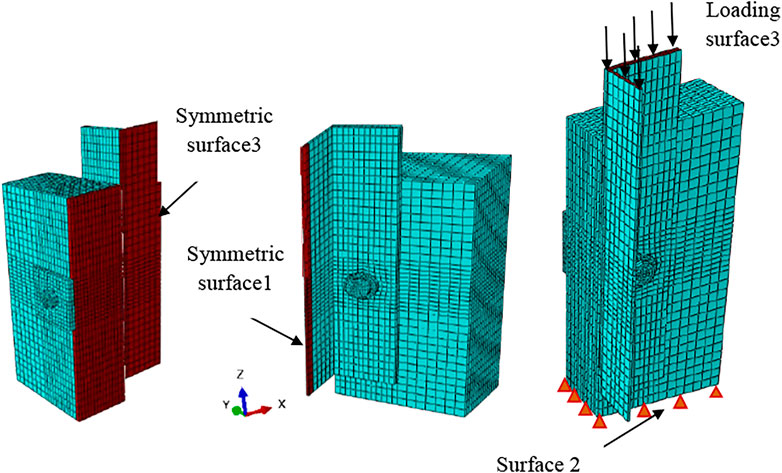
FIGURE 3. Boundary conditions and loading surfaces.
2.1.2 Material Properties
2.1.2.1 Steel
The stress-strain relationship introduced by Zhang et al. (2020) was applied to represent the constitutive behaviors of HSFGBs. The stress-strain behaviors of steel plates and rebar were supposed to be elastic.
2.1.2.2 Concrete
Concrete behavior was modeled by the concrete damaged plasticity (CDP) model in ABAQUS.Figure 4 shows equivalent uniaxial stress-strain curves, which were applied to describe the nonlinear characteristics of SFRCs.
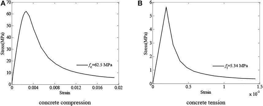
FIGURE 4. Stress-strain curves of SFRC
The uniaxial stress-strain relationship suggested by Gao (1991a; 1991b) was applied to simulate SFRC behavior which was expressed as
and
where
where
2.2 Validation of Numerical Results
In order to validate the accuracy of the finite element model developed, the push-out specimens with HSFGB tested by Zhang et al. (2020) have been analyzed. Figure 5 shows specimen dimensions. The length, depth, and width of concrete slabs were 450, 120, and 440 mm, respectively (British Standards Institu, 2006). In each specimen, concrete slabs and steel beams were connected with four bolts, as presented in Figure 5. Bars 10 mm in diameter were applied as transverse and longitudinal reinforcements to prevent slab splitting. 500 mm long Q345 steel with a Chinese HW200 × 200×8/12 mm section was used as a steel beam.
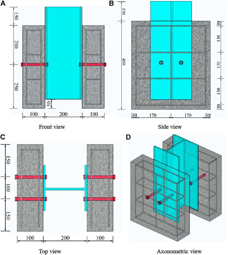
FIGURE 5. Configurations of test specimens.
At the initial phase of the loading process of HSFGBs, the shear force was mainly transmitted through interfacial friction. In this stage, the load-slip curve was linear which could be defined as a serviceability limit state. By the increase of load, the shear force was mainly transmitted through the force generated by the extrusion of bots and concrete slabs, where load-slip curves presented a nonlinear trend and stiffness became lower than that at serviceability limit states. This stage could be defined as an ultimate limit state. In order to systematically investigate HSFGB shear performance, the initial slip force V0, the ultimate capacity of HSFGBs Vu, post-slipping stiffness Ks, and ultimate slipping Su were defined as referred to reference (Zhang et al., 2020). The initial shear stiffness K0 of HSFGBs was defined as the ratio of slip resistance load to corresponding slip value. HSFGB mechanical properties at serviceability limit state could be evaluated by initial slip force V0 and initial shear stiffness K0, while its mechanical properties at ultimate limit state could be evaluated by ultimate capacity Vu, ultimate slipping Su, and post-slipping stiffness Ks.
Figure 6 a to d present the load-relative slip curves of tested specimens and the results predicted by FEM. In these figures, linear properties measured by FEM agreed well with the experimental results. However, the nonlinear response was slightly different. The reason for these differences was that the constitutive inhomogeneity of concrete was simplified in FE analyses. The accuracy range of force V0 at initial slip between numerical and experimental results was 2.78%. Also, the accuracy range of initial shear stiffness K0 between numerical and experimental results was 6.08%. The maximum difference between post-slipping stiffness Ks between numerical and experimental results was 9.73%, while the maximum difference between numerical and experimental values of ultimate capacity VU was 9.93%. Although there were some differences between numerical and experimental results, load-slip curves obtained by both methods agreed well, demonstrating that numerical models could be used for the evaluation of HSFGB shear behavior with good precision.
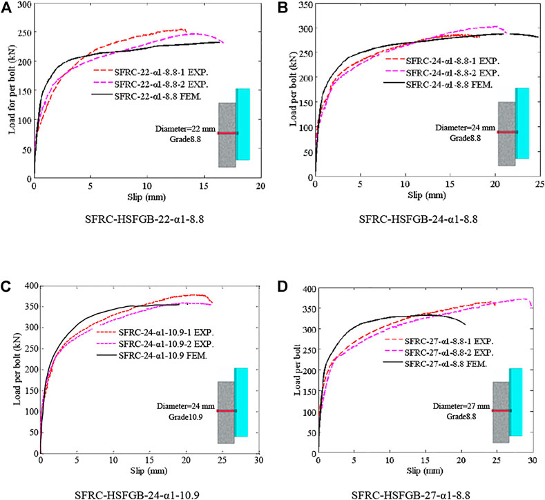
FIGURE 6. Comparison of the numerical and tested results obtained for load-relative slip relationship.
3 Comparison of the Shear Performance of Different Shear Connectors
The effect of shear connector type is shown in Figure 7. Two shear connector types were considered in this work: conventional headed studs and HSFGBs with a diameter of 22 mm. Figure 6 compares load-relative slip curves of headed studs and HSFGBs. It was clearly observed that the load-relative slip curves of specimens with headed studs presented three distinct stages of linear stage (OP), nonlinear stage (PM), and descending stage (MN) while those of specimens with HSFGBs showed four distinct stages of almost no slipping stage (OA), linear stage (AB), nonlinear stage (BC), and descending stage (CD). The initial slip force in HSFGBs was more obvious than that in the headed studs due to the existence of pretension in HSFGBs. The ultimate slipping of HSFGBs was higher than that of conventional-headed studs. The ultimate capacity of headed studs and HSFGBs were 238.9 and 242.8 kN, respectively, indicating their comparable ultimate shear capacity.
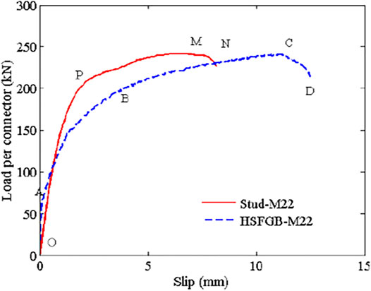
FIGURE 7. Comparison of the shear performance of different shear connectors.
4 Analysis of the Force Transmission Mechanism of High Strength Friction Grip Bolts
Shear failure of bolts in specimens with 22 mm grade 8.8 bolts and crushing failure of concrete slabs in specimens with 24 mm grade 10.9 bolts were observed in tests performed by Zhang et al. (2020). Hence, based on FEM results, taking specimens SFRC-HSFGB-22-α1-8.8 and SFRC-HSFGB-24-α1-10.9 as examples, internal stress distribution, as well as failure initiation and development in HSFGBs and concrete slabs in different specimens was studied and then, the force transmission mechanism, of HSFGBs was evaluated under two different failure modes.
HSFGB at the steel-concrete interface was critical during the loading process. As shown in Figure 8, bolts at the steel-concrete interface were marked as J and those at the end of concrete slabs were marked as Q. Meanwhile, the tensile and compression zones of concrete slabs were respectively marked as T and R.
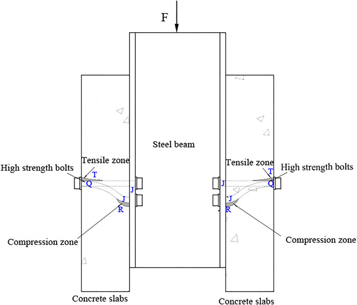
FIGURE 8. Schematic diagram of the critical areas of HSFGBs and concrete slabs.
Figure 9A shows the stress-load curves of the J zones of HSFGBs in SFRC-HSFGB-M22-α1-8.8 and SFRC-HSFGB-24-α1-10.9 specimens. Figure 9B presents the maximum principal stress-load curves of the T zones of concrete slabs in the abovementioned two specimens. Figure 10 shows the typical load-slip curves of HSFGBs in the above two specimens. As shown in Figure 9A, the stress-load curves of the J zones of HSFGBs experienced four distinct stages: friction transferring force stage, bolt shank elastic transferring force stage, bolt shank plastic transferring force stage, and failure stage. In the friction transferring force stage (OA segments), tensile stress in the J zones of HSFGBs remained unchanged and external load was balanced by the friction force due to the pretension applied in bolts. When maximum friction force was exceeded, the stress in J zones was increased gradually until yield strength was reached, as shown in AB segments (bolt shank elastic transferring force stage) in Figure 9A. As the load was increased, the stress in J zones was increased to its tensile strength, as presented in BC segments (bolt shank plastic transferring force stage) in Figure 9A. Then, the stress in J zones was maintained constant at tensile strength until specimens failed, as presented in CD segments (failure stage) in Figure 9A.

FIGURE 9. The stress-load curves of HSFGBs and concrete slabs in specimens.
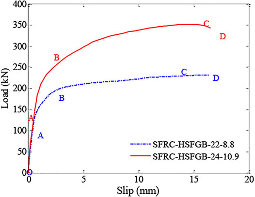
FIGURE 10. The load-slip curves of HSFGBs in different specimens.
4.1 Stress Analysis for the Force Transmission Mechanism of High-Strength Friction-Grip Bolts Under Bolts Shear off Failure
Figure 11 shows the changes in the Mises stress of HSFGBs and the maximum principal stress of concrete slabs in specimen SFRC-22-α1-8.8 during the whole loading process. For specimen SFRC-22-α1-8.8, at the beginning of loading, due to the pretension applied to HSFGBs, the Mises stress of HSFGBs was uniformly distributed along the bolt with an approximate value of about 350 MPa (Figure 11A) which was lower than its yield strength, while the concrete slabs around the bolts were compressed with 2.5 MPa stress (Figure 11B). Meanwhile, little relative slip between steel and concrete plates occurred, as described in the OA parts of the curves in Figure 10. When load value exceeded pretension-generated friction or reached initial slip V0 force, the serviceability limit state ended. As the load was increased to140 kN (about 0.6VU), HSFGB stress was unevenly distributed along the bolts and gradually decreased from J end to Q end (Figure 11B). HSFGB stress at the J end was about 620 MPa, which was close to yield strength. The maximum principal stress of concrete slabs was 2.10 MPa, which was lower than tensile strength. Hence, HSFGB yield was considered as the end of bolt shank elastic transferring force stage in these specimens. And relative slippage was linearly increased with the increase of load (Figure 10 AB segments). Then, HSFGB stress at the J end was increased by increasing the load from 140 kN (about 0.6Vu) to 240.5 kN (about Vu). HSFGB deformation was limited due to the constraints of surrounding steel plates and concrete slabs and stress at the J end quickly reached the tensile strength of 840 MPa (Figure 11C). However, the relative slip was increased with the increase of load and the relative slip growth rate was greater than the load growth rate, as described in the BC parts of the curves in the Figure 10. Then, relative slip continued to increase and the load was slightly decreased (Figure 10 CD segments) until HSFGBs were sheared off at the interface of steel plates and concrete slabs.
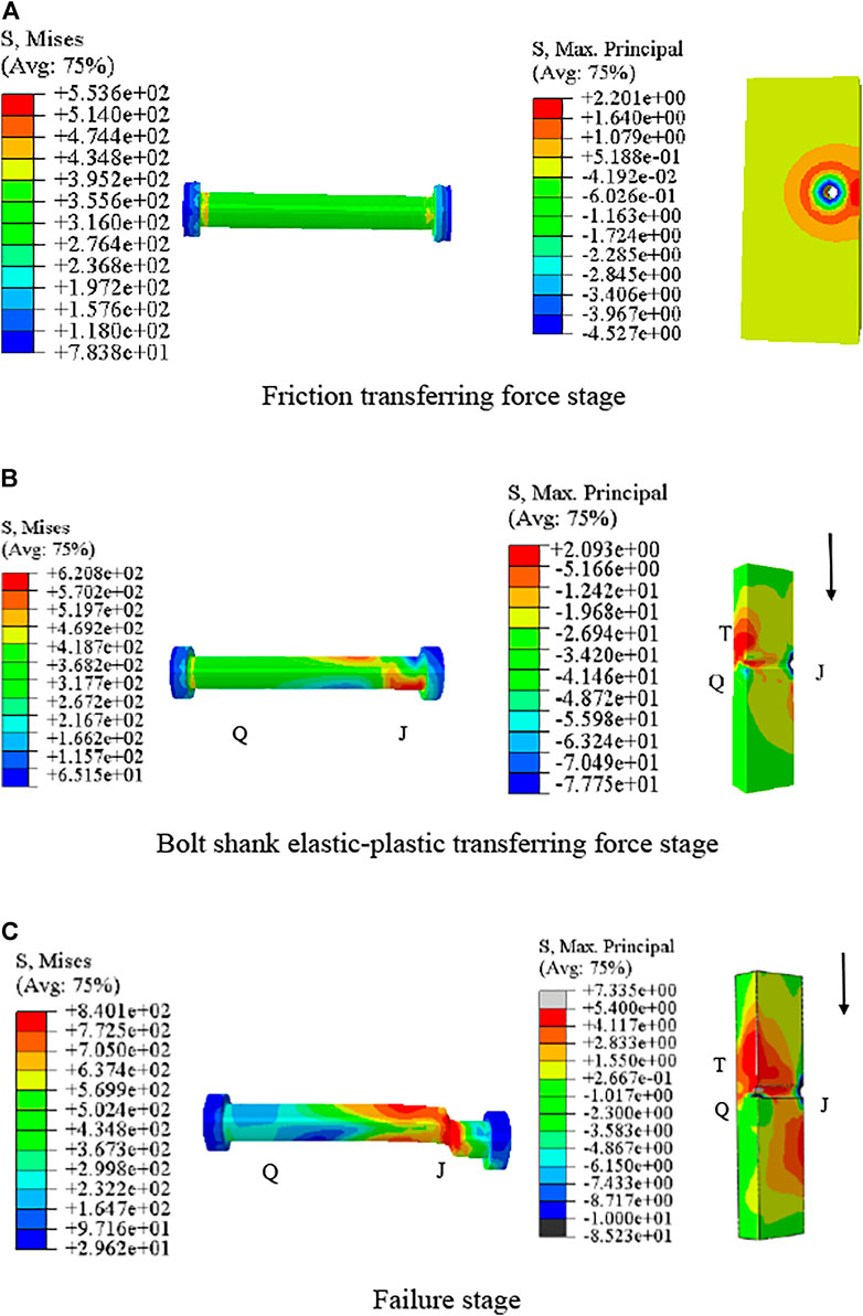
FIGURE 11. Stress distribution in HSFGBs and concrete slabs in SFRC-22-α1-8.8 specimen(MPa).
4.2 Stress Analysis of the Force Transmission Mechanism of High-Strength Friction-Grip Bolts Under Concrete Splitting Failure
At the serviceability limit state, Mises stress in HSFGBs was uniformly distributed along the bolts in the SFRC-24-α1-10.9 specimen, which was similar to that of the SFRC-22-α1-8.8 specimen. Also, little relative slip between steel and concrete plates occurred (Figure 10 OA segments). However, for the SFRC-24-α1-10.9 specimen, by the increase of load to 240 kN (about 0.7Vu), HSFGB stress was unevenly distributed along the bolts and gradually decreased from J end to Q end (Figure 12A). HSFGB stress at J end was about 745 MPa which was lower than yield strength. Concrete slab stress was 5.46 MPa (Figure 12B), which was close to tensile strength. And the relative slip grew gradually and linearly. Therefore, the formation of concrete cracks was considered as the end of the bolt shank elastic transferring force stage for this specimen. HSFGB stress at the J end was increased by increasing load from 240 kN (about 0.7Vu) to 365 kN (about Vu), and stress in concrete slabs reached tensile strength, resulting in concrete splitting failure while HSFGB maximum stress was about 1122 MPa, indicating that HSFGBs were under bending and shearing deformation, but not sheared off.
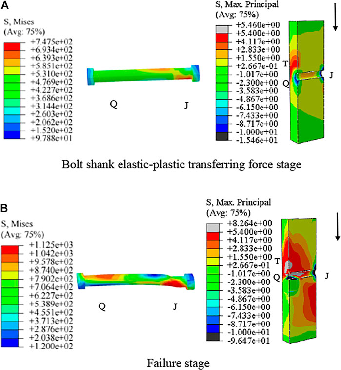
FIGURE 12. Stress distribution in HSFGBs and concrete slabs in SFRC-24-α1-10.9 specimen (MPa).
In summary, the force transfer process of HSFGBs in steel-SFRC push-out specimens was as follows: 1) friction transferring force stage or serviceability limit state: when the load was lower than V0, load transferred by interface friction due to pretension and HSFGB stress was uniformly distributed along the bolts, while concrete slabs around the bolts were compressive with small slip between steel plates and concrete slabs. When load reached initial slip force V0, the end of serviceability limit state was reached. 2) Bolt shank elastic transferring force stage: when load was increased to 0.6–0.7Vu, HSFGB stress was unevenly distributed along the bolts and tensile stress was also increased in concrete slabs. HSFGB yield or concrete crack were regarded as the end of bolt shank elastic transferring force stage. 3) Bolt shank plastic transferring force stage: HSFGB stress was quickly increased to tensile strength and concrete stress was continuously increased as the load was increased from 0.6–0.7 Vu to Vu. 4) Failure stage: concrete crushing-splitting and bolt bending failures were more evident specimens when the diameter of HSFGB was large or tensile strength was high. Otherwise, bolt stress reached tensile strength resulting in shear fracture failure of the bolt.
5 The Sensitivity Degrees of Factors on the Shear Performance of High-Strength Friction-Grip Bolts
5.1 Parameters
The previous results obtained by Zhang et al. (2020) showed that the main four factors affecting the HSFGB shear performance included concrete compressive strength (A), bolt diameter (B), tensile strength (C), and pretension (D). Due to several influencing factors and limited test conditions, it was difficult to conduct comprehensive tests. Therefore, the orthogonal statistics method was adopted to analyze the sensitivity of each influencing factor in HSFGB shear performance.
Generally, the diameters of HSFGBs applied in railway bridges and large factories are 20 and even 27 mm. Therefore, HSFGBs with diameters 20, 22, 24, and 27 mm were adopted to evaluate the influence of diameter on HSFGB shear performance. Grade 8.8 and 10.9 HSFGBs with tensile strengths of not less than 830 MPa are recommended to be applied in civil engineering. Different degrees of bolt pretension, i.e., 0.4, 0.6, 0.8, and 1, were adopted to investigate the influence of pretension on HSFGB shear performance. Concrete strength generally varies in the range of 40–70 MPa, which is commonly applied in steel-concrete composite structures. Therefore, four dimensions of each factor L16 (44) were adopted in orthogonal design, as listed in Table 1.
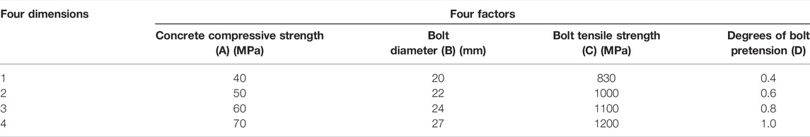
TABLE 1. Four factors and four dimensions of orthogonal design.
5.2 Analysis of Numerical Results
The numerical results obtained for each group are summarized in Table 2. For example, A1B1C1D1 represents the compressive strength of the concrete slab in this sample is 40MPa, while the diameter, tensile strength, and degrees of pretension of HSFGB are 20 mm, 830 MPa, and 0.4, respectively.
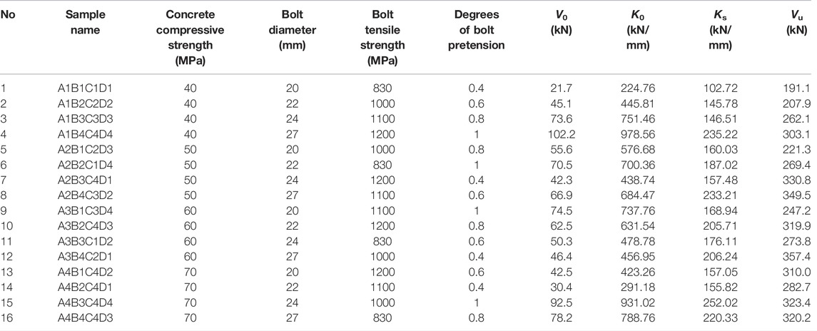
TABLE 2. The summary of numerical samples and results.
The total evaluation index was used for analysis by statistical method to investigate the influence of each parameter on the shear behavior of HSFGBs. wi is the average value of numerical results obtained at the dimension i of the factors in any column, which was used to intuitively determine the degree of influence of each factor on the performance of HSFGBs as shown in Figures 13–16 .The analysis of variance was performed by statistical software and the results are listed in Tables 3–6, where R is the range value of numerical results, while the values of
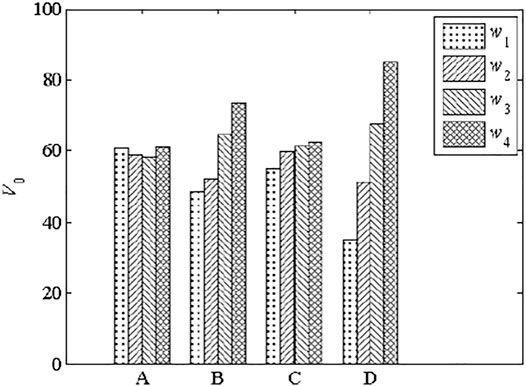
FIGURE 13. Influence of the four factors on the initial slip force of HSFGBs.
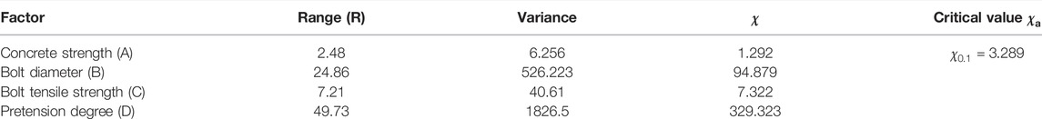
TABLE 3. Range and variance analysis results of the initial slip force of HSFGBs.
5.2.1 The Sensitivity Degree of Each Factor to Force at Initial Slip of High-Strength Friction-Grip Bolts
Figure 13 shows that the average force at initial slip was increased with the increase of the diameter (B), tensile strength (C), and pretension degree (D) of HSFGBs, but was not significantly affected by concrete strength.
Table 3 lists the range and variance analysis results of the initial slip force of HSFGBs. The ranges of pretension degree, diameter, and tensile strength of HSFGBs were 49.73, 24.86, and 7.21, respectively, while the
5.2.2 The Sensitivity Degree of Each Factor to Initial Shear Stiffness
Figure 14 shows that average initial shear stiffness was increased by increasing bolt diameter (B), tensile strength (C), and pretension degree (D) but was not significantly affected by concrete strength.
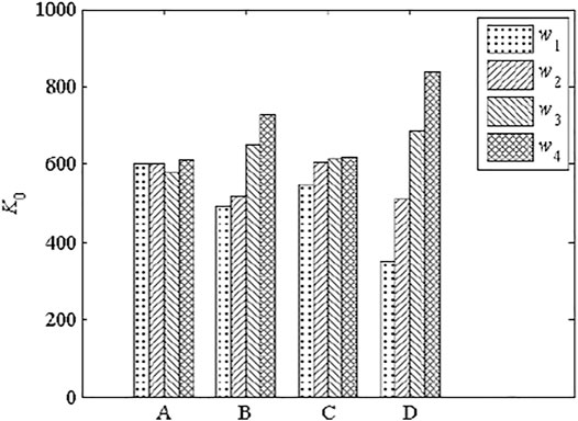
FIGURE 14. Influence of the four factors on initial shear stiffness.
Table 4 summarizes the results of range and variance analyses of initial shear stiffness. The ranges of bolt pretension degree, diameter, and tensile strength were 484.02, 236.57, and 69.86, respectively, while the
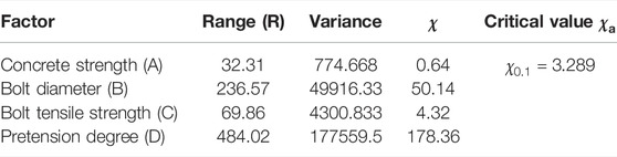
TABLE 4. Results of range and variance analyses of initial shear stiffness.
5.2.3 The Sensitivity Degree of Each Factor to Post-slip Stiffness of High-Strength Friction-Grip Bolts
Figure 15 shows that post-slip stiffness was increased by increasing the bolt diameter (B), pretension degree (D), and concrete strength (A), but was not significantly affected by tensile strength (C). Table 5 summarizes the results of range and variance analyses of post-slip stiffness. The ranges HSFGB pretension degree and diameter, as well as concrete strength, were 55.23, 76.56, and 38.75, respectively, while the
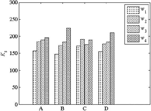
FIGURE 15. Influence of the four factors on the post-slip stiffness of HSFGBs.
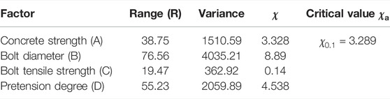
TABLE 5. Range and variance analysis results of the post-slip stiffness of HSFGBs.
5.2.4 The Sensitivity Degree of Each Factor to the Ultimate Capacity of High-Strength Friction-Grip Bolts
Figure 16 shows that ultimate capacity was increased by increasing bolt diameter (B) and tensile strength (C) as well as concrete strength (A), but was not significantly affected by pretension degree (D). Table 6 lists the results of range and variance analyses of ultimate capacity. The ranges of bolt tensile strength and diameter as well as concrete strength were 52.31, 90.11, and 68.06, respectively, while the
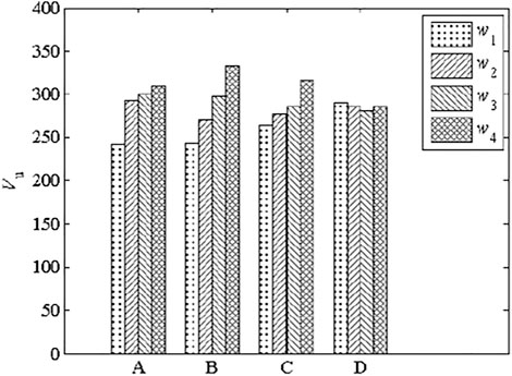
FIGURE 16. Influence of the four factors on the ultimate capacity of HSFGBs.
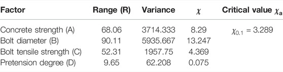
TABLE 6. Range and variance analysis results of the ultimate capacity of HSFGBs.
Consequently, the sensitivity degree to each of these factors affecting the shear performance of HSFGBs was different. In general, pretension degree was the main factor affecting the shear performance of HSFGBs at serviceability limit states, while HSFGB diameter was the most important factor affecting stiffness and ultimate shear strength at ultimate limit state. From this perspective, it was important to control pretension loss through the application of double nuts and spring tightening. Additionally, HSFGBs with large diameter and high strength grade could improve the initial slip force, initial shear stiffness, and ultimate capacity of HSFGBs.
6 Conclusion
An accurate and reliable 3D finite element model has been developed to investigate the shear force transmission mechanism of HSFGBs in steel-SFRC composite beams. The following main conclusions were drawn.
1) Compared with the shear behavior of headed studs, the initial slip force of HSFGBs was more obvious due to the existing pretension of HSFGBs. At ultimate limit state, the ultimate capacities of headed studs and HSFGBs were approximate.
2) According to numerical results, the force transfer process of HSFGB steel-steel fiber reinforced concrete push-out specimens occurred as follows: 1) Friction transferring force stage or serviceability limit state: load reached to initial slip force V0 which indicated the end of serviceability limit state. 2) Bolt shank elastic transferring force stage: HSFGB yield or concrete crack were regarded as the end of bolt shank elastic transferring force stage. 3) Bolt shank plastic transferring force stage: HSFGB stress was quickly increased to its tensile strength and concrete stress was continuously increased as load was increased from (0.6–0.7) Vu to Vu. 4) Failure stage: concrete crushing-splitting and bolt bending failures were more evident in specimens when HSFGB diameter was large or tensile strength was high. Otherwise, bolts were sheared off while bolt stress reached its tensile strength.
3) The sensitivity degree analysis results of the factors affecting the shear performance of HSFGBs revealed that pretension degree was the main factor affecting the shear performance of HSFGBs at the serviceability limit state, while HSFGB diameter was the most important factor affecting stiffness and ultimate shear strength at ultimate limit state. Therefore, considering the influences of various factors on HSFGB shear performance, HSFGBs with large diameter and high strength grade were recommended to be adopted in engineering, which could be installed by using double nuts or spring tightening to control the pretension loss of HSFGBs. Furthermore, selecting suitable concrete slabs to improve HSFGB shear performance was also very important.
Data Availability Statement
The original contributions presented in the study are included in the article/Supplementary Material, further inquiries can be directed to the corresponding authors.
Author Contributions
YjZ: data curation, finite element analysis, investigation, methodology, validation, and writing-original draft. JZ: software, funding acquisition, project administration, writing-review and editing. BC: finite element analysis, validation, and writing-original draft. YmZ: finite element analysis, writing-review and editing.
Funding
The research presented was funded by the National Natural Science Foundation of China (No. 52178280).
Conflict of Interest
The authors declare that the research was conducted in the absence of any commercial or financial relationships that could be construed as a potential conflict of interest.
Publisher’s Note
All claims expressed in this article are solely those of the authors and do not necessarily represent those of their affiliated organizations, or those of the publisher, the editors and the reviewers. Any product that may be evaluated in this article, or claim that may be made by its manufacturer, is not guaranteed or endorsed by the publisher.
References
Abas, F. M., Gilbert, R. I., Foster, S. J., and Bradford, M. A. (2013). Strength and Serviceability of Continuous Composite Slabs with Deep Trapezoidal Steel Decking and Steel Fibre Reinforced concrete. Eng. Structures 49, 866–875. doi:10.1016/j.engstruct.2012.12.043
Ataei, A., Zeynalian, M., and Yazdi, Y. (2019). Cyclic Behaviour of Bolted Shear Connectors in Steel-concrete Composite Beams. Eng. Structures 198, 109455. doi:10.1016/j.engstruct.2019.109455
Ban, H., Uy, B., Pathirana, S. W., Henderson, I., Mirza, O., and Zhu, X. (2015). Time-dependent Behaviour of Composite Beams with Blind Bolts under Sustained Loads. J. Constructional Steel Res. 112 (9), 196–207. doi:10.1016/j.jcsr.2015.05.004
British Standards Institution (2006). Eurocode 4: Design of Composite Steel and concrete Structures: Part 1. 1 General Rules and Rules for Buildings, BS EN 1994-1-1. London: BSI.
Brozzetti, J. (2000). Design Development of Steel-concrete Composite Bridges in France. J. Constructional Steel Res. 55, 229–243. doi:10.1016/s0143-974x(99)00087-5
Dallam, L. N., and Harpster, J. L. (1968). Composite Beams Tests with HSFGB Shear Connectors. Columbia, MO: Report for Missouri State Highway Department, Department of Civil Engineering, University of Missouri-Columbia.
Dedic, D. J., and Klaiber, F. W. (1986). HSFGB as Shear Connectors in Rehabilitation Work. Concrete Int. 6 (7), 61–66.
Fang, Z. C., Jiang, H. B., Chen, G. F., Dong, X. T., and Shao, T. F. (2020). Behavior of Grouped Stud Shear Connectors between Precast High-Strength concrete Slabs and Steel Beams. Steel Compos. Struct. 34 (6), 837–854. doi:10.12989/scs.2020.34.6.837
Fang, Z., Fang, H., Huang, J., Jiang, H., and Chen, G. (2022). Static Behavior of Grouped Stud Shear Connectors in Steel-Precast UHPC Composite Structures Containing Thin Full-Depth Slabs. Eng. Structures 252, 113484. doi:10.1016/j.engstruct.2021.113484
Fang, Z., Liang, W., Fang, H., Jiang, H., and Wang, S. (2021). Experimental Investigation on Shear Behavior of High-Strength Friction-Grip Bolt Shear Connectors in Steel-Precast UHPC Composite Structures Subjected to Static Loading. Eng. Structures 244, 112777. doi:10.1016/j.engstruct.2021.112777
Gao, D. Y. (1991a). Stress-strain Curves of Steel Flber Reinforced concrete under Axial Compression. J. Hydraulic Eng. 10, 63–68.
Gao, D. Y. (1991b). Stress-strain Curves of Steel Flber Reinforced concrete under Axial Tension. J. Water Power 11, 56–58.
GB/T 3632-2008 (2008). National Standards of the People’s Republic of China. Sets of Torshear Type HSFGB Hexagon Nut and plain Washer for Steel Structure. Beijing: Standards Press of China.
Han, Q., Wang, Y., Xu, J., and Xing, Y. (2015). Static Behavior of Stud Shear Connectors in Elastic concrete-steel Composite Beams. J. Constructional Steel Res. 113, 115–126. doi:10.1016/j.jcsr.2015.06.006
Johnson, R. P. (2006). Composite Structures of Steel and Concrete: Beams, Slabs, Columns, and Frames for Buildings. Oxford, United Kingdom: Blackwell Publishing.
Khaloo, A. R., and Afshari, M. (2005). Flexural Behaviour of Small Steel Fiber Reinforced concrete Slabs. Cement Concrete Comp. 27 (1), 161–169. doi:10.1016/j.cemconcomp.2004.03.004
Kwon, G., Engelhardt, M. D., and Klinger, R. E. (2010). Behaviour of post-installed Shear Connectors under Static and Fatigue Loading. J. Constr Steel Res. 66 (6), 532–561. doi:10.1016/j.jcsr.2009.09.012
Kwon, G., Engelhardt, M. D., and Klingner, R. E. (2011). Experimental Behavior of Bridge Beams Retrofitted with Postinstalled Shear Connectors. J. Bridge Eng. 16 (4), 536–545. doi:10.1061/(asce)be.1943-5592.0000184
Lin, W., Yoda, T., and Taniguchi, N. (2016). Application of SFRC in Steel-concrete Composite Beams Subjected to Hogging Moment. J. Constr Steel Res. 101, 175–183. doi:10.1016/j.jcsr.2014.05.008
Liu, X., and Bradford, M. A. (2016). Finite Element Modelling of Steel–concrete Composite Beams with High-Strength Friction-Grip Bolt Shear Connectors. Finite Elem. Anal. Des. 108, 56–65. doi:10.1016/j.finel.2015.09.004
Liu, X., Bradford, M. A., and Lee, M. (2015). Behaviour of High-Strength Friction-Grip Bolted Shear Connectors in Sustainable Composite Beams. J. Struct. Eng. ASCE 161 (6), 1–12. doi:10.1061/%28ASCE%29ST.1943-541X.0001090
Lius, I., Bradford, M. A., Uy, B., Filonov, A., and Vrcelj, Z. (2006). “Shear Connection in Composite Secondary Beams with Trapezoidal Profiled Fibre Reinforced concrete Slabs, Nineteenth Australasian Conference on the Mechanics of Structures and Materials,” in 19th Australasian Conference on the Mechanics of Structures and Materials, Christchurch, New Zealand, 95–101.
Nakamura, S.-i., Momiyama, Y., Hosaka, T., and Homma, K. (2002). New Technologies of Steel/concrete Composite Bridges. J. Constructional Steel Res. 58 (1), 99–130. doi:10.1016/s0143-974x(01)00030-x
Oehlers, D. J., and Bradford, M. A. (1995). Composite Steel and Concrete Structural Members: Fundamental Behaviour. Oxford, United Kingdom: Pergamon Press.
Pavlović, M., Marković, Z., Veljković, M., and Buđevac, D. (2013). Bolted Shear Connectors vs Headed Studs Behaviour in Push-Out Tests. J. Constr Steel Res. 88, 136–169. doi:10.1016/j.jcsr.2013.05.003
Taniguchi, N., Ikeda, M., Ikariyama, H., and Irube, T. (2007). “Experimental Study on a Crack Formation for Railway Composite Girders With Negative Bending,” in Proceedings of the Third International Conference on Steel and Composite Structures ICSCS07, Manchester, 915–920.
Wang, S. D., Fang, Z. C., and Chen, G. F. (2021). Numerical Analysis on Shear Behavior of Grouped Head Stud Shear Connectors between Steel Girders and Precast concrete Slabs with High-Strength concrete-filled Shear Pockets. J. Bridge Eng. ASCE 26 (6), 04021030. doi:10.1061/(asce)be.1943-5592.0001727
Zhang, Y. J., Chen, B. C., Liu, A. R., Pi, Y. L., Zhang, J. P., Wang, Y., et al. (2019). Experimental Study on Shear Behaviour of HSFGBconnection in Prefabricated Steel-concrete Composite Beam. Compos. Part. B-eng. 159, 681–689. doi:10.1016/j.compositesb.2018.10.007
Keywords: high-strength friction-grip bolt, steel-fiber-reinforced concrete, shear performance, transmission mechanism, composite beams
Citation: Zhang Y, Zhang J, Chen B and Zhang Y (2022) Shear Mechanism of High-Strength-Friction-Grip Bolts in Steel and Steel-Fiber-Reinforced-Concrete Composite Beams. Front. Mater. 9:899112. doi: 10.3389/fmats.2022.899112
Received: 18 March 2022; Accepted: 01 April 2022;
Published: 28 April 2022.
Edited by:
Tianyu Xie, RMIT University, AustraliaReviewed by:
Shan Gao, Harbin Institute of Technology, ChinaZhuangcheng Fang, Guangdong University of Technology, China
Copyright © 2022 Zhang, Zhang, Chen and Zhang. This is an open-access article distributed under the terms of the Creative Commons Attribution License (CC BY). The use, distribution or reproduction in other forums is permitted, provided the original author(s) and the copyright owner(s) are credited and that the original publication in this journal is cited, in accordance with accepted academic practice. No use, distribution or reproduction is permitted which does not comply with these terms.
*Correspondence: Junping Zhang, emhhbmctanBAMTM5LmNvbQ==; Bingcong Chen, YmNfY2hlbkBnemh1LmVkdS5jbg==