 Chungui Wang
 Jun Deng1*
 Yunqiang Zhao
95% of researchers rate our articles as excellent or good
Learn more about the work of our research integrity team to safeguard the quality of each article we publish.
Find out more
ORIGINAL RESEARCH article
Front. Mater. , 18 May 2022
Sec. Structural Materials
Volume 9 - 2022 | https://doi.org/10.3389/fmats.2022.898929
This article is part of the Research Topic Joining and Welding of New and Dissimilar Materials View all 7 articles
The application of the corner stationary shoulder friction stir welding (CSSFSW) on T-shaped structures is exceptional, and adequate research is still required for the related theory. In this paper, taking 5,083 aluminum alloy as the workpiece, based on the Arbitrary Lagrangian Eulerian (ALE) method, a three-dimensional thermomechanical coupled model of the CSSFSW process was established. The temperature field and material flow were simulated and analyzed during the welding process. The friction heat formed an elliptical temperature gradient range, and expanded with the progress of the welding. The highest temperature of up to 575°C was recorded on the advanced side, which is higher than that on the retreating side (about 532°C). The forward and backward material flow directions were found to be opposite to each other. In the traverse direction, the material on both sides flowed upward along the pin and downward under the action of the stationary shoulder at the top. The difference between the simulated and the measured temperature lies within 7%, and the material flow also has good agreement with the experimental results.
The application of aluminum alloys is increasing in the lightweight structures applications and other industrial fields (Tisza and Czinege, 2018; Zheng et al., 2018; Xie et al., 2022). T-shaped structure with stiffener on the thin plate can prominently increase its strength and rigidity without having a significant on the weight. Therefore, it is one of the stable structures that meet the requirements of being lightweight, and has been applied in aircraft siding and ship siding (Tian et al., 2020; Đurđević et al., 2018; Xie et al., 2021).
Few studies on T-joint welding by traditional fusion welding indicate that a large deformation and internal pores have occurred in this method, which limits its application (Chen et al., 2021; Oliveira et al., 2019). Friction stir welding (FSW) is considered to be a green and efficient solid-phase welding method that can obtain high-quality with small deformation and pores free joints. The application of the conventional FSW on T-joints has also been studied (Duong et al., 2021)where the skin and the stiffener form a lap joint. The pin is inserted from the skin and welded to the stiffener. However, the researchers (Acerra et al., 2009; Cui et al., 2013) found that the kissing bonding defect is too hard to eliminate, and the hook defect, tunnel and bonding line is easy to produce. Therefore, the application of the conventional FSW is not a suitable solution for T-shaped structures.
Corner stationary shoulder friction stir welding (CSSFSW) is a relatively new type of FSW that includes a shoulder with an angle of 90°. It can be applied to the welding of T-shaped structures to obtain a double side penetration, small deformation and high-quality joint. Some studies have already been carried out on the T shaped with CSSFSW. Zeng et al. (2020) studied the relationship between the joint strength and the spindle speed on 6,082 aluminum. It is founded that the strength along the stiffener is higher than that along the skin, and the higher spindle speed is beneficial to eliminate defects. Similarly, Sun et al. (2019) investigated the weld zone and residual stresses on 7,050 aluminum T joint, The study indicates that the material softening induced by the first weld leads to a drop in the torque required for the subsequent weld pass, demonstrating a high range of local tensile residual stress close to the edge profile of the pin associated with the second weld pass. Su et al. (2019) evaluated the forming properties of 5,083 aluminum alloy. The fracture positions are all located in the heat-affected zone. The highest temperature was found to be near the pin, and the temperature of the skin was always slightly higher than that of the stiffener. Most of the studies are focused on welding processing, Microstructure and mechanical property. However, the physical process during the welding is not yet clear; hence the welding process needs to be analyzed by simulation. At present, FSW simulation is mainly based on the butt welding (El-Moayed et al., 2021; You et al., 2021) where the material flow, stress and thermal distribution are analyzed during the process. However, T-joint is different from the plate weld, leading to more complicated modeling of the entire process. There are few simulations about T-joint (Su et al., 2019), where the simulations on 5,083 aluminum are mainly on the temperature distribution.
In order to investigate the thermal cycle and material flow behavior of the CSSFSW process, 5,083 aluminum alloy has been taken as the material to be welded. Finite element analysis software has been used to establish a thermo-mechanical coupled model for the CSSFSW process, the material flow and temperature distribution are analyzed, the simulation results are verified and analyzed in combination with experiments.
The material used in this study is 5,083 aluminum alloy. The composition of the material is shown in Table 1. The skin of T-joint is 100 mm × 100 mm × 4 mm, the stiffener is 100 mm × 50 mm × 4 mm, the skin and the stiffener are assembled into a 90° angle. The length of the pin that is completely exposed outside the shoulder L is 2.75 mm with the diameter of the large end d2 and small end d1 are 5.2 and 3.6 mm, respectively. The shape of the pin is a smooth cone and the shoulder angle α is 90°, as demonstrated in Figure 1A.

TABLE 1. The chemical component (wt%) of 5,083 aluminum alloy.
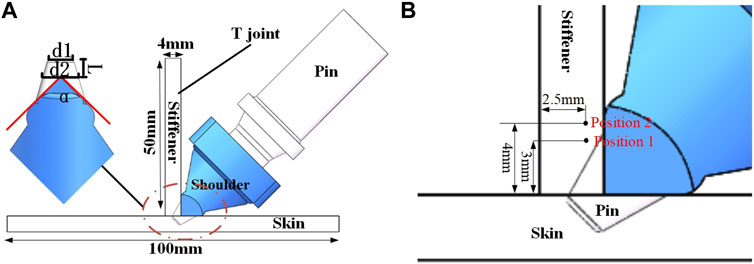
FIGURE 1. CSSFSW mode (A) Dimensions of different components (B) Location for measuring the temperature.
The spindle speed is 2000 rpm, welding speed is 100 mm/min, and the inclination of the pin is 0°. The thermal cycle was measured by using K-type thermocouples. The position (P1 and P2) of the measurement point is 3 and 4 mm away from the skin, and 2.5 mm away from the non-welding side of the stiffener, as shown in Figure 1B. Due to the particularity of CSSFSW, the thermocouple wire and the shoulder interfer when holes are drilled on the front of the plate for temperature measurement. Therefore, the method of grooving on the non-welding surface is adopted, and the thermocouple wires are buried in the groove to avoid interference. A hole is then drilled in the groove to place the thermocouple in it.
Two different tracer metal placement forms are set up to examine the flow behavior of the surface and internal material during the CSSFSW process; 1) Surface material flow: ER5356 wire is placed with a diameter of 1.6 mm at a 90° angle of T-joint. Meanwhile, a process hole with a diameter of 1.8 mm is set at the shoulder to feed the welding wire into the stirring area, as shown in Figure 2A. 2) Internal material flow: A copper foil with a thickness of 0.5 mm and a width of 4 mm is placed at the butt joint of T-joint, as shown in Figure 2B. The flow behavior of metals is analysed by observing the distribution of the preset metals after welding.
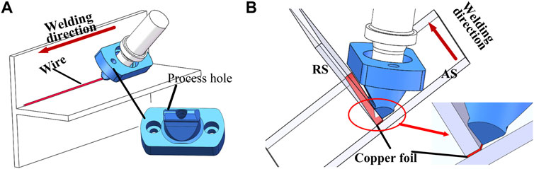
FIGURE 2. Location of the tracer metal (A) Surface-ER5356 welding wire (B) Inside-Copper Foil.
Arbitrary Lagrangian Eulerian (ALE) method was used for the simulation, as shown in Figure 3A. In order to simplify the simulation process, the plunge process was omitted, and a hole was set at the start position, which fully coincide with the pin location.
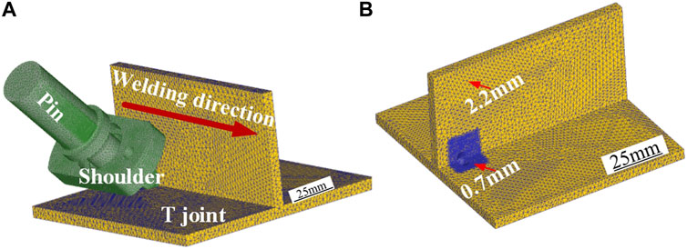
FIGURE 3. Three-dimensional CSSFSW numerical model (A) Meshing diagram (B) T-joint meshing diagram.
The properties of the plate are defined as visco-plastic, and both the pin and shoulder are defined as rigid materials. The workpiece is divided into 150,000 tetrahedral cells with a minimum and maximum size of 0.7 and 2.2 mm, respectively. The number of stirring pin grids is 50,000, and the size variation range is 0.5–1.4 mm. Whereas the number of shoulder grids is 100,000, and the grid size is 0.4–1.2 mm. To improve the accuracy of the calculation, local refinement is performed at the center of the weld along with the adaptive re-meshing, as shown in Figure 3B.
The heat is generated mainly from the friction and plastic deformation during the FSW. The friction heat was produced when the pin made a contact with the plate. According to the previous research (Su et al., 2019), the friction heat (Qfriction) can be calculated by Eq. 1.
where, γis the slip rate, andμand p are the friction coefficient and the pressure, respectively. μis set as 0.46 andγ as 0.33 for the pin, there is no shoulder with the friction tool, so the heat generation by the shoulder is set to 0. The heat generated from the plastic deformation (Qplastic) can be calculated by Eq. 2.
where, βis the heat generation conversion rate due to the plastic deformation, and has been set as 0.9 during the process. σandεare equivalent stress and plastic strain rate, respectively.
The CSSFSW process is a typical thermal-mechanical coupled problem. Therefore, Johnson-Cook (JC) model can be used to describe the large strain, high strain rates and strength limits in high temperature environments of the metal materials, obtained by experiment. JC model can be described as Eq. 3 (Su et al., 2019).
A, B, and n represent the quasi-static tensile yield strength at room temperature, strain hardening coefficient and strain hardening index of the material, respectively. C is the strain rate hardening coefficient, m is the thermal softening index,
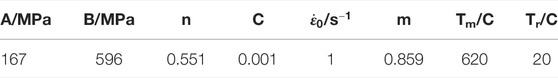
TABLE 2. Parameters of Johnson-Cook constitutive equation for 5,083 aluminum alloy.
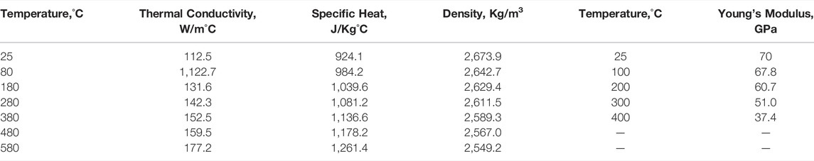
TABLE 3. Thermal properties of 5,083 aluminum at different temprature.
The boundary conditions in the simulation mainly include thermal boundary conditions and displacement boundary conditions. During the CSSFSW process, heat conduction occurs among the workpieces, pin and fixtures. While in other locations, heat convection and heat radiation are the main heat transfer methods. The heat transfer during FSW is a complicated process, and no complete theory has been able to fully explain it. The initial temperature of the pin and the workpiece is set to 20°C. The heat convection coefficient between the workpiece and the pin is 11 N/mm°C, and between the workpiece and the environment is set to 0.02 N/mm °C. The heat convection coefficient is 1 N/mm °C between the bottom workpiece and the environment.
The displacement boundary condition includes the degree of freedom constraints of the pin and the workpiece. The pin is set as a rigid body, and the movement of the stirring tool in welding is simulated by applying the translation and/or rotation of the reference point, and the workpiece degrees of freedom of each boundary speed are limited.
The temperature results obtained from the numerical simulation and the experiment of P1 and P2 are compared to verify the validity of the numerical simulation, as shown in Figure 4. The values obtained by the simulation and the experiment are in line with each other. The maximum temperature of P1 and P2 obtained by the numerical simulation are 431.4 and 375.9°C, and they are 401.1 and 357.8°C obtained through the experiment. The maximum temperature difference does not exceed 7%, showing high accuracy. Therefore, this model can describe T-joint SSFSW process with great satisfaction.
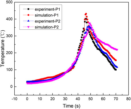
FIGURE 4. Temperature change of the P1 and P2 location during the process.
Figure 5 shows the numerical based surface temperature distribution of T-joint at different time periods. In the initial stage of the traverse, the friction between the pin and the material just start, and the temperature is lower at this time. With the movement of the pin, the pin is in full contact with the material and sufficient friction is generated to increase the temperature. The heat is conducted to the material around the pin and forms an elliptical temperature gradient. Upon further traversing, heat dissipates on the plate, and the area forming temperature gradient is also expanding.
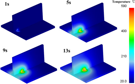
FIGURE 5. Temperature distribution at different time during the process.
Figure 6 displays the temperature distribution on the cross-section of the joint in the stable welding stage. The maximum temperature of the advancing side (AS) and the retreating side (RS) are 575 and 532°C, respectively. Whereas, the temperature on the AS is higher than that on the RS. At the bottom of the pin, the metal temperature is found to be 465°C, where the diameter of the pin is the smallest and the linear velocity is the lowest.
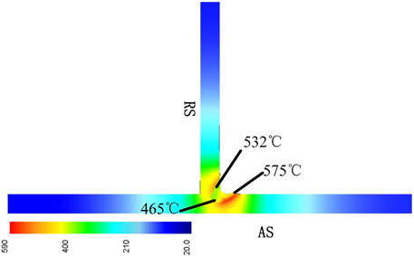
FIGURE 6. Temperature distribution at the joint section.
Figure 7 shows the simulation of the material flow on the surface. The plastic material in front of the pin is softened by the friction heat. When the pin moves in the traverse direction, the rotating pin extrudes the plastic metal and assists the material flow in the traverse direction. The metal on both the AS and the RS flows along the rotational direction of the pin. However, the angle formed by the material flow direction on the forward side and the traverse direction is smaller than that on the backward side. The instantaneous linear velocity along the welding direction on the AS is the sum of the welding speed and the rotational linear speed of the pin. Whereas, the RS velocity are the difference between both of them. Therefore, the shear deformation on the AS is greater than that on the RS. it can be inferred that the rotation of the pin has a greater effect on the plastic metal than the extrusion on the AS. This is the opposite for the case of the RS. Due to the high rotational speed of the pin, the plastic metal flows around it in the direction of rotation.
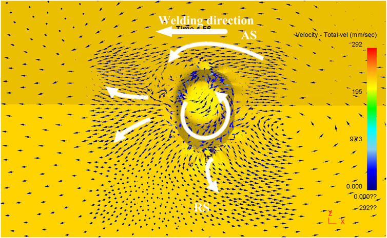
FIGURE 7. Materials flow on the surface.
The distribution of the pre-filled ER5356 wire inside the weld is shown in Figure 8A that can reflect the flow of surface material. Regions five and six are the distribution on the RS and the AS, respectively. The enlarged images are shown in Figure 8B and Figure 8C. The distribution area of the filler metal on the AS is larger than that on the RS, and are 88047 and 201,459 μm2 respectively. Whereas, the maximum distribution widths on both AS and RS are 1,172.25 and 1,687.84 μm. The materials accumulated on the AS, and longer distribution width refers to more vigorous material flow occurring on the AS. It can be visualised that the ER5356 wire is still distributed on the surface of the weld, and the center line of the pre-set metal on the AS and the RS is nearly 45°, which is perpendicular to the insertion direction of the pin.
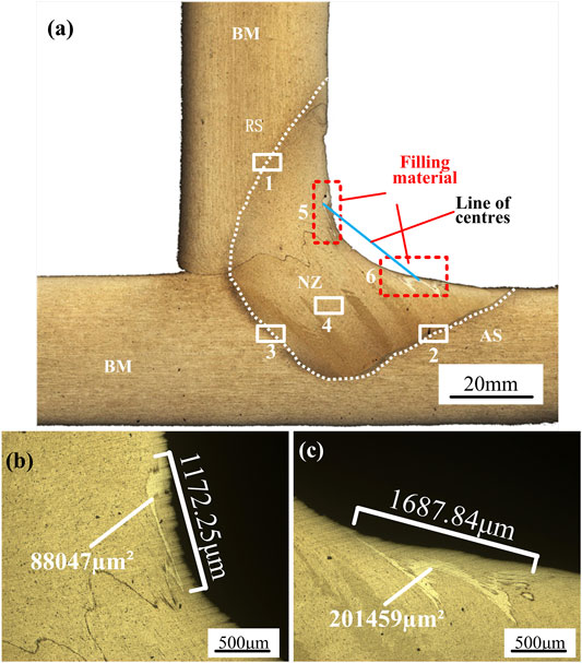
FIGURE 8. ER5356 wire distribution (A) Cross sectional view (B) RS (C) AS.
The simulations of the internal material flow have been carried out in parallel and perpendicular to the welding direction, and are shown in Figures 9A,B respectively. According to the research (Cui et al., 2008; Fonda et al., 2012), the material that located in front of the pin does not flow in the welding direction under the pin extrusion, on the contrary, it is transported backward under the rotation movement, and the material behind the pin is backfilled toward the welding direction, as shown in Figure 9A. Perpendicular to the welding direction, the material moves upward along the pin, and at the top surface, the downward flow trend occurs due to the extrusion of the stationary shoulder, the material near the bottom of the workpiece flows toward the top surface, as shown in Figure 9B.
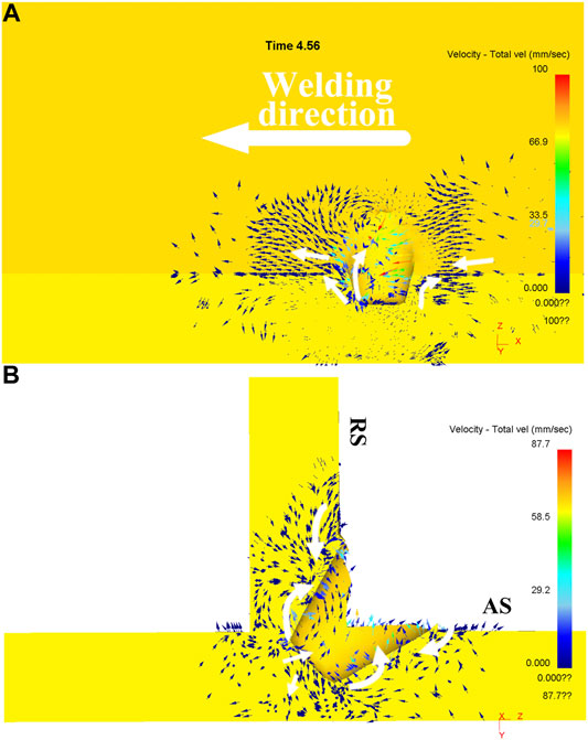
FIGURE 9. Metal flow in the weld (A) Along the welding direction (B) Vertical welding direction.
Figure 10 illustrates the distribution of the pre-set copper foil in the weld, in which the dotted line is the original position of the copper foil. Comparing the initial position of the position after welding, on the RS side, the copper foil transferred to the direction of the weld surface, which is consistent with the simulation. The original copper foil can be divided into four areas (A, B, C and D) along the vertical direction of the pin, The copper foil in the area A is not in the stirring zone, and its shape has not changed. Whereas, in area B, the copper foil was transferred along the pin and was partially broken, but it did not transfer to the inside of the weld. This is because this area is located at the tip of the pin, where the diameter is small and the linear velocity is low. Furthermore, the energy is not enough to drive the material flow along the circumference of the pin. Therefore, it stays in the original position as the pin moves. No copper foil was found in the C area. The reason for this is that the material in the area C was transferred to the area D, whereas the material in the area D was filled to the AS under the high rotational speed of the pin. Thus, a copper strip was then formed within the weld.
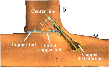
FIGURE 10. Copper foil distribution.
It can be observed that the center line of the copper strip is also about 45°, which is perpendicular to the insertion direction of the pin. This is consistent with the direction of the center line of the preset ER5356 wire distributed in the weld, also shown in Figure 8A. Therefore, it is concluded that the material in the CSSFSW process flows in the same plane in the weld nugget zone due to the absence of the rotation and friction of the shoulder.
The temperature change and material flow behavior during the welding process affect the microstructure of the joint. Figure 11 is an enlarged view of areas 1, 2, 3 and 4 as previously presented in Figure 8A. Area one and Area two are the AS and RS regions, respectively. The boundary between the nugget zone (NZ) and the base metal (BM) on the AS is more noticeable than that on the RS. The main reason is that during the welding process, the material was filled from the RS to the AS. Hence, the material on the AS underwent more severe plastic deformation than on the RS, However, the material on the RS has a longer contact time with the thermo-mechanically affected zone (TMAZ). Since the microstructure changes are relatively gentle, the boundaries are found to be indistinct. Area three and four are the bottom areas of the weld and the NZ, respectively, The material in the NZ has severe plastic deformation and dynamic recrystallization under the high rotational speed of the pin and the welding thermal cycle, the microstructure is fine equiaxed crystal. The grains in the nugget area in the area three are observed as finer than area four. This is because area three is located at the tip of the stirring pin, which is subjected to severe plastic deformation and is less affected by temperature thermal cycling. Due to the low heat input of CSSFSW, the TMAZ and HAZ regions are small. The TMAZ width is between 40–60 μm, and its grains are deformed by the thermo-mechanical action. Whereas, the HAZ is difficult to distinguish.
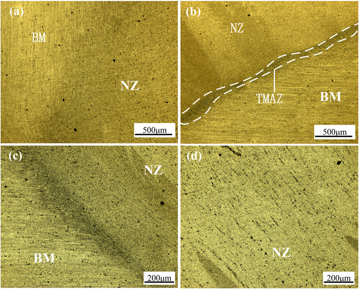
FIGURE 11. Microstructure (A) RS (B) AS (C) Bottom area (D) NZ.
In this study, ALE method is used to study the temperature field and the material flow of 5,083 aluminum alloy T-joint in CSSFSW process, which is verified by experiments. The simulation and experimental results have good agreement. The temperature is distributed in an elliptical shape with a high center and a low periphery. However, the temperature field area is continuously expanded as the welding progresses. The temperature of the AS (575°C) is relatively higher than that of the RS (532°C), and the temperature at the bottom of the pin is lower (465°C) than the AS and RS. The material in front of the pin flows in the welding direction on the surface. Whereas, the material on the AS and the RS flows along the rotation direction of the pin, However, the materials on the RS have an larger angle with the rotation direction. Inside the weld, the material in front of the pin flows backward, and the material behind it fills in the traverse direction. The materials on both sides flow upward along the pin, and eventually flow downward by being squeezed by the stationary shoulder on the surface of the weld. The pre-set material distribution indicates the material flows in the same plane in the nugget zone. The boundary between the NZ and BM on the AS is more obvious than the RS. The NZ microstructure near the tip of the pin is finer than that away from this area, and both the TMAZ and HAZ have a smaller distribution width.
The raw data supporting the conclusion of this article will be made available by the authors, without undue reservation.
All authors listed have made a substantial, direct, and intellectual contribution to the work and approved it for publication.
Financial support for this work was supported by the financial provided by the National Natural Science Foundation of China (51905112), by the Science and Technology Plan Project of Guangzhou City (201807010063), by the Research and Development Project in key areas of Dongguan City (20201200300122), and by the National Key Research and Development Program of China (2020YFE0205300).
The authors declare that the research was conducted in the absence of any commercial or financial relationships that could be construed as a potential conflict of interest.
All claims expressed in this article are solely those of the authors and do not necessarily represent those of their affiliated organizations, or those of the publisher, the editors and the reviewers. Any product that may be evaluated in this article, or claim that may be made by its manufacturer, is not guaranteed or endorsed by the publisher.
The authors are grateful to Wuxi Turbine Blade Co. Ltd. for providing software DEFORM support and assistance by engineer Ji Liu. Thanks to Dr. Jiaqing You and Dr. Zhe Liu for their guidance.
Acerra, F., Buffa, G., Fratini, L., and Troiano, G. (2009). On the Fsw of Aa2024-T4 and Aa7075-T6 T-Joints: An Industrial Case Study. Int. J. Adv. Manuf Technol. 48, 1149–1157. doi:10.1007/S00170-009-2344-9
Ansari, M. A., Samanta, A., Behnagh, R. A., and Ding, H. (2018). An Efficient Coupled Eulerian-Lagrangian Finite Element Model for Friction Stir Processing. Int. J. Adv. Manuf Technol. 101, 1495–1508. doi:10.1007/S00170-018-3000-Z
Chen, D., Zhan, X., Liu, T., Zhao, Y., Qi, N., and Sun, L. (2021). Effect of Porosity Morphology and Elements Characteristics on Mechanical Property in T-Joints during Dual Laser-Beam Bilateral Synchronous Welding of 2060/2099 Al-Li Alloys. Opt. Laser Tech. 140, 107019. doi:10.1016/J.Optlastec.2021.107019
Cui, G. R., Ma, Z. Y., and Li, S. X. (2008). Periodical Plastic Flow Pattern in Friction Stir Processed Al-Mg alloy. Scripta Materialia 58, 1082–1085. doi:10.1016/J.Scriptamat.2008.02.003
Cui, L., Yang, X., Xie, Y., Hou, X., and Song, Y. (2013). Process Parameter Influence on Defects and Tensile Properties of Friction Stir Welded T-Joints on Aa6061-T4 Sheets. Mater. Des. 51, 161–174. doi:10.1016/J.Matdes.2013.04.013
Duong, H. D., Okazaki, M., and Tran, T. H. (2021). Fatigue Behavior of Dissimilar Friction Stir Welded T-Lap Joints between Aa5083 and Aa7075. Int. J. Fatigue 145, 106090. doi:10.1016/J.Ijfatigue.2020.106090
Đurđević, A., Sedmak, A., Živković, A., Đurđević, Đ., Marković, M., and Milčić, M. (2018). Microhardness and Macrostructures of Friction Stir Welded T-Joints. Proced. Struct. Integrity 13, 424–429. doi:10.1016/J.Prostr.2018.12.071
El-Moayed, M. H., Shash, A. Y., Rabou, M. A., and El-Sherbiny, M. G. D. (2021). A Coupled Statistical and Numerical Analysis of the Residual Properties of Aa6063 Friction Stir Welds. J. Adv. Joining Process. 3, 100042. doi:10.1016/J.Jajp.2021.100042
Elwasli, F., Zemzemi, F., Mkaddem, A., Mzali, S., and Mezlini, S. (2015). A 3d Multi-Scratch Test Model for Characterizing Material Removal Regimes in 5083-Al Alloy. Mater. Des. 87, 352–362. doi:10.1016/J.Matdes.2015.07.121
Fonda, R., Reynolds, A., Feng, C. R., Knipling, K., and Rowenhorst, D. (2012). Material Flow in Friction Stir Welds. Metall. Mat Trans. A. 44, 337–344. doi:10.1007/S11661-012-1460-6
Oliveira, P. I., Loureiro, A., Costa, J. M., Ferreira, J., and Borrego, L. (2019). Fatigue Strength Assessment of Misaligned Laser Beam Welded T-Joints by Effective Stress Method. Int. J. Press. Vessels Piping 173, 68–78. doi:10.1016/J.Ijpvp.2019.05.001
Su, Y., Li, W., Patel, V., Vairis, A., and Wang, F. (2019). Formability of an Aa5083 Aluminum Alloy T-Joint Using Ssfsw on Both Corners. Mater. Manufacturing Process. 34, 1737–1744. doi:10.1080/10426914.2019.1669799
Sun, T., Roy, M. J., Strong, D., Simpson, C., Withers, P. J., and Prangnell, P. B. (2019). Weld Zone and Residual Stress Development in Aa7050 Stationary Shoulder Friction Stir T-Joint Weld. J. Mater. Process. Tech. 263, 256–265. doi:10.1016/J.Jmatprotec.2018.08.022
Tian, S., Chen, W., Chen, S., Gu, Y., Gong, X., and Zhan, X. (2020). The Effect of Cryogenic Applications on Tensile Strength of Aluminum 2219-T87 T-Joint Welded by Dual Laser-Beam Bilateral Synchronous Welding. J. Manufacturing Process. 56, 777–785. doi:10.1016/J.Jmapro.2020.05.020
Tisza, M., and Czinege, I. (2018). Comparative Study of the Application of Steels and Aluminium in Lightweight Production of Automotive Parts. Int. J. Lightweight Mater. Manufacture 1, 229–238. doi:10.1016/J.Ijlmm.2018.09.001
Xie, Y., Meng, X., Chang, Y., Mao, D., Yang, Y., Xu, Y., et al. (2022). Ameliorating Strength-Ductility Efficiency of Graphene Nanoplatelet-Reinforced Aluminum Composites via Deformation-Driven Metallurgy. Composites Sci. Tech. 219, 109225. doi:10.1016/J.Compscitech.2021.109225
Xie, Y., Meng, X., Wang, F., Jiang, Y., Ma, X., Wan, L., et al. (2021). Insight on Corrosion Behavior of Friction Stir Welded AA2219/AA2195 Joints in Astronautical Engineering. Corrosion Sci. 192, 109800. doi:10.1016/J.Corsci.2021.109800
You, J., Zhao, Y., Dong, C., Yi, Y., and Su, Y. (2021). Numerical Modeling of Multiphysics Field in Conventional and Stationary Shoulder Friction Stir Welding of Al-Cu Alloy. J. Materi Eng. Perform. 30, 2751–2760. doi:10.1007/S11665-021-05642-2
Zeng, S., Chen, G., Dinaharan, I., Liu, Q., Zhang, S., Sahu, P. K., et al. (2020). Microstructure and Tensile Strength of Aa6082 T-Joints by Corner Stationary Shoulder Friction Stir Welding: Effect of Tool Rotation Speed. J. Materi Eng. Perform. 29, 7094–7103. doi:10.1007/S11665-020-05179-W
Keywords: arbitrary lagrangian eulerian method, stationary shoulder friction stir welding, T-shaped structures, temperature field, material flow
Citation: Wang C, Deng J, Dong C and Zhao Y (2022) Numerical Simulation and Experimental Studies on Stationary Shoulder Friction Stir Welding of Aluminum Alloy T-Joint. Front. Mater. 9:898929. doi: 10.3389/fmats.2022.898929
Received: 18 March 2022; Accepted: 29 March 2022;
Published: 18 May 2022.
Edited by:
Xiangchen Meng, Harbin Institute of Technology, ChinaReviewed by:
H. J. Zhang, Northeastern University, ChinaCopyright © 2022 Wang, Deng, Dong and Zhao. This is an open-access article distributed under the terms of the Creative Commons Attribution License (CC BY). The use, distribution or reproduction in other forums is permitted, provided the original author(s) and the copyright owner(s) are credited and that the original publication in this journal is cited, in accordance with accepted academic practice. No use, distribution or reproduction is permitted which does not comply with these terms.
*Correspondence: Jun Deng, ZGVuZ2pAZ3dpLmdkLmNu; Yunqiang Zhao, emhhb3lxQGd3aS5nZC5jbg==
Disclaimer: All claims expressed in this article are solely those of the authors and do not necessarily represent those of their affiliated organizations, or those of the publisher, the editors and the reviewers. Any product that may be evaluated in this article or claim that may be made by its manufacturer is not guaranteed or endorsed by the publisher.
Research integrity at Frontiers
Learn more about the work of our research integrity team to safeguard the quality of each article we publish.