 Zhu Longji
 Saito Taiki2
- 1Jiangxi Province Key Laboratory of Environmental Geotechnical Engineering and Hazards Control, Jiangxi University of Science and Technology, Ganzhou, China
- 2Research Center for Collaborative Area Risk Management, Department of Architecture and Civil Engineering, Toyohashi University of Technology, Toyohashi, Japan
- 3Earthquake Engineering Research and Test Center of Guangzhou University, Guangzhou, China
- 4Railway Engineering College, Guangzhou Railway Polytechnic, Guangzhou, China
Steel plate concrete composite (SPCC) structure plays an essential role in modular construction, which has been widely applied in the floating foundation vibration reduction system. This study proposed a basis for designing an SPCC floating foundation vibration reduction system with an air spring as the main vibration isolation element. Based on the engineering thermodynamics and aerodynamics theories, the non-linear state equations and dynamic equations of each component of the air spring with auxiliary chamber were established, respectively. According to the operational characteristics of the air spring, the equations were linearized by using the small deviation linearization method under the condition of small amplitude, and the linearized model of the dynamic stiffness of the air spring with an auxiliary chamber was therefore proposed. The reliability of the proposed method was proved by a floating foundation vibration test, which was performed in a solid-state quantum laboratory. The constitutive equations of an air spring model and an SPCC floating foundation model were incorporated into the STERA_3D software. The simulation results showed good agreement with the low-frequency micro-vibration region test data.
Introduction
Composite materials are widely used in new structures (Yang, et al., 2021; Yang, et al., 2022), Steel plate concrete composite (SPPC) is used in floating foundation vibration reduction systems with air spring as vibration isolation element because of its high strength and integrity, microelectronics manufacturing, precision measurement laboratories, and high-speed railway trains owing to their excellent vibration isolation performance. Examples of the application of air springs with auxiliary chambers include ultra-low vibration scanning tunneling microscopy (STM) at the Laboratory of Peter Grünberg Institute (Voigtlander, et al., 2017), National Institute of Standards, and Technology Center for Neutron Research (Soueid et al., 2005), Japanese Shinkansen high-speed trains (Sugahara, et al., 2009), and China Harmony electric multiple units (EMU) (Fan, 2009).
The structure of an air spring with an auxiliary chamber is divided into three parts: the main chamber, throttle orifice, and auxiliary chamber. A simplified schematic of an air spring is shown in Figure 1.
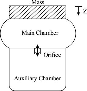
FIGURE 1. Schematic of an air spring with an auxiliary chamber.
In an air spring with an auxiliary chamber, changes in the volume of the main chamber depend on the mass of the spring and external excitation. This change is described by the effective area and the change in the effective area. A throttle orifice connects the main chamber and auxiliary chamber and can be in the form of a hole in the auxiliary chamber or a pipe connecting the two chambers. Its primary function is to provide a damping effect when the main chamber and auxiliary chamber exchange air through the orifice under external excitation. It should be noted that if the air spring vibrates only horizontally and the volume of the main chamber does not change, damping is typically caused by the rubber deformation of the main chamber rather than the orifice. The volume of the auxiliary chamber generally does not change, and the air pressure in this chamber can be controlled using a valve system. In the numerical modeling of an air spring, scholars establish models according to the characteristics of different components of the air spring and then use a dynamic equation to connect the components (Arif, et al., 1993; Eickhoff, et al., 1995; Quaglia and Sorli, 1999; Presthus, 2002; Mazzola, et al., 2014).
Two aspects should be considered in modeling an air spring main chamber (rubber airbag): the stiffness caused by the air pressure in the airbag, and the other is the stiffness and damping caused by rubber deformation. Berg (Berg, 1997; Berg, 1998) and Sanliturk et al. (Sanliturk, et al., 1997) established a non-linear model of an air spring rubber airbag. This model was composed of a linear elastic model, friction model, and Maxwell model in parallel, but the model demonstrated significant errors in characterizing the frequency characteristics of rubber airbags. Moon et al. (Moon, et al., 2010) highlighted that rubber airbags have strong non-linearity in terms of frequency characterization. Therefore, the frequency characteristics of rubber airbags are characterized using the four-parameter fractional derivative Zener model. Fongue et al. (Fongue, et al., 2013) modeled a rubber airbag for vehicle air suspension. Their rubber airbag model used an exponential function (Berg, 1999) to describe the amplitude correlation and hysteresis characteristics of the airbag. The generalized Maxwell model was used to describe the frequency correlation of the rubber airbag.
Two aspects should be considered while modeling the orifice; one part is the stiffness of the high-speed airflow caused by the air pressure difference between the two air chambers while air passing through the orifice, and the other part is the friction damping and inertia damping of air in the orifice. Suda and Kumaki (Suda, et al., 1998) conducted a preliminary study on air springs for railway trains and pointed out that the airflow in the orifice flows at a high frequency between the two air chambers, the air resistance effect increases. Bideaux et al. (Bideaux, et al., 2003) studied airflow characteristics through the orifice and drew the same conclusion as Suda. In addition, Docquier and Paul (Docquier et al., 2007) presented four modeling methods (INTEC GmbH, 2005; ISO 6358:1989, 1989) for throttling devices and gave the frequency range applicable to the four models.
It can be concluded from the aforementioned literature that the air spring model is related to the frequency and amplitude of the excitation. In an experimental study on the semi-automobile air suspension system, Zargar (Zargar, 2007) pointed out that damping in the air spring will increase non-linearly as the natural frequency of the system increases, especially in the 4–6 Hz region. Suda and Kumaki (Suda, et al., 1998) established an air spring suspension system model using A’GEM software and concluded similarly to that of Zargar. To investigate the air suspension of high-speed trains, Docquier et al. (Docquier, et al., 2008) compared and analyzed five air spring models and presented the air spring models that would be suitable below 8 Hz and above 8 Hz. Porumamilla et al. (Porumamilla, et al., 2008) further studied the characteristics of the displacement transmission rate of air springs, pointing out the variable frequency damping characteristics of air springs and highlighting that the natural frequency changes with the opening of the orifice.
The previous studies focused on air springs in the suspension systems of luxury cars and high-speed trains (Alonso, et al., 2010). Both the frequency and the amplitude of the excitation of such systems are large (up to 10 Hz and more than 20 mm). The characterization error for air springs in the case of low-frequency micro-vibrations is relatively large. The requirements for micro-vibration isolation have become more stringent with the development and use of large-scale ultraprecision instruments. Air springs are widely used in low-frequency micro-vibration isolation systems for precision instruments because of their ultralow stiffness. If the change in air spring stiffness with frequency is neglected, the vibration results obtained via simulations and actual measurements become considerably different (Presthus, 2002). Hence, it is essential to consider the change in air spring stiffness with frequency to accurately simulate the mechanical behavior of vibration isolation systems and guide the design of these systems, especially in the low-frequency micro-vibration region.
In this study, the frequency-dependent stiffness of an air spring was derived using the small deviation linearization method and a non-linear damping air spring model. An air spring submodule using C++ was implemented in the STERA_3D (Earthquake Disaster Engineering Research Laboratory, 2020) software to analyze the dynamic performance of the SPCC floating foundation. The reliability of the small deviation linearization method was verified by a floating foundation vibration test, which was performed in a solid-state quantum laboratory. Moreover, the acceleration time histories and the Fourier amplitude of an SPCC floating foundation vibration reduction system were obtained via simulations and vibration tests, which exhibited good agreement. The results also revealed that the proposed air spring model performed well in the low-frequency micro-vibration region.
Mathematical Model of the Air Spring
In this section, each air spring element is assumed to be independent in the mathematical model. The material isotropic and the internal air satisfies the thermodynamic properties under an ideal state. Then, the momentum conservation of the mass on the spring, the gas volume equation of the main and auxiliary chambers, the mass flow equation of the orifice, and the mass continuity equation of the orifice are derived. Finally, the mathematical model is simplified into series and parallel linear springs/linear or non-linear damping elements.
Model of the Air Spring
The main chamber of an air spring is in direct contact with the mass of the spring. The first step of modeling the air spring is to establish the dynamic balance among the inertial force of the mass on the spring, the main chamber pressure, and atmospheric pressure (Shimozawa& Tohtake, 2008), which can be expressed as:
The air pressure in the main chamber is controlled by the airflow through the orifice and the volume change in the main chamber. This pressure can be expressed as:
Considering the safety of the vibration reduction system in real applications, it is better to keep the initial static pressure as low as possible. By limiting the dynamic pressure to be less than 0.8 MPa, effective pressure control should be achieved on eccentric SPCC floating foundations. Since the volume of the auxiliary chamber is constant, the air pressure in the auxiliary chamber can be expressed as:
Damping of the air spring during vertical vibration is achieved by obstructing the airflow in the orifice. The mechanical characteristics of the damping are a combination of viscous damping, and quadratic damping, the airflow through the orifice can be therefore expressed as:
Substituting Eqs 2, 3 into Eqs 1, 4 gives:
Let y denotes the damper displacement, λ and q can be rewritten as:
where,
where,
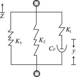
FIGURE 2. Mathematical model of air spring with an auxiliary chamber.
Frequency-Dependent Stiffness of the Air Spring
It is known that a non-linear function can be expanded into a Taylor series around the operating point (Corliss and Chang, 1982). When the deviation range around the operating point is considerably small, the high-order terms of the series can be neglected to obtain a linearized equation containing only the first-order term. This method is referred to as the small deviation linearization method.
We have proposed an SPCC floating foundation vibration reduction system for vibration reduction in large precision instruments, where air springs are the main vibration isolation elements. Precision instruments are susceptible to vibrations, and even micro-vibrations strongly affect their accuracy (Voigtlander, et al., 2017). When the SPCC floating foundation vibration reduction system is in its operating state, micro-vibrations of the air springs occur close to its equilibrium position, that is, the relationship between the stiffness and frequency of an air spring can be determined by using the small deviation linearization method. Therefore, the air spring reaction force, main air chamber pressure, and auxiliary chamber pressure, given by Eqs 1, 2, and 3 are linearized as follows:
The linearization of the orifice airflow was performed earlier by Rongsheng (Rongsheng, 1992), in which the orifice flow resistance coefficient, R, was replaced by βRβ to obtain
The time derivatives of Eqs 10, 11 are given by
where,
The Laplace transform of Eq. 17 is given by
As force and displacement always have opposite signs, we obtain
As stiffness is positive, we obtain
Vertical Vibration Test of the Air Spring
Experimental Equipment
Figure 3 shows the illustration of the experimental equipment. It is seen that the upper end of the table was fixed, and the lower end performed simple harmonic motion at different frequencies. The main and auxiliary chambers were connected by the orifice. The experimental system works under the conditions of constant pressure. The auxiliary chamber and an air compressor were connected by a connecting pipe. An air compressor provided stable air pressure during the test. The top of the spring was fixed, and the bottom of the spring was connected to the vibration test table, which generated sinusoidal excitation. Therefore, the deformation of the spring was sinusoidal vibration with a fixed amplitude. As the experimental parameters were known, the measured dynamic load was a sinusoidal periodic signal. The laser sensor and load cell were used to measure the spring displacement and dynamic load signals. The dynamic stiffness of the air spring was obtained by dividing the minimum dynamic load by the minimum spring displacement.
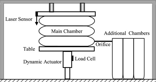
FIGURE 3. Illustration of experimental equipment.
Parameters of the Air Spring
The air spring with an auxiliary chamber used in the SPCC floating foundation vibration reduction system of an electron beam exposure machine was utilized in the test performed in a solid-state quantum laboratory. The frequencies of the air spring were 0.1, 0.5, 0.8, 1, and 2 Hz, and its displacement was ±1, ±2.5, ±5, ±10, ±15, and ±20 mm. The physical parameters of the air spring are shown in Table 1.
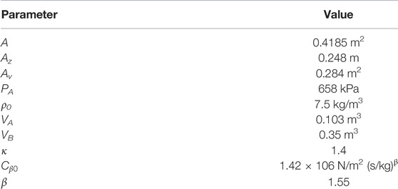
TABLE 1. Physical parameters of the air spring.
Verification of Frequency-Dependent Stiffness
Figure 4 shows the time histories of the measured air spring displacement and dynamic load (i.e., the dynamic pressure of the spring). The frequency-dependent stiffness is prepared as shown in Table 2 and Figure 5. It can be observed that the maximum calculated and experimental values were 1,137 kN/m and 1,149 kN/m (corresponding error was 1.0%), respectively, when the excitation frequency was 0.1 Hz, and the excitation amplitude was 1 mm. The minimum calculated and experimental values were 1,005 kN/m and 943 kN/m (corresponding error was 6.2%), respectively, when the excitation frequency was 2.0 Hz, and the excitation amplitude was 5 mm. The error was 0.07%, which is the smallest one when the excitation amplitude was 1 mm and the frequency was 1.0 Hz. It is noted that the stiffness of the air spring decreases with the increment of the excitation amplitude.
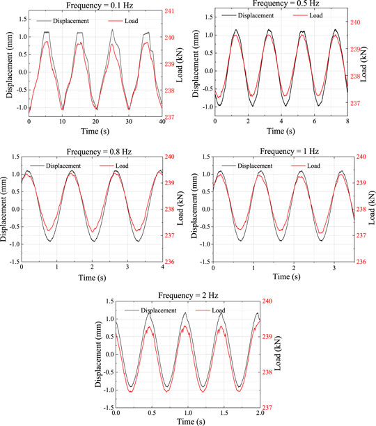
FIGURE 4. Experimentally measured time-dependent displacement and load (the displacement in ±1 mm).

TABLE 2. Experimental value of frequency-dependent vertical stiffness of air spring.
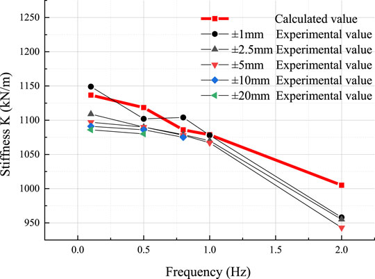
FIGURE 5. Comparison between experimentally measured and calculated frequency-dependent stiffness.
It is seen that in the low-frequency range (below 1 Hz), the error is less than 6.0%, which indicates that Eq. 20 can be used to accurately evaluate the frequency-dependent stiffness of the air spring. The stiffness of the air spring has a high degree of non-linearity, which is in good agreement with the experimental results in the low-frequency range but not so in the high-frequency range. This is because the value of β in Eq. 20 has considerable influence in the high-frequency range. Hence, the value of β can be modified appropriately using the experimental results.
Vibration Test of the Steel Plate Concrete Composite Floating Foundation Reduction System
Steel Plate Concrete Composite Floating Foundation Vibration Reduction System
An SPCC floating foundation was built in the underground space in the laboratory, as shown in Figure 6. Air spring isolators were installed between the SPCC floating foundation and underground. Then the precision instruments were placed on the SPCC floating foundation. The plane size of the SPCC floating foundation was determined according to laboratory conditions and the resonant frequency of the structure of the precision instruments.
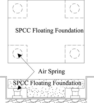
FIGURE 6. SPCC Floating foundation vibration reduction system.
Test Parameter Setup
The parameters of the air spring used in the vibration test of the SPCC floating foundation vibration reduction system are the same as that of the air spring used in the vertical vibration experiment. The physical parameters of the SPCC floating foundation vibration reduction system are listed in Table 3. The vibration test measurement scheme of the SPCC floating foundation vibration reduction system is shown in Figure 7.
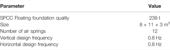
TABLE 3. Physical parameters.
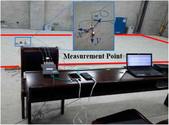
FIGURE 7. Vibration test measurement scheme of the SPCC floating foundation vibration reduction system. (Redline is the outline of the SPCC floating foundation).
Comparison of the Simulation and Test Results
Figures 8, 9 show the acceleration time histories and power spectral density of the system, respectively, which were obtained via simulations and physical testing. It can be observed that the response of the SPCC floating foundation simulated by the proposed air spring model in this study is accurate in terms of the acceleration and the Fourier amplitude of frequency distribution. The simulation error of peak acceleration is in the range of 4.07%–9.41%, as shown in Figure 10. Considering the small magnitude of micro-vibration (micron level) and noise interference, such an error is acceptable. The simulation results agree well with the experimental data in the main frequency (approximately 1 Hz) of the SPCC floating foundation vibration reduction system, and the second frequency (approximately 5 Hz) also has a certain degree of accuracy. To sum up, the model proposed in this study performs well in the low-frequency micro-vibration region, especially for micro-vibrations whose frequency is less than 6 Hz.
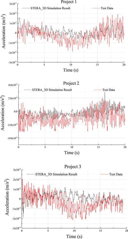
FIGURE 8. Comparison of acceleration time histories for the SPCC floating foundation vibration reduction system obtained via simulations and testing.
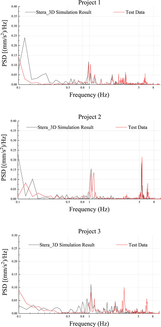
FIGURE 9. Comparison of Fourier amplitude spectra for the SPCC floating foundation vibration reduction system obtained via simulations and testing.

FIGURE 10. Comparison of peak acceleration for the SPCC floating foundation vibration.
Conclusion
In this study, the frequency-dependent stiffness model for air spring with non-linear damping was proposed using the small deviation linearization method. The reliability of the method was verified by the vertical vibration test of the air spring and the SPCC floating foundation. It can conclude that the frequency-dependent stiffness model for air spring with non-linear damping proposed in this study is highly consistent with the experimental data, revealing its correctness and accuracy. The proposed air spring model is suitable for simulating the micro-vibration of the SPCC floating foundation in the low-frequency region, especially in the case of frequency being less than 6 Hz.
Data Availability Statement
The original contributions presented in the study are included in the article/Supplementary Material, further inquiries can be directed to the corresponding author.
Author Contributions
Conceptualization, ZL and ST; methodology, ZL; software, WH; validation, ZL and WH; data curation, ZL.; writing—original draft preparation, ZL, ST, and ZZ; writing—review and editing. All authors have read and agreed to the published version of the manuscript.
Conflict of Interest
The authors declare that the research was conducted in the absence of any commercial or financial relationships that could be construed as a potential conflict of interest.
Publisher’s Note
All claims expressed in this article are solely those of the authors and do not necessarily represent those of their affiliated organizations, or those of the publisher, the editors and the reviewers. Any product that may be evaluated in this article, or claim that may be made by its manufacturer, is not guaranteed or endorsed by the publisher.
References
Alonso, A, Gimenez, JG, Nieto, J, and Vinolas, J (2010). Air Suspension Characterisation and Effectiveness of a Variable Area Orifice. Veh. Syst. Dyn. 48 (S1), 271–286. doi:10.1080/00423111003731258
Arif, M., Dewey, M. S., Greene, G. L., and Snow, W. M. (1993). Facilities for Fundamental Neutron Physics Research at the NIST Cold Neutron Research Facility. J. Res. Natl. Inst. Stan. 98, 135–144. doi:10.6028/jres.098.010
Berg, M. (1997). A Model for Rubber Springs in the Dynamic Analysis of Rail Vehicles. Proc. Institution Mech. Eng. Part F J. Rail Rapid Transit 211 (2), 95–108. doi:10.1243/0954409971530941
Berg, M. (1999). A Three-Dimensional Airspring Model with Friction and Orifice Damping. Veh. Syst. Dyn. 33 (Suppl. 1), 528–539. doi:10.1080/00423114.1999.12063109
Berg, M. (1998). A Nonlinear Rubber Spring Model for Rail Vehicle Dynamics Analysis. Veh. Syst. Dyn. 30 (3-4), 197–212. doi:10.1080/00423119808969447
Bideaux, E., Champagne, J. Y., and Scavarda, S. (2003). Pneumatic Orifices Characterization Using a Computational Fluid Dynamics Approach, Proceedings of the Fourth International Symposium on Fluid Power Transmission and Control. Chine: WUHAN.
Corliss, G., and Chang, Y. F. (1982). Solving Ordinary Differential Equations Using Taylor Series. ACM Trans. Math. Softw. 8 (2), 114–144. doi:10.1145/355993.355995
Docquier, N., Fisette, P., and Jeanmart, H. (2008). Model-based Evaluation of Railway Pneumatic Suspensions. Veh. Syst. Dyn. 46, 481–493. doi:10.1080/00423110801993110
Docquier, N., Fisette, P., and Jeanmart, H. (2007). Multiphysic Modelling of Railway Vehicles Equipped with Pneumatic Suspensions. Nvsd 45 (6), 505–524. doi:10.1080/00423110601050848
Earthquake Disaster Engineering Research Laboratory (2020). Earthquake Disaster Engineering Research Laboratory. Toyohashi: Toyohashi University of Technology. Available at: http://www.rc.ace.tut.ac.jp.
Eickhoff, B. M., Evans, J. R., and Minnis, A. J. (1995). A Review of Modelling Methods for Railway Vehicle Suspension Components. Veh. Syst. Dyn. 24 (6-7), 469–496. doi:10.1080/00423119508969105
Fan, L. (2009). Comfort Simulation and Analysis of High-Speed EMU. Dalian: Dalian Jiaotong University.
Fongue, W. A. (2013). Air Spring Air Damper: Modelling and Dynamic Performance in Case of Small Excitations. SAE Int. J. Passeng. Cars - Mech. Syst. 6, 1196–1208. doi:10.4271/2013-01-1922
ISO 6358:1989 (1989). Pneumatic fluid power - Components using compressible fluids - Determination of flow-rate characteristics. ISO.
Mazzola, L., and Berg, M. (2014). Secondary Suspension of Railway Vehicles - Air Spring Modelling: Performance and Critical Issues. Proc. Institution Mech. Eng. Part F J. Rail Rapid Transit 228 (3), 225–241. doi:10.1177/0954409712470641
Moon, J.-H., and Lee, B.-G. (2010). Modeling and Sensitivity Analysis of a Pneumatic Vibration Isolation System with Two Air Chambers. Mech. Mach. Theory 45 (12), 1828–1850. doi:10.1016/j.mechmachtheory.2010.08.006
Oda, N., and Nishimura, S. (1970). Vibration of Air Suspension Bogies and Their Design. Bull. JSME 1355, 43–50. doi:10.1299/jsme1958.13.43
Porumamilla, H., Kelkar, A. G., and Vogel, J. M. (2008). Modeling and Verification of an Innovative Active Pneumatic Vibration Isolation System. J. Dyn. Syst. Meas. control 130, 3. doi:10.1115/1.2807049
Presthus, M. (2002). Derivation of Air Spring Module Parameters for Train Simulation. Lulea: Department of Applied Physics and Mechanical Engineering.
Quaglia, G., and Sorli, M. (1999). Analysis of Vehicular Air Suspensions. Proceedings of the Fourth JHPS International Symposium on Fluid Power, 15 - 17 November, 1999, Tokyo. doi:10.5739/isfp.1999.389
Rongsheng, G. (1992). Vibration Characteristics and Parameter Calculation of Air Spring Suspension. Railw. Veh. 5, 1–6.
Sanliturk, K. Y., Imregun, M., and Ewins, D. J. (1997). Harmonic Balance Vibration Analysis of Turbine Blades with Friction Dampers, New York: Journal of Vibration and Acoustics, 96–103. doi:10.1115/1.2889693
ShimozawaTohtake, K. T., and Tohtake, T. (2008). An Air Spring Model with Non-linear Damping for Vertical Motion. QR RTRI 49, 209–214. doi:10.2219/rtriqr.49.209
Soueid, A., Amick, H., and Zsirai, T. (2005). Addressing the Environmental Challenges of the NIST Advanced Measurement Laboratory. Proceedings of the SPIE - The International Society for Optical Engineering 5933, 18 August 2005, San Diego, California, United States; doi:10.1117/12.618915
Suda, Y., and Seiichiro, K. (1998). Study on Curving Characteristic of Vehicles with Nonlinear Air Suspension (Special Issue on Nonlinear Dynamics) JSME. Mach. Elem. Manuf. 41 (3), 668–673. doi:10.1299/jsmec.41.668
Sugahara, Y., Kazato, A., Koganei, R., Sampei, M., and Nakaura, S. (2009). Suppression of Vertical Bending and Rigid-Body-Mode Vibration in Railway Vehicle Car Body by Primary and Secondary Suspension Control: Results of Simulations and Running Tests Using Shinkansen Vehicle. Proc. Institution Mech. Eng. Part F J. Rail Rapid Transit 223, 517–531. doi:10.1243/09544097JRRT265
Voigtländer, B., Coenen, P., Cherepanov, V., Borgens, P., Duden, T., and Tautz, F. S. (2017). Low Vibration Laboratory with a Single-Stage Vibration Isolation for Microscopy Applications. Rev. Sci. Instrum. 88, 023703. doi:10.1063/1.4975832
Yang, Z., Safaei, B., Sahmani, S., and Zhang, Y. (2022). A Couple-Stress-Based Moving Kriging Meshfree Shell Model for Axial Postbuckling Analysis of Random Checkerboard Composite Cylindrical Microshells. Thin-Walled Struct. 170, 108631. doi:10.1016/j.tws.2021.108631
Yang, Z., Zhao, S., Yang, J., Lv, J., Liu, A., and Fu, J. (2021). In-plane and Out-Of-Plane Free Vibrations of Functionally Graded Composite Arches with Graphene Reinforcements. Mech. Adv. Mater. Struct. 28 (19), 2046–2056. doi:10.1080/15376494.2020.1716420
Zargar, B (2007). Model Development, Validation and Nonlinear Control of Pneumatic Suspensions. Diss. University of Ottawa. Canada. doi:10.20381/ruor-12109
Nomenclature
A Effective area of the main chamber at static height
Az Change in effective area, dA/dz
Av Rate of change of diaphragm volume
Cd Flow coefficient
d Diameter of orifice
κ Polytropic index
PA Pressure in the main chamber
PB Pressure in the auxiliary chamber
Pat Atmospheric pressure
P0 Internal pressure in air spring at static height (z = 0)
ρ0 Initial density of air
q Airflow through the orifice
Rβ Resistance coefficient
S0 Area of orifice
VA Initial main chamber volume
VB Initial auxiliary chamber volume
z Vertical displacement of air spring from the static height
β Damping coefficient
Superscript ¯ derivative of vertical displacement
Superscript ˙ derivative of time
Subscript L Laplace transform
Keywords: air spring, low frequency, micro-vibration, frequency-dependent stiffness, SPCC floating foundation, vibration isolation, ultraprecision instruments
Citation: Longji Z, Taiki S, Heisha W and Zilin Z (2022) Investigation on Low-Frequency Micro-Vibration Model of Air Spring With Auxiliary Chamber for Steel Plate Concrete Composite Structures. Front. Mater. 9:896497. doi: 10.3389/fmats.2022.896497
Received: 15 March 2022; Accepted: 19 April 2022;
Published: 10 May 2022.
Edited by:
Zhicheng Yang, Zhongkai University of Agriculture and Engineering, ChinaCopyright © 2022 Longji, Taiki, Heisha and Zilin. This is an open-access article distributed under the terms of the Creative Commons Attribution License (CC BY). The use, distribution or reproduction in other forums is permitted, provided the original author(s) and the copyright owner(s) are credited and that the original publication in this journal is cited, in accordance with accepted academic practice. No use, distribution or reproduction is permitted which does not comply with these terms.
*Correspondence: Wenliuhan Heisha, MTExMTcxNjAxM0BlLmd6aHUuZWR1LmNu