 Chunzhi Wang
 Changbo Lu1
94% of researchers rate our articles as excellent or good
Learn more about the work of our research integrity team to safeguard the quality of each article we publish.
Find out more
ORIGINAL RESEARCH article
Front. Mater., 31 August 2022
Sec. Mechanics of Materials
Volume 9 - 2022 | https://doi.org/10.3389/fmats.2022.886150
In this study, the stress, strain, and flow blocking effect of the explosion-proof honeycomb structure of a UAV fuel tank are analyzed when it is impacted by continuous fluid caused by explosion, and the main stress concentration areas and overall stress distribution are analyzed. It simplifies the problem due to the symmetry of the barrier and explosion-proof structure of the UAV fuel tank. Taking a three-layer superposition model of the UAV fuel tank as the research object, the stress and strain of the material structure under detonation impact are analyzed by a bidirectional fluid structure coupling method. The simulation results of choke flow of the fuel tank structure are obtained, which provides reference for the structural optimization design of the honeycomb barrier and explosion-proof material for the UAV.
Explosion-proof material is a kind of functional material which is filled in flammable and explosive gas or liquid containers to prevent the gas or liquid from exploding. At present, metal foam materials, metal honeycomb mesh materials, and organic compound foam materials are widely used as explosion-proof materials (Han et al., 2011). Explosion-proof materials adopt barrier and explosion-proof technology and equipment to isolate the burning or explosion flame so that it cannot spread to other equipment through pipelines.
The geometrical structure and internal structure section of a UAV fuel tank are shown in Figure 1. The UAV fuel tank is a rectangular geometric structure with a length of 700 mm, a width of 200 mm, and a height of 100 mm.
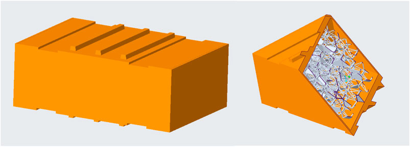
FIGURE 1. Diagram of the full geometry of the UAV fuel tank and its interior section.
The UAV fuel tank barrier explosion-proof material is an important material used to fill the fuel and oil tanks of weapons and equipment to prevent the tank from being killed and exploded in the event of accidental damage such as a direct fire strike or impact. It divides the inner cavity of the container into many “small single cavities” as shown in Figure 2. When flammable and explosive gases encounter open fire, the flame is torn into countless small “flame clusters” when it passes through the honeycomb explosion-proof material. The front of the flame is in a discontinuous state, and the energy (thermal energy and kinetic energy) of the flame will be absorbed by the explosion-proof materials. Under the action of large Rayleigh motion, the flame gradually loses its thermal balance and cannot maintain combustion and propagation, resulting in the extinction of the whole flame front, which plays a role in curbing the propagation of the flame, thus causing the attenuation of the shock wave generated by combustion or explosion.
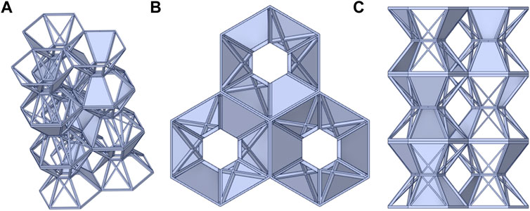
FIGURE 2. Structure model view of the barrier and explosion-proof material of the UAV fuel tank. (A) Isoaxonometric. (B) Top view. (C) Side view (right and front).
In practical application, a certain amount of hexagonal barrier and explosion-proof materials is usually filled into containers (fuel tanks, oil tanks, etc.), as shown in Figure 2. It can be seen from the figure that the location and direction of the barrier and explosion-proof materials after loading are random and have no regularity, and there is no specific cavity formed by the combination of multiple spherical materials. Based on this, it can be judged that the spherical barrier and explosion-proof effect do not depend on the combination of materials, so the impact resistance of the whole oil tank and barrier and explosion-proof materials can be simplified as the impact resistance of a single spherical barrier and explosion-proof material. For a specific single model, three different explosion locations are selected, and the equivalent charge is unified to 50 g according to the requirements. The specific working conditions are introduced later.
In the field of numerical simulation, the finite element method and finite difference method are still the main numerical analysis methods for calculating explosion impact problems. The current finite element software programs have Lagrange and fluid-structure coupling algorithms (Bungartz, 2006).
The Lagrange method is mostly used to solve solid mechanics problems. The Lagrange method uses the Lagrange element to describe explosive materials and structures at the same time (Chen and Kim, 2009; Zhou et al., 2009). The interaction between explosive materials and structures is realized by defining the contact relationship or adopting a common grid. The advantage of the Lagrange method is that the nodes and elements move together with the deformation of materials, and its grid also deforms with the deformation of structures, so the deformation of various material interfaces and free interfaces in the computational domain can be clearly observed. The Lagrange method has great advantages in solving small deformation problems of solid materials. For the analysis of flow-through coupling problems and large deformation problems of solids, the computer calculation is often terminated due to the excessive distortion of the grid, which leads to the reduction of analysis accuracy and even the generation of negative volume.
When solving the fluid–solid coupling problem, some scholars put forward the method of coupling Euler–Lagrange, that is, the arbitrary Lagrange–Euler method, which has the advantages of the Lagrange method and Euler equation method in computational fluid dynamics (ANSYS, Inc, 2009; Paolo, 2010; Liu and Lin, 2008; Lucy, 1977; Monaghan, 1988; Rabczuk et al., 2006). They are organically combined to form a hybrid technology, called the ALE method for short.
In this study, the ALE algorithm is used to realize the explosion process by using a fluid structure coupling algorithm. First, the Euler algorithm is used for explosives and other fluid materials, and the Lagrange algorithm is used for other structures, and then the interaction is processed by the fluid structure coupling command. The advantage of this method is that the mesh points can move with the material at the same time and can also be fixed in space. Even the mesh nodes can be fixed in one direction and move with the object in the other direction. ALE’s computational grid can move in any form in space, which overcomes the problem of numerical calculations of large deformation of solids. When analyzing fluid–solid coupling problems, the ALE method can easily establish complex models and can establish fluid and solid, respectively. At present, this method has become an important numerical analysis method for analyzing large strain problems.
The ALE method in LS-DYNA is used to describe the fluid unit, and the fluid structure coupling calculation is carried out with the structure described by the Lagrange method to simulate the failure process of the UAV fuel tank structure during explosion.
Its advantage lies in ensuring energy conservation and computational stability in the contact process. In the process of an explosion, when the fluid comes in contact with the structure, the fluid is generally regarded as the main substance and the structure as the slave substance. In each calculation step, it is first checked whether each slave node penetrates the main material surface, and if it does not penetrate, it would not do any treatment to the slave node, which ensures the calculation stability and takes into account the calculation speed. As a result, it greatly saves calculation time.
Fluid flow follows the basic physical conservation laws, including the conservation of mass, momentum, and energy. The governing equations of the law of conservation of mass and momentum of general compressible Newtonian fluids are described as follows.
where,
The conservation equation of the structural part is derived from Newton’s second law.Here,
In the equation,
Based on the aforementioned fluid structure coupling method, the alternate solution method is used to solve the fluid structure coupling problem by the LS-DYNA simulation solver. The alternate solution method divides the fluid and structure into two separate solution domains, alternately solves these two domains at each time in the numerical solution process, and transfers relevant physical quantities through the coupling interface. The nodal velocity on the coupling interface is transferred to the fluid as the velocity boundary condition of the fluid region, and the ALE method is used to solve the fluid region independently. The nodal forces on the coupling interface are transferred to the structure as the force boundary conditions in the solid domain, and the dynamic equations are solved separately by the traditional method.
The whole problem is divided and coupled by engineering analysis software ansys/lsdyna, and the bidirectional coupling of Euler and Lagrange can be completed for the finite element model in the software. The specific keywords of fluid structure coupling are set as shown in Figure 3.
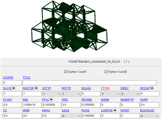
FIGURE 3. Finite element model of the fluid structure interaction interface and fluid structure coupling keyword card
The specific numerical simulation conditions are as follows. The shock tube with a size matching the fuel tank structure of the UAV is also set as a rigid wall, and the charge size is 1.6 cm spherical charge. The explosion process of the charge in the shock tube is numerically simulated by ANSYS/LS-DYNA finite element software, and the initiation process of 50 g spherical charge is simulated by multi-material arbitrary Lagrangian–Eulerian method provided by LS-DYNA. Because the structure ball is complex and symmetrical, the full model numerical simulation is adopted to display the shell transparently. The charge is located in the center of the shock tube, 2 cm away from the UAV fuel tank structure, as shown in Figure 4:
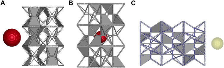
FIGURE 4. Explosion model of different explosion locations of the UAV fuel tank structure. (A) Explosion location point 1. (B) Explosion location point 2. (C) Explosion location point 3.
Because of the asymmetric model of the complex structure, it is impossible to consider simplified symmetry. The non-reflective wall around the model is used to simulate the response of a filled explosion-proof structure under explosion, as shown in Figure 5.
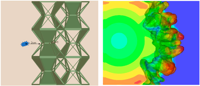
FIGURE 5. Boundary setup and explosion spreading process.
The large-scale general finite element software LS-DYNA used in this study contains a mature ALE algorithm function. The fluid structure coupling algorithm is used to realize the explosion process. The Euler algorithm is used for explosive and other fluid materials, and the Lagrange algorithm is used for other structures, and then the interaction is processed by the fluid structure coupling command. The advantage of this method is that the grid points can move with the material at the same time, and can also be fixed in space; the grid nodes can even be fixed in one direction and move with the object in another direction. ALE’s computational grid can move in any form in space, which overcomes the difficult problem of numerical calculations of large deformations of the solid.
A high explosive material parameter needs to be combined with the JWL equation of state describing the pressure–volume relationship of explosion products. Specifically, the semi-empirical equation of state with parameters determined by the cylinder test can accurately describe the expansion-driven work process of explosion products. The unit pressure p of explosion products of high explosives is obtained from the equation of state, and the p–V relationship of the JWL equation of state is as follows:
In the equation, V is the relative volume, E is the initial internal energy of explosive per unit volume, and A, B, R1, R2, and ω are all constants of the equation of state.
A, B, R1, R2, and OMEG are the parameters in the aforementioned equation of state expression;
LS-DYNA provides a null material model combined with linear polynomial equations of state to describe materials with fluid behavior (such as air). In the null material model, the constitutive relation of the model is provided, and the polynomial equation of state is used to calculate the pressure. In the calculation, the gas in the standard state is regarded as the ideal gas.
At the start of ignition, TNT expands rapidly in the form of spherical waves, as shown in the following figure.
The spreading process of the explosion shock wave inside the model is shown in Figure 6. In Figure 6A, when the charge explodes, it contacts the UAV fuel tank frame with the explosion wave. The deformation of the frame absorbs part of the energy, and some existing UAV fuel tank walls block the spreading of shock waves. When the explosion shock waves meet the structure like a funnel mouth, a jet is formed at the hole and the shock waves converge and expand at a distance behind the wall through the hole and finally fill the whole space. In Figure 6B, the charge explodes. Because the charge is inside the UAV fuel tank structure and is affected by the structure, the explosion radiates outward under the guidance of the structure. Due to the explosion inside the structure, the whole structure is obviously damaged, and the skeleton is quickly crushed and broken. In Figure 6C, the charge explodes at the top. With the spreading of the explosion wave, it expands outward under the guidance of the shape of the UAV fuel tank skeleton, and the overall frame has good compressibility in the axial direction.
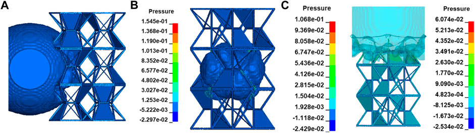
FIGURE 6. Explosion process of the UAV fuel tank structure. (A) Explosion location point 1. (B) Explosion location point 2. (C) Explosion location point 3.
There are many guiding inlets in the fuel tank structure of the complex UAV, which guide the explosion wave to converge or diverge after the external explosion. Whether it converges or diverges has a great relationship with the explosion location.
The spreading process of the explosion shock wave inside the model is shown in Figure 7. In Figure 7, when the charge explodes, it contacts the UAV fuel tank frame with the explosion wave. The deformation of the frame absorbs part of the energy, and some existing UAV fuel tank walls block the spreading of shock waves. When the explosion shock waves meet the structure like a funnel mouth, a jet is formed at the hole, and the shock waves converge and expand at a distance behind the wall through the hole and finally fill the whole space. In Figure 7A, the charge explodes. Because the charge is inside the UAV fuel tank structure and is affected by the structure, the explosion radiates outward under the guidance of the structure. Due to the explosion inside the structure, the whole structure is obviously damaged, and the skeleton is quickly crushed and broken. In Figure 7B, the charge explodes at the top. With the spreading of the explosion wave, it expands outward under the guidance of the shape of the UAV fuel tank skeleton, and the overall frame has good compressibility in the axial direction.
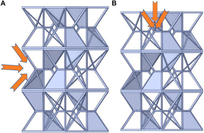
FIGURE 7. Section selection schematic diagram (left XY direction, right ZX direction). (A) Detonation wave convergence, (B) Detonation wave convergence.
In Figure 8, curves a and c have similar trends. From the location point of view, both of them play a certain role in weakening the explosion wave after structural crushing. The structures corresponding to a and c are crushed the most. The attenuation of explosion pressure is also the largest, showing the law that with the compression. When the explosion pressure is equal to the self-deformation force of the structure, the explosion pressure is the largest at this time, and then it begins to decelerate, reaching a stable state which means that the structure crushes to the limit. The energy absorption also reaches the limit, and the explosion pressure of the explosion wave tends to be stable. The explosion pressure in group A decreased rapidly from 150 Mpa to 70 Mpa and then increased briefly with the arrival of the reflected wave. The location of c is placed on the upper side, so the contact area is larger, the ability to block an explosion is stronger, and the explosion peak value is smaller. It is verified that the energy absorption of the structure is different when compressed in different directions.
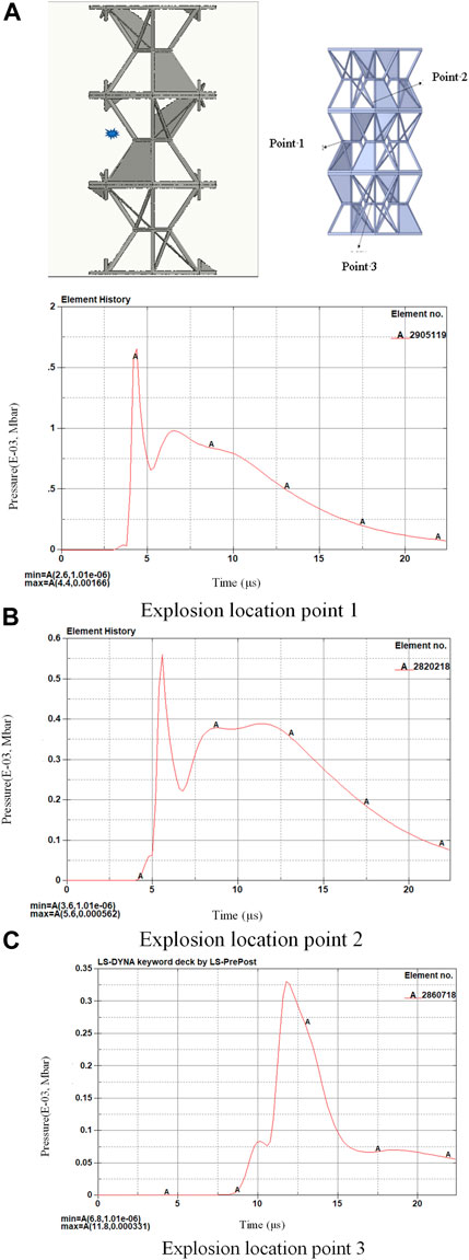
FIGURE 8. Overpressure at the measuring point in front of the UAV fuel tank structure. (A) Explosion location point 1. (B) Explosion location point 2. (C) Explosion location point 3.
Observing location B alone, because the explosion point is located inside the structure, the internal explosion is complex, and the space is small, the structure will be destroyed in a short time. It can be seen that in this case, the explosion attenuation is not obvious, this location explodes, and the explosion-proof ability of the structure is weak.
The simulated measured velocities at different observation points are shown in Figures 9–12. It can be seen that the process of the structure is very similar to the redistribution of deformation in a structural inhomogeneous body, which is consistent with the conclusion of Maruschak et al. (2012). Because locations of the explosion in Figures 13A,C are external, the speed increases all the time before they start to contact the frame. After contacting the UAV fuel tank frame, the frame starts to be compressed and the speed decreases obviously. After being compressed to a certain value, the whole structure is completely crushed, and the speed does not decrease. For Figure 13B, because of the small internal space, the velocity begins to decrease after loading to a certain value, and because the structure is destroyed prematurely, it does not play a good role in decreasing the explosion velocity.
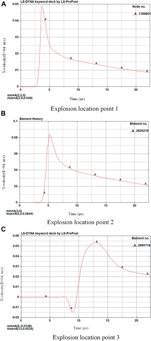
FIGURE 9. X-direction velocity of the measuring point in front of the UAV fuel tank structure. (A) Explosion location point 1. (B) Explosion location point 2. (C) Explosion location point 3.
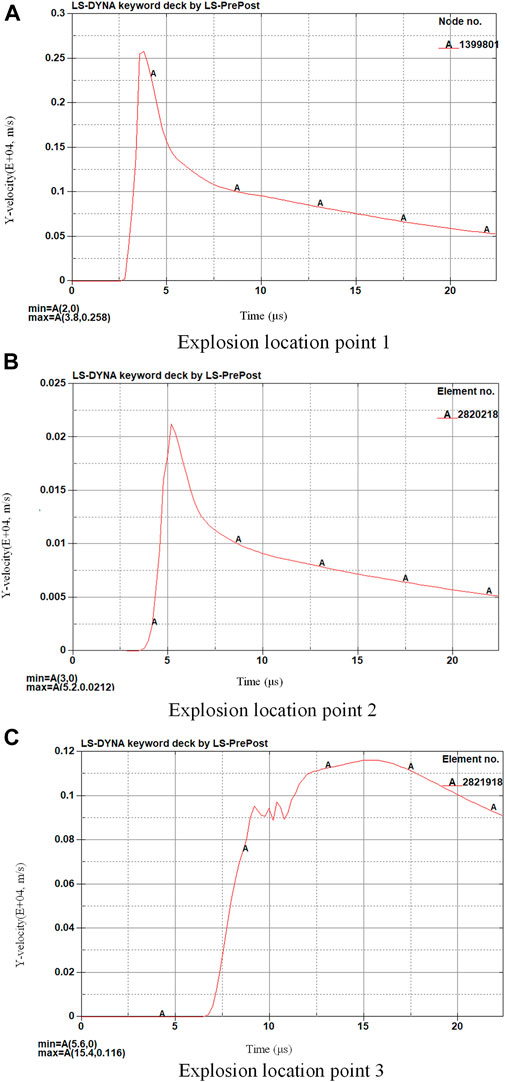
FIGURE 10. Y-direction speed of the measuring point in front of the UAV fuel tank structure. (A) Explosion location point 1. (B) Explosion location point 2. (C) Explosion location point 3.
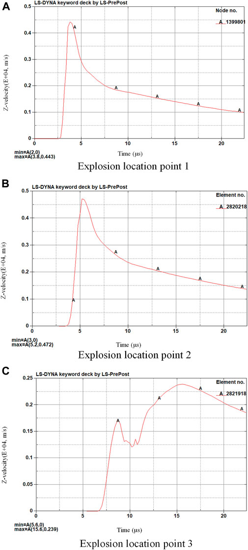
FIGURE 11. Z-direction velocity of the measuring point in front of the UAV fuel tank structure. (A) Explosion location point 1. (B) Explosion location point 2. (C) Explosion location point 3.
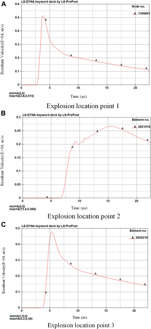
FIGURE 12. Total speed of measuring points in front of the UAV fuel tank structure. (A) Explosion location point 1. (B) Explosion location point 2. (C) Explosion location point 3.
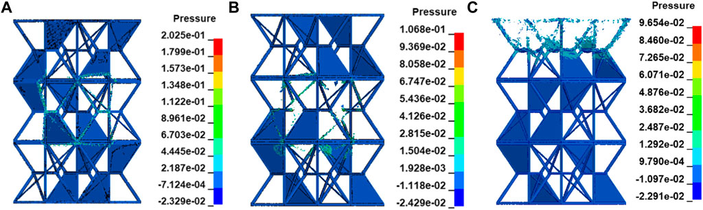
FIGURE 13. Explosion-proof stress nephogram of the UAV fuel tank structure. (A) Explosion location point 1. (B) Explosion location point 2. (C) Explosion location point 3.
It can be found from the explosion-proof stress nephogram shown in Figures 13–15 that the honeycomb barrier and explosion-proof structure of the UAV fuel tank can effectively block the high-speed and high-pressure fluid and shock waves produced by the explosion, greatly reduce the flow velocity, and prevent the rapid diffusion of the explosive fluid. The size of the low-flow velocity area formed by the honeycomb barrier and explosion-proof structure is closely related to the projection size of materials perpendicular to the flow velocity direction and the material connection strength between superimposed structures.
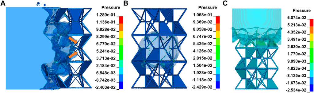
FIGURE 14. Explosion waveform after explosion-proof of the UAV fuel tank structure. (A) Explosion location point 1. (B) Explosion location point 2. (C) Explosion location point 3.
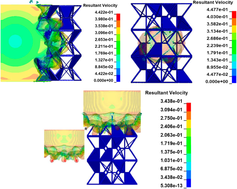
FIGURE 15. Explosion wave velocity nephogram during the explosion process of the UAV fuel tank structure.
According to the flow field shown in the given figure, the complex structure has more cavities which can diverge explosion waves when explosion waves enter large cavities from small calibers. On the contrary, it plays a convergent role.
Under the impetus of transverse and longitudinal explosion sources, the compression forms of the structure are different, the longitudinal compression performance is the best, which can bear greater explosion load, the transverse compression is limited, and the internal compression is the worst, which can easily cause damage prematurely and lose energy absorption. The honeycomb structure of the UAV fuel tank explosion-proof materials may cause the vortex growth of the fluid, but this phenomenon can be eliminated by stacking in large quantities.
When the honeycomb structure of the explosion-proof material impedes the high-speed and high-pressure fluid produced by the explosion, the main stress concentration area is the contact point of the structure, so it should be considered to improve the compressive strength of the structure by increasing the reinforcement.
The aforementioned analysis is based on a single structure. When there are many structures, the explosion wave continuously undergoes repeated processes such as convergence and divergence, and finally gets a greater weakening of explosion pressure, which plays a good explosion-proof role. When the number of structures reaches a certain amount, there is a high probability that any explosion point would have a corresponding structure to match it, and the explosion resistance performance of the UAV fuel tank structure of the group should be relatively stable.
The original contributions presented in the study are included in the article/Supplementary Material; further inquiries can be directed to the corresponding author.
CL and CW were responsible for the working concept or design; CW was responsible for data collection; XL was responsible for drafting the manuscript; GA made important revisions to the manuscript; and XX and YG were responsible for approving the final version to be published.
The authors declare that the research was conducted in the absence of any commercial or financial relationships that could be construed as a potential conflict of interest.
All claims expressed in this article are solely those of the authors and do not necessarily represent those of their affiliated organizations, or those of the publisher, the editors, and the reviewers. Any product that may be evaluated in this article, or claim that may be made by its manufacturer, is not guaranteed or endorsed by the publisher.
Bungartz, F. H. J. (2006). Fluid-Structure Interaction-modelling, simulation, optimization. Berlin, Heidelberg: Springer.
Chen, Z., and Kim, W-J. (2009). “Numerical simulation of flexible multi-assembled pipe systems subject to VIV,” in Proceeding of the 19th IOPEC, Osaka, Japan, July, 2009, 21–26.
Han, Z., LiFeng, X., Xiaobin, S., Yinzhong, Z., Bin, L., and Yulei, Z. (2011). Contrast studies on explosion suppression performance between spherical materials and reticular materials. Explos. Mateerials 40 (6), 15–18.
Liu, D., and Lin, P. (2008). A numerical study of three-dimensional liquid sloshing in tanks. J. Comput. Phys. 227 (8), 3921–3939. doi:10.1016/j.jcp.2007.12.006
Lucy, L. B. (1977). A numerical approach to the testing of the fission hypothesis. Astronomical J. 82, 1013–1024. doi:10.1086/112164
Maruschak, P. O., Konovalenko, I. V., and Bishchak, R. T. (2012). Effect of thermal fatigue cracks on brittle-ductile deformation and failure of cbcm roller surface layers. Metallurgist 56, 30–36. doi:10.1007/s11015-012-9532-9
Monaghan, J. J. (1988). An introduction to SPH. Comput. Phys. Commun. 48 (1), 89–96. doi:10.1016/0010-4655(88)90026-4
Paolo, E. (2010). Santangelo, Characterization of high-pressure water-mist sprays: Experimental analysis of droplet size and dispersion. Exp. Therm. Fluid Sci. 34, 1353–1366. doi:10.1016/j.expthermflusci.2010.06.008
Rabczuk, T., Xiao, S. P., and Sauer, M. (2006). Coupling of mesh-free methods with finite elements: Basic concepts and test results. Commun. Numer. Methods Eng. 22 (10), 1031–1065. doi:10.1002/cnm.871
Keywords: UAV fuel tank, honeycomb barrier and explosion-proof structure, fluid structure coupling, stress-strain, choke flow analysis
Citation: Wang C, Lu C, Lin X, An G, Xu X and Gan Y (2022) Force analysis of the explosion-proof structure of a UAV fuel tank based on the fluid structure coupling method. Front. Mater. 9:886150. doi: 10.3389/fmats.2022.886150
Received: 08 March 2022; Accepted: 26 July 2022;
Published: 31 August 2022.
Edited by:
Roberto Brighenti, University of Parma, ItalyReviewed by:
Pavlo Maruschak, Ternopil Ivan Pului National Technical University, UkraineCopyright © 2022 Wang, Lu, Lin, An, Xu and Gan. This is an open-access article distributed under the terms of the Creative Commons Attribution License (CC BY). The use, distribution or reproduction in other forums is permitted, provided the original author(s) and the copyright owner(s) are credited and that the original publication in this journal is cited, in accordance with accepted academic practice. No use, distribution or reproduction is permitted which does not comply with these terms.
*Correspondence: Chunzhi Wang, MTE1MDM0MDIxOEBxcS5jb20=
Disclaimer: All claims expressed in this article are solely those of the authors and do not necessarily represent those of their affiliated organizations, or those of the publisher, the editors and the reviewers. Any product that may be evaluated in this article or claim that may be made by its manufacturer is not guaranteed or endorsed by the publisher.
Research integrity at Frontiers
Learn more about the work of our research integrity team to safeguard the quality of each article we publish.