 Zikui Shen
 YanPeng Hao1
 Xilin Wang
95% of researchers rate our articles as excellent or good
Learn more about the work of our research integrity team to safeguard the quality of each article we publish.
Find out more
ORIGINAL RESEARCH article
Front. Mater. , 19 April 2022
Sec. Polymeric and Composite Materials
Volume 9 - 2022 | https://doi.org/10.3389/fmats.2022.877159
This article is part of the Research Topic Advanced Technologies for Electrical Engineering View all 6 articles
Electric field distribution along gas–solid interfaces determines the reliability of insulating components. However, the dielectric gradient insulating component prepared by the conventional method is considered to only control the internal electric field, but is not beneficial to the surface insulation, especially when the electrode is at an acute angle from the dielectric surface. The aim of this study is to clarify that the meta-structure surface based on dielectric tensor rotation constructed by the electric field-induced assembly (EIA) method could improve surface insulation. The self-assembly and orientation axis rotation of filler particles near the interface were observed by in-situ optical observation, and the relationship between the dielectric tensor rotation and electric field refraction was revealed. Simulation of meta-structure surface induced by the EIA method on the basin insulator was conducted. The meta-structure surface exhibits negative and high reduced permittivity, confining electric field path and transferring the electrical stress from gas to insulator, which offers theoretical support to optimize the surface electric field. Flashover tests on the basin insulator proved the insulation improvement by meta-structure surface.
How to withstand the higher voltage using the same insulation distance is a focus throughout the era of electrical energy. There was general agreement that homogenizing the electric field to take full advantage of the insulation distance can avoid the “barrel effect" (Cigré 2014; Cigré 2020; Li et al., 2020). The conventional insulation design aims to optimize the topology of electrodes, which increases the complexity of the structure and has a limited effect on electric field mitigation. In recent years, researchers have focused on dielectric functional gradient materials (d-FGM), which use the gradient distribution of dielectric parameters to mitigate the spatial electric field and have a widespread application prospect. In Cigre’s report of 2017, the effectiveness of d-FGM in modulating electric fields was fully recognized. The fabrication methods that have been developed can be divided into two main categories: (1) “building block” methods, including lamination (Brealey et al., 1982), magnetron sputtering (Du et al., 2020), flexible casting (Hayakawa et al., 2018), and 3D printing (Li et al., 2019), and (2) energy field assisted methods, which use an external energy field to manipulate the filler particle distribution during the casting of insulating components, including centrifugation (J. Ishiguro et al., 2014), electrophoresis (Diaham et al., 2021; Diaham et al., 2021; Diaham et al., 2021), magnetophoresis (Tommaso Nardi et al., 2016), and electric field-induced assembly (EIA) method (Shen et al., 2020; Shen et al., 2021; Shen et al. 2022). The first type of methods cannot deal with more complex space electric fields, and the second type of methods’ applicability depends on the similarity of the applied energy field to the operating electric field.
Maxwell–Wagner polarization occurs at the interface due to differences in the dielectric parameters of the filler and the matrix. Polarized fillers interact with each other in the electric field and assemble in chains along the direction of the electric field, resulting in the increased effective permittivity of the composite in the electric field direction (Singh et al., 2019; Shen et al., 2021), i.e., the electric field-induced self-assembly effect. The higher the applied field strength, the faster the alignment of the chains and the faster the corresponding increase of the permittivity. If an assistant AC electric field similar to the spatial distribution of the actual working electric field is applied to the prepolymer state during the casting of the insulator to induce self-assembly of the internal filler of high permittivity, due to the inhomogeneity of the electric field, the self-assembly speed and the corresponding growth rate of the effective permittivity vary with space. By controlling the action time of the assistant electric field, the obtained permittivity gradient satisfies the stronger the electric field, the higher the permittivity, which helps to mitigate the electric field. This is the principle of the EIA method (Shen et al., 2021).
However, the dielectric gradient is generally considered to control the internal electric field of the components, but not beneficial to the surface insulation, especially when the electrode is at an acute angle with the insulating components, the dielectric gradient will enhance the electric field on the gas side, which is prone to trigger the flashover. As a key insulating component of high voltage transmission, more than half of the failure of basin insulators are caused by flashover on the concave surface. Thus it is urgent to regulate the surface electric field. In this paper, a method was proposed to construct a meta-structure surface based on the rotation of the dielectric tensor induced by the AC electric field, to confine the electric field path and improve the surface insulation. This method is expected to broaden the application of the EIA method.
In the electric field, the suspended spherical dielectric particle is polarized and the dipole moment is (Thomas 1995)
For 1D rod-like particles, the dipole moment can be calculated approximately based on the ellipsoidal particles (a>b = c). Decomposing the electric field
where
where
The polarized particles will be subjected to dielectrophoretic force due to the electric field gradient, for transmission and substation insulation systems, where the electric field is slightly inhomogeneous, the dielectrophoretic force generated by the applied electric field can be neglected. However, neighboring fillers (as shown in the figure) will interact with each other and the electrostatic force expression is
Figure 1shows the relationship between the electrostatic force and the angle. When
where
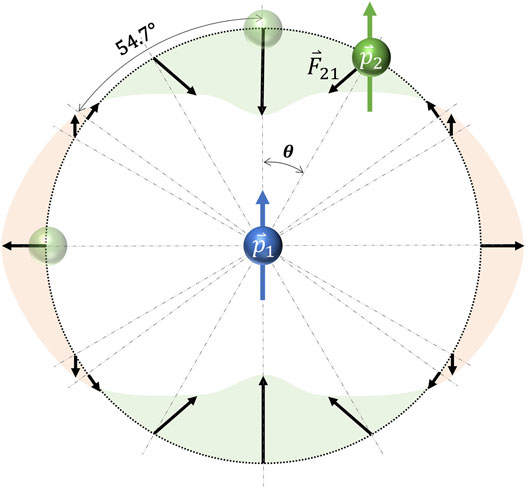
FIGURE 1. Spatial position of parallel isotropic dipole and variation of force with angle.
Fillers go from disorder to fully self-assembly in a time-domain process, due to electrostatic force and viscous drag. Figure 2 shows the schematic diagram of particle orientation as well as complete self-assembly. The change of microstructure is inevitably mapped to macroscopic properties, and the previous work found that the effective permittivity of liquid composites will first increase and then stabilize in a uniform AC electric field. The transient process of the effective permittivity of the liquid prepolymer composites in a uniform AC electric field satisfies (Shen et al., 2021)
where
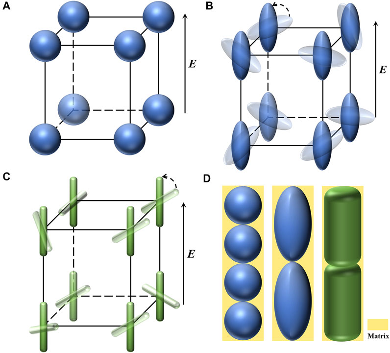
FIGURE 2. Orientation and self-assembly of fillers (A), spheres (B), ellipsoid (C), and rod-like particle (D) fully aligned along the electric field.
The fabrication steps for typical composite insulating components, such as basin insulators, can be summarized as (1) pouring the liquid prepolymer composite into a casting mold with electrodes embedded and (2) curing the material. If in the first step, an alternative (AC or bipolar repetitive pulse) voltage is applied through the embedded electrodes, then a nonuniform electric field will be generated inside the liquid prepolymer composites. According to the above theory, the speed of transient process of permittivity varies in different areas, and the permittivity changes faster in high field strength areas and slower in other areas. According to Maxwell’s equations, the space electric field satisfies
The kinetic equation for the evolution of the permittivity here is (Shen et al., 2021)
The dielectric gradient built by the EIA method is adaptive to the real electric field. In (Shen et al., 2021), it is confirmed by simulation that, if a suitable operating time is chosen, the gradient permittivity constructed by the EIA method can significantly mitigate the internal electric field, regardless of the number and distribution of high field strength regions.
Conventional dielectric gradient components are locally isotropic, while components prepared by the EIA method are locally anisotropic with a second-order dielectric tensor, as shown in thefollowing equation:
where
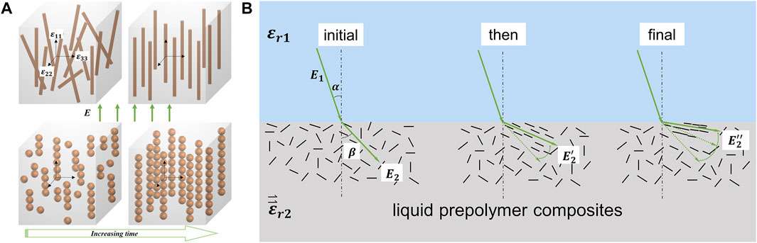
FIGURE 3. Changes in magnitude and direction of the dielectric tensor: (A) self-assembly process of fillers in an electric field; (B) rotation of orientation axis of fillers near the interface.
The polarization of the medium is
where
Electric torque drives the dielectric tensor to rotate to reduce
TiO2w with an average diameter of 300 nm and an average length of 5 μm, was purchased from Shanghai Haoxi Nano Technology Co., Ltd.; α-Al2O3 with an average diameter of 20 μm was purchased from Guangzhou Nanuo Chemistry Co., Ltd. Dimethyl silicone oil with a viscosity of 1000 mPa.s at room temperature, was purchased from Dow Corning. The EP (E39) and methyl-hexahydrophthalic anhydride (MeHHPA) were purchased from Jining Huakai Co., Ltd. Benzyldimethylamine (BDMA) was used as the catalytic agent.
To investigate the typical process of dielectric tensor rotation, an online optical observation system was developed. Figure 4 shows the schematic diagram of the experimental setup. A square transparent glass plate surface was attached with 1 mm thick copper electrodes at both ends and a 1 mm thick biaxially oriented polypropylene (BOPP) film on the rest area (a 1 mm wide gap was left diagonally, filling with 1vol% TiO2w/silicone oil mixture). Briefly, a 10 kHz AC voltage (RMS of 1kV) is applied through the electrodes for 1 min while the filler distribution near the interface is observed using an optical microscope.
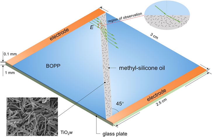
FIGURE 4. Experimental setup for online observation of tensor rotation.
All simulations are based on the Electrostatic module and the Domain Ordinary Differential Equation (DODE) module in COMSOL Multiphysics.
First step: we simulate the spatiotemporal evolution of the permittivity due to electric field-induced self-assembly of fillers for liquid prepolymer composite components in the mold. Since the principal axis of the dielectric tensor wherever in this process are isotropic with the electric field, there is no need to consider the effect of the tensor, just enter the scalar function
Second step: we simulate the effect of the cured polymeric component on the operating electric field. In practical application, the mold material is replaced with other dielectrics such as air. Due to the curing reaction, the permittivity of the composite component drops. This effect is isotropic and a constant for the same matrix
To investigate the improvement of the insulation performance by the meta-structured surface based on the dielectric tensor rotation, we prepared scaled-down basin insulators by the EIA method. In the EIA method, high-frequency AC assistant voltage is preferred because it both reduces Joule heating and suppresses filler electrophoresis (Liu et al., 2018). One-dimensional (1D) high permittivity fillers (except carbon) are preferred because of their high self-assembly efficiency and the large improvement in the effective permittivity of the composite after self-assembly (Shen et al., 2022). The low filler content is also preferred to reduce the effect on the dielectric loss and breakdown field strength of the composite insulation material.
The cross section of the basin insulator is shown in the figure. In the factory, liquid epoxy composites are poured into the mold with embedded electrodes and then cured to form basin insulators. In the EIA method, the material of the mold is replaced from metal to PTFE, and a 10 kHz AC voltage is applied during the liquid state through the embedded electrodes to induce filler self-assembly and construct the bulk dielectric gradient as well as the meta-structure surface, as shown in Figure 5A. Compared to the preparation process, the permittivity changes on both sides of the interface when used. On one side,
FIGURE 5. Experimental setup for fabrication of basin insulators by EIA method: (A) cross-sectional schematic; (B) optical image of the setup.
The above process was simulated using COMSOL Multiphysics, as described in (Shen et al., 2021). Casting composition is E39/Al2O3/TiO2w (mass ratio of 100:300:15), according to a previous experimental study (Shen et al., 2022),
The fabrication setup of the insulator is shown in Figure 5B. The TiO2w/Al2O3/E39/MeHHPA (mass ratio of 15:300:100:66) was stirred for 10 min using a machine and then put into a vacuum oven to defoam three times, each time lasting 5 min. Added 2 phr of BDMA (relative to E39) to the mixture, stirred well, and then poured into the PTFE mold with electrodes from the pouring port; left it at room temperature 2 h, then applied 1.5 kV/10 kHz AC voltage on the inner electrode for 200 s and next to the voltage was reduced to 40 V for 6 h; after that, turned off the voltage and left the setup at room temperature for 16 h; finally, the mold was placed in an oven to cure (35°C for 2 h and 120°C for 2 h). Control samples without assisted voltage were prepared according to the same procedure.
According to IEC 60243–1:2013, we performed the short-time 50 Hz flashover test with a rate of increase of 500 V/s. The voltage waveform collected by the oscilloscope and the arc are used to determine whether a flashover has occurred. Eight replicate experiments were performed for each sample, with two flashover intervals of 5 min.
Figure 6A shows the typical image of the filler distribution at the initial moment. As the voltage action time increases, the fillers near the interface gradually self-assemble and the orientation axis rotates. We used FibrilTool, an ImageJ plug-in to quantify fibrillar structures in microscopy images (Boudaoud et al., 2014), including the anisotropy and average direction of the region of interest, as shown in Figures 6B,C. The anisotropy score follows the convention: 0 for no order and 1 for perfectly ordered (see Boudaoud et al. (2014) for detailed image processing algorithms).
FIGURE 6. Optical image near the interface of the setup in Figure 4. (A) Initial time, (B) middle time, and (C) final time. (B,C) are output from FibrilTool: a line segment (green) is drawn, the angle of which represents the average orientation of the array and the length of which is proportional to the array anisotropy, the polygon represents the region of interest.
Figures 6B,C show the filler orientation and anisotropy at different distances from the interface, which is a visualization of the electric field lines. There is a little mixture on the BOPP on the left side of the interface that cannot be completely erased, which does not affect the permittivity of the BOPP, but helps us to determine the direction of incidence of the electric field. In Figure 6B, the incidence angle and the refraction angle between the interface are 36.4° and 72.9°, respectively. As time goes by, these two angles become 39.2° and 79.9°, respectively, as shown in Figure 6C.
When the electric field is along the tensor axis or the medium is isotropic, the electric field refraction at the interface satisfies
where
When
FIGURE 7. Results of simulation. (A) The direction of local filler orientation (angle to horizontal axis), (B) composite’s effective permittivity in the direction of local filler orientation, (C) electric field in the original insulator, (D) electric field in the insulator fabricated by the EIA method, and (E) electric field along the concave surface of the basin insulator.
Figure 8A presents the incidence and refraction angles along the concave interface for two kinds of basin insulators. The incidence and refraction angles of the insulator with super-structure surface are higher than those of homogenous insulators, i.e., the angle between the electric field and the surface decreases on the gas side (the blue area). The reduced permittivity of the interface dielectric tensor is calculated according to Eq. (17), as shown in Figure 8B. The closer to the inner electrode, the higher the reduced permittivity (up to 9). It exhibits negative and high values near the normalized radius of 0.2. In general, the negative permittivity is achieved by filling the metal (Wang et al., 2020). The negative reduced permittivity here may be generated due to the overall microstructure. The high permittivity means that the refractive electric field is approximately parallel to the interface, and the negative means that the normal electric field after refraction is reversed. By regulating the incidence and refraction angles of the electric field at the gas–solid interface, the meta-structure surface confines the electric field path and transfers the electric field stress from the gas to the insulator.
FIGURE 8. Effect of meta-structure surface on electric field and flashover voltage: (A) incidence and refraction angles (relative to the normal direction) along the concave interface, (B) reduced permittivity of the interface dielectric tensor, and (C) Weibull plot of the flashover voltage of the basin insulators.
Researchers employed the support vector regression (SVR) method based on mass experimental data to predict the flashover voltage, indicating that flashover voltage is affected not only by the maximum electric field but also by multiple features of the surface electric field (Liu et al., 2019). Flexible modulation of the electric field (including incidence angle) by the meta-structure surface, combined with the data-driven predicting models, can help reduce test work during acceptance testing, which could substantially reduce the economic cost. Improved insulation of the meta-structure surface induced by EIA method was experimentally verified by (Shen et al., 2022), as shown in Figure 8C, with a 12.7% increase in flashover voltage on clean surfaces and a 20.8% increase while there is a metal particle near the ground electrode.
The meta-structure surface of insulating components based on dielectric tensor rotation induced by the EIA method can achieve high or negative reduced permittivities to constrain the electric field paths and transfer the electric field stresses from the triple junction point. The meta-structure surface can also affect the angle between the electric field and surface on both sides of the interface, improving the surface insulation. With the help of the above analysis and the modeling of the EIA method, researchers can easily formulate a scheme to optimize the electric field of the specific insulating component (including filler selection, assistant voltage magnitude, and action time). Further developments of the proposed idea of the meta-structure surface would potentially transform the insulating components in high-voltage applications and expand the frontiers of dielectrics for the power industry.
The raw data supporting the conclusions of this article will be made available by the authors, without undue reservation.
ZS: data curation and writing the original draft; YH: supervision; ZX: data curation and formal analysis; XW: investigation, methodology, and project administration; and ZJ: project administration and supervision. All authors contributed to manuscript revision and read and approved the submitted version.
This work was supported by the National Natural Science Foundation of China (No. 52177021) and Shenzhen fundamental research and discipline layout project (No. JCYJ20180508152044145).
The authors declare that the research was conducted in the absence of any commercial or financial relationships that could be construed as a potential conflict of interest.
All claims expressed in this article are solely those of the authors and do not necessarily represent those of their affiliated organizations, or those of the publisher, the editors, and the reviewers. Any product that may be evaluated in this article, or claim that may be made by its manufacturer, is not guaranteed or endorsed by the publisher.
Boudaoud, A., Burian, A., Borowska-Wykręt, D., Uyttewaal, M., Wrzalik, R., Kwiatkowska, D., et al. (2014). FibrilTool, an ImageJ Plug-In to Quantify Fibrillar Structures in Raw Microscopy Images. Nat. Protoc. 9 (2), 457–463. doi:10.1038/nprot.2014.024
Brealey, R. H., Juneau, P. W., and Zlupko, J. E. (1982). Fabrication Design and Electrical Evaluation of Bulk-Graded Filled Polymer post Insulators, in 1982 IEEE International Conference on Electrical Insulation, Philadelphia, PA, USA, June 7-9, 1982. (Piscataway, New Jersey, United States: IEEE), 225–228. doi:10.1109/EIC.1982.7464475Available at: http://ieeexplore.ieee.org/document/7464475/
Diaham, S., Valdez-Nava, Z., Le, T. T., Leveque, L., Laudebat, L., and Lebey, T. (2021). Field Grading Composites Tailored by Electrophoresis-Part 2: Permittivity Gradient in Non-uniform Electric Field. IEEE Trans. Dielect. Electr. Insul. 28 (2), 341–347. doi:10.1109/TDEI.2020.009031
Diaham, S., Valdez-Nava, Z., Le, T. T., Leveque, L., Laudebat, L., and Lebey, T. (2021). Field Grading Composites Tailored by Electrophoresis-Part 3: Application to Power Electronics Modules Encapsulation. IEEE Trans. Dielect. Electr. Insul. 28 (2), 348–354. doi:10.1109/TDEI.2020.009032
Diaham, S., Valdez-Nava, Z., Leveque, L., Le, T. T., Laudebat, L., and Lebey, T. (2021). Field Grading Composites Tailored by Electrophoresis - Part 1: Principle and Permittivity Gradient in Uniform Electric Field. IEEE Trans. Dielect. Electr. Insul. 28 (2), 333–340. doi:10.1109/TDEI.2020.009030
Du, B. X., Wang, Z. H., Li, J., Liang, H. C., and Li, Z. H. (2020). Epoxy Insulator with Surface Graded-Permittivity by Magnetron Sputtering for Gas-Insulated Line. IEEE Trans. Dielect. Electr. Insul. 27 (1), 197–205. doi:10.1109/TDEI.2019.008385
Ishiguro, J., Kurimoto, M., Kojima, H., Kato, K., Okubo, H., and Hayakawa, N. (2014). “Electric Field Control in Coaxial Disk-type Solid Insulator by Functionally Graded Materials (FGM).” in Proceedings of the 2014 Annual Report Conference on Electrical Insulation and Dielectric Phenomena, Des Moines, IA, USA, October 2014.
Li, J., Liang, H., Chen, Y., and Du, B. (2020). Promising Functional Graded Materials for Compact Gaseous Insulated Switchgears/pipelines. High Voltage 5 (3), 231–240. doi:10.1049/hve.2019.0327
Li, X.-R., Liu, Z., Li, W.-D., Sun, G.-Y., Xue, J.-Y., Wang, C., et al. (2019). 3D Printing Fabrication of Conductivity Non-uniform Insulator for Surface Flashover Mitigation. IEEE Trans. Dielect. Electr. Insul. 26 (4), 1172–1180. doi:10.1109/TDEI.2019.007938
Liu, L., Chen, K., Xiang, N., and Ni, Z. (2018). Dielectrophoretic Manipulation of Nanomaterials: A Review. Electrophoresis 40 (6), 873–889. doi:10.1002/elps.201800342
Liu, L., Li, X., Wen, T., Zhang, R., Wu, Z., Zhao, J., et al. (2019). Investigation on Surface Electric Field Distribution Features Related to Insulator Flashover in SF6 Gas. IEEE Trans. Dielect. Electr. Insul. 26 (5), 1588–1595. doi:10.1109/TDEI.2019.008194
Luo, S., Shen, Y., Yu, S., Wan, Y., Liao, W.-H., Sun, R., et al. (2017). Construction of a 3D-BaTiO3 Network Leading to Significantly Enhanced Dielectric Permittivity and Energy Storage Density of Polymer Composites. Energy Environ. Sci. 10 (1), 137–144. doi:10.1039/c6ee03190k
Hayakawa, N., Miyaji, Y., Kojima, H., and Kato, K. (2018). Simulation on Discharge Inception Voltage Improvement of GIS Spacer with Permittivity Graded Materials (ε-FGM) using Flexible Mixture Casting Method. IEEE Trans. Dielect. Electr. Insul. 25 (4), 1318–1323. doi:10.1109/TDEI.2018.007236
Nardi, T., Mora, N., Rachidi, F., and Leterrier, Y. (2016). Graded-permittivity Polymer Nanocomposites as superior Dielectrics. Composites Sci. Tech. 129 (6), 1–9. doi:10.1016/j.compscitech.2016.04.010
Shen, Z., Jia, Z., Hao, Y., Xin, Z., and Wang, X. (2022).A Fabrication Method for Adaptive Dielectric Gradient Insulating Components. High Voltage. In press. doi:10.48550/arXiv.2112.00896
Shen, Z., Wang, X., Xin, Z., Zhang, T., Xu, C., and Jia, Z. (2021). Analytical Model for the Spatiotemporal Permittivity of uncured-Composite Devices in an AC Electric Field. J. Phys. D: Appl. Phys. 54 (15), 155302. doi:10.1088/1361-6463/abd9a7
Shen, Z., Wang, X., Zhang, T., and Jia, Z. (2020). In Situ electric Field Driven Assembly to Construct Adaptive Graded Permittivity BaTiO3/epoxy Resin Composites for Improved Insulation Performance. Appl. Mater. Today 20, 100647. doi:10.1016/j.apmt.2020.100647
Shen, Z., Xin, Z., Wang, X., Wei, X., and Jia, Z. (2021). Analytical Model for the Transient Permittivity of uncured TiO 2 Whisker/liquid Silicone Rubber Composites under an AC Electric Field. High Voltage 6 (3), 470–479. doi:10.1049/hve2.12060
Singh, S. K., Aryaan, N., Shikder, M. R. A., Byles, B. W., Pomerantseva, E., and Subramanian, A. (2019). A 3D Nanoelectrokinetic Model for Predictive Assembly of Nanowire Arrays using Floating Electrode Dielectrophoresis. Nanotechnology 30 (2), 025301. doi:10.1088/1361-6528/aae9a4
Verrelli, D. I. (2014). Convenient Formulæ for the Drag on a Prolate Ellipsoid Moving along its axis of Symmetry Perpendicular to a Plane Surface. Int. J. Multiphase Flow 65, 138–142. doi:10.1016/j.ijmultiphaseflow.2014.05.010
Keywords: self-assembly, electric polarization, dielectric tensor, surface insulation, meta-surface, functional gradient material, basin insulator
Citation: Shen Z, Hao Y, Xin Z, Wang X and Jia Z (2022) Meta-Structure Surface Based on Dielectric Tensor Rotation Induced by AC Electric Field for Insulation Improvement. Front. Mater. 9:877159. doi: 10.3389/fmats.2022.877159
Received: 16 February 2022; Accepted: 21 March 2022;
Published: 19 April 2022.
Edited by:
Jun-Wei Zha, University of Science and Technology Beijing, ChinaReviewed by:
Yifei Wang, University of Connecticut, United StatesCopyright © 2022 Shen, Hao, Xin, Wang and Jia. This is an open-access article distributed under the terms of the Creative Commons Attribution License (CC BY). The use, distribution or reproduction in other forums is permitted, provided the original author(s) and the copyright owner(s) are credited and that the original publication in this journal is cited, in accordance with accepted academic practice. No use, distribution or reproduction is permitted which does not comply with these terms.
*Correspondence: Zhidong Jia, amlhemRAc3oudHNpbmdodWEuZWR1LmNu
Disclaimer: All claims expressed in this article are solely those of the authors and do not necessarily represent those of their affiliated organizations, or those of the publisher, the editors and the reviewers. Any product that may be evaluated in this article or claim that may be made by its manufacturer is not guaranteed or endorsed by the publisher.
Research integrity at Frontiers
Learn more about the work of our research integrity team to safeguard the quality of each article we publish.