 Li Chen
 Tianqi Wang1
94% of researchers rate our articles as excellent or good
Learn more about the work of our research integrity team to safeguard the quality of each article we publish.
Find out more
ORIGINAL RESEARCH article
Front. Mater. , 28 March 2022
Sec. Structural Materials
Volume 9 - 2022 | https://doi.org/10.3389/fmats.2022.876111
This article is part of the Research Topic Advanced Steel and Composite Structures in Civil Engineering View all 9 articles
This paper mainly explores the distribution of welding residual stress of U-rib stiffened plates of steel box girders and examines the influence of welding residual stress over the natural frequencies of these plates. The research focuses on two aspects, namely, the distribution of welding residual stress, and the dynamic behavior of U-rib stiffened plates in the context of that distribution. Firstly, we build two finite element models to analyses the welding process and study the dynamic behavior. Next, the authors discussed how different geometric parameters, as well as welding parameters, affect the residual stress distribution. In addition, the welding residual stress curves were fitted for steel box girders of varied sizes, and a simplified formula was deduced for the distribution of welding residual stress. After that, the simplified formula was applied to analyze the natural frequencies of stiffened plates in multiple sets of models. Through the analysis of natural frequency under different boundary conditions, it was learned that the welding residual stress has a remarkable influence on the natural frequencies of stiffened plates.
Over the past few decades, steel box girders have been widely employed in long-span bridges. Each steel box girder mainly consists of stiffened plates that contain welding residual stresses. How residual stresses affect the stiffened plates has attracted extensive attention from researchers. The bridge deck, which rests on the girders, carry most of the various traffic loads on the bridge structure (Cui et al., 2018a). However, the existing studies have not fully grasped the natural frequencies of stiffened plates under complex conditions, and the experimental data are insufficient due to high measuring errors. It is necessary to consider the residual stress in welding process because of the welding deformation. Generally speaking, residual stress is considered to be detrimental to the structure, it will affect the fatigue of the structure, the yield limit of the material, the brittle failure of the metal, and the corrosion cracking. It is obvious that the study of residual stress is a key factor in studying the influence of the structure. Study on residual stress should be an important part in this paper.
In addition, it is difficult to predict the residual stresses accurately in the past. In the present study, machine learning algorithms have been used to predict residual stress and natural frequency of vibrations (Das et al., 2020a).Therefore, it is extremely important to examine the natural frequencies of stiffened plates in the context of residual stresses.
Much research has been done on the influence of the welding process over the residual stress distribution in various welding structures (El-Axir, 2002; Zhao and Wu, 2012a; Lin and Yang, 2014; Wu and Kim, 2018; Zheng et al., 2018). But most of the published works are not deep enough into U-rib stiffened plates. The predictions on residual stress distribution are inconsistent with the actual situation.Ohashi et al. (1996) measured the residual stresses of the trapezoidal rib stiffened plates of Duodoro Bridge, and, on this basis, proposed a model to calculate the distribution of residual stresses.
Owing to high cost and large data dispersion, it is a challenge to capture the true distribution of residual stresses through experiments (Deng and Murakawa, 2006; Qiang et al., 2018; Rikken et al., 2018; Salerno et al., 2018). The computer-aided technique provides an economical and effective way to simulate the welding residual stresses (Fujikubo and Yao, 1999; Gannon et al., 2010; Cui et al., 2018b; Gadallah et al., 2018; Jiang et al., 2018). Zhao and Wu (Zhao and Wu, 2012b) simulated the welding temperature field and stress field, calculated the residual stress of the U-rib stiffened plates, and derived the residual stress distribution related to U-rib thickness and plate thickness.
In 1974, Herrmann and Brunelle demonstrated that the residual stresses affect the stiffness, which in turn impacts the dynamic behavior of isotropic welded plates. Since then, many researchers have investigated the effects of residual stress on various structures, and even on micro structures (Olfatnia et al., 2010; Wang and Wang, 2012; Yang et al., 2019). F. Wu (Wu, 1999) theorized that thermal residual stresses significantly affect the natural frequencies, and thermal residual stresses can be tailored to increase natural frequencies. Das, D and Pratihar, D.K (Das et al., 2020b) find a correlation between the measured welding stress and natural frequency of vibration.
Lieven and Greening (2001); Ballestra et al. (2008) illustrated that the changes in resonance behavior resulting from pre-stress offer exciting prospects in model analysis, and experimentally proved that the natural frequencies are affected by the residual stress.
In actual engineering, the diversity of welding parameters adds difficulty to the implementation of the accurate distribution law of residual stress of the welding structures. In most cases, the residual stress distribution is very complicated. To solve these issues, this paper simulates the welding process of U-rib stiffened plates with changing welding parameters. After determining the stress field, the authors plotted the fitting curve, and presented a simplified distribution formula. Taking the Hong Kong-Zhuhai-Macao Bridge as the engineering background, this paper relies on the simplified formula and shell model analysis to investigate how welding residual stress influences the natural frequencies of stiffened plates of steel box girders.
Welding is the most common technique to join two components together. As is known to all, the finite-element analysis of U-rib stiffened plates usually adopts shell elements. However, the shell elements are not suitable for analyzing the process of thermal welding. To solve the problem, this paper proposes a 3D solid element type in the welding model to investigate the welding process, and thereby extract the distribution of residual stresses. Figure 1 shows the Simufact model of the U-rib stiffened plates, which are on the thick yellow platform prepared for welding. Note that fixing-4 and fixing-5 are fixed boundary conditions, both of which are constrained in the x-direction. At the beginning of the welding, the U-rib stiffened plates were laid down on the bearing. All the boundary conditions were kept constant until the end of the cooling process. After setting all the geometries and material proprieties, two welding robots began to work along the weld line. The robots weld independently of each other, with a 200 s cooling period between them. The total working time of each robot is the same. The entire process lasted 3,000s, until the temperature dropped to 20°C.
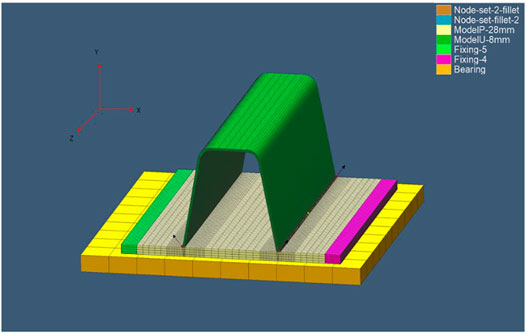
FIGURE 1. The Simufact model of the U-rib stiffened plates.
Figure 2 details the cross-section of the U-rib stiffened plates. The width, i.e., the x-direction dimension in the finite-element model, and the height, i.e., the y-direction dimension in the finite-element model, are 600 and 300 mm, respectively. The U-rib thickness varies from 6 to 24 mm, while the master plate thickness varies from 18 to 24 mm. It is assumed that each U-rib stiffened plate is made of the same material, with the welding progressing from the purple side to the light green side. The density, elastic modulus, and Poisson’s ratio are denoted by ρ, E, and μ, respectively, the thickness of the U-rib as t1, the thickness of the master plate as t2, and the width of the model as t3. In actual welding of U-rib stiffened plates, partial penetration is often adopted. Our simulation considers only one-bead pass.
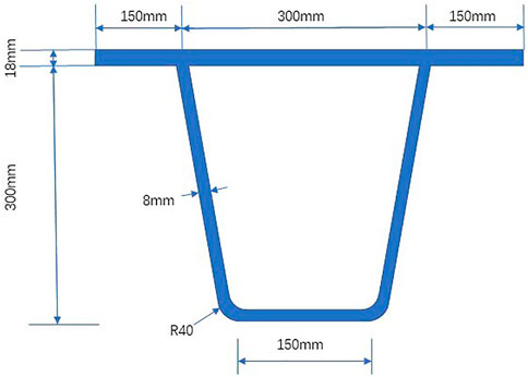
FIGURE 2. Cross-sectional view of the U-rib stiffened plates.
The numerical simulation of welding begun in the 1970s, when Japanese researchers Ueda and Yamakawa proposed the thermoplastic finite-element method (FEM). Considering the variation of materials with temperatures, the basic theory of dynamic residual stress in welding (Ueda and Yamakawa, 1971) can be described as:
where,
If the material is in an elastic phase, then
where,
The value of
where, S =
Multiplying both sides of Eq. 3 by D, and substituting the result into Eq. 2:
During plastic molding, it is necessary to consider the plastic strain
Considering the flow rule and the von Mises yield criterion, the constitutive relationship can be expressed as:
where,
The welding materials are the same as the steel box girders of Hong Kong-Zhuhai-Macao Bridge. The primary material is Q345qD U-rib stiffened plates. The welding rods are of the material E5015. The material properties vary with temperatures. The thermodynamic property is an important parameter to predicting the distribution of residual stress.
Before predicting the residual stress, transient thermal analysis should be conducted to derive the temperature field during welding. The governing equation for the transient temperature field can be expressed as:
where
The internal heat Q can be defined as:
where, U is the voltage; I is the current;
According to the Goldak heat source model, the distribution can be expressed as:
where,
The concept of heat source aims to model the isothermal surface of the real melt pool. The software Simufact Welding provides a conventional model introduced by Goldak et al. (Goldak et al., 1984) for arc welding.
Material properties are the key in FE simulation of welding process. Q345qD is a widely used material among Chinese bridges, as per Structural Steel for Bridge(GB/T 714-2015). But the experimental data on the thermodynamic properties of Q345qD are rare and insufficient. JMatPro is a commercial material property software for thermal parameter calculation. It can provide data on thermodynamic properties regarding temperature change. According to the various components in Q345qD steel, the thermal-physical material properties can be obtained between 200°C and 2,000°C. This approach has been widely accepted in the steel industry, owing to its high efficiency, economy, and stability (Saunders et al., 2003). It can be learned that the materials in the master plate and U-ribs have the same properties. The phase transformation calculated by JMatPro is also crucial to the analysis on the material properties of Q345qD.
The welding parameters and heat source parameters are listed in Tables 1, 2. The fillet geometry is depicted in Figure 3; Table 3. After obtaining the material properties, we can use them in 3D welding model. Because of the complexity of the welding process and the involvement of nine welding models, it is time-consuming to calculate each model in turn. Thanks to the symmetry of the welded U-rib stiffened plate, the residual stress distribution can be analyzed on a local scale. Without considering the multi-pass welding, the total length of the plate is 1.2 m. In total, the U-rib stiffened plate was meshed into 60,500 elements, while the master plate was divided into 28,160 elements. The element density was increased in the welded area. The model of the temperature field and its melting pool are illustrated in Figures 4, 5, respectively.
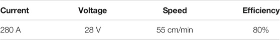
TABLE 1. Welding parameters.
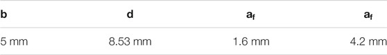
TABLE 2. Heat source parameters.
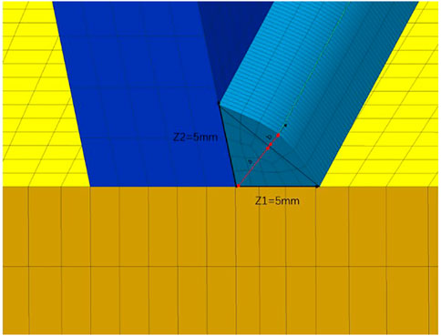
FIGURE 3. Fillet geometry dimension.

TABLE 3. Fillet geometry.
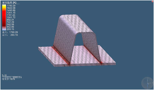
FIGURE 4. Model of temperature field.
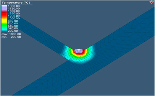
FIGURE 5. Melting pool of the model.
The welding lasted for around 2,000 s. After that, cooling was carried out until the temperature dropped to 20°C. The heat source plays a significant role in the welding process. The heat source parameters were configured based on the o design drawings of the Hong Kong-Zhuhai-Macao Bridge. Considering the different plate sizes, the authors split the simulation data into nine groups. The heat source parameters employed in welding analysis are as follows: current = 280 A, voltage = 28 V, welding speed = 55 cm/min, and efficiency = 80%. The welding models share the same material parameters and heat source parameters, but differ in geometry. In addition, the geometric parameters were properly adjusted to create a realistic heat flow through the plate surface and the melting pool.
The multiple models (Table 4) were designed to reflect how the residual stress distribution varies with thicknesses. As shown in Figure 6, there were weld lines along with the weld bead in two directions. The welding proceeded from the left to the right. Although the residual stresses were mainly distributed in the longitudinal direction, the stresses in other directions cannot be ignored during the natural frequencies analysis.
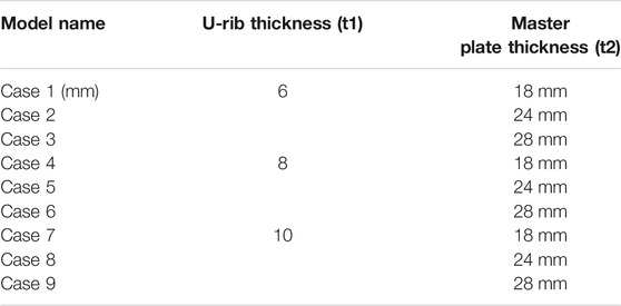
TABLE 4. Welding models.
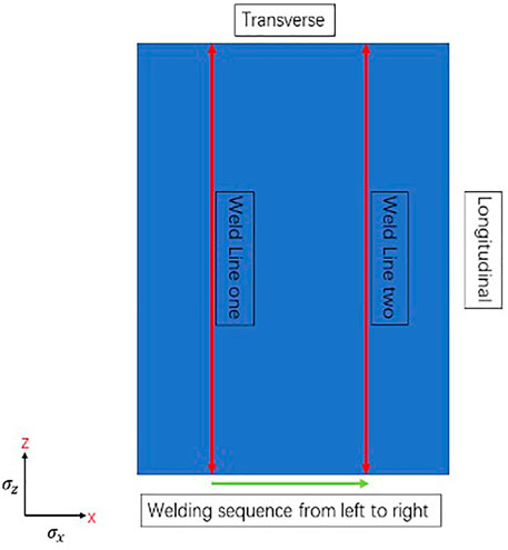
FIGURE 6. Top view of weld lines.
The residual stress distribution was examined in two directions:
It can be observed from Figures 7–12 that the residual stresses in Cases 1, 4, and 7 (master plate thickness = 18 mm) were greater than those in other cases. In other words, the compressive residual stress is negatively correlated with master plate thickness. Apparently, the residual stress was not very much affected by the changing thickness of the master plate. In Figures 10–12, the positive stress was almost twice that of the negative stress in the same position of the master plate; the stress
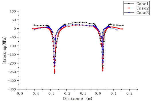
FIGURE 7. Residual stress
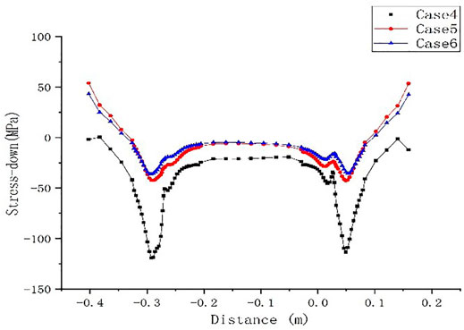
FIGURE 8. Residual stress
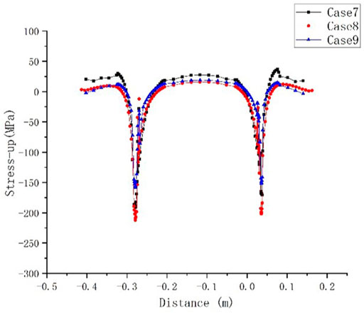
FIGURE 9. Residual stress
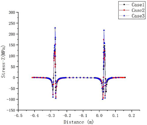
FIGURE 10. Residual stress

FIGURE 11. Residual stress
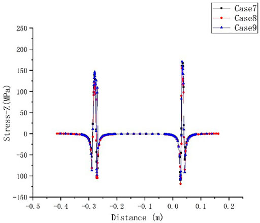
FIGURE 12. Residual stress
The simulation reveals that the stress near the weld line changed rapidly in a very narrow range. The variation of residual stress should not be ignored, during the prediction of natural frequencies. Based on the simulation results, the residual stress curve was fitted, and used to initialize the shell elements for analysis. The fitting curve of residual stress is supposed to generate a standard formula. It would be very convenient to take initial stress by the standard formula in subsequent analysis of natural frequencies.
To further analyze with the residual stresses, a half model was selected for curve fitting, in which the U-rib is 6 mm thick, and the master plate is 18 mm thick. The curves were fitted with a cubic polynomial function, and the correlation coefficient surpassed 0.9. The fitting results are illustrated in Figures 13, 14.
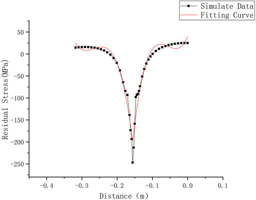
FIGURE13. Fitting curve of residual stress
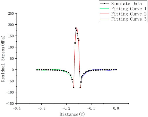
FIGURE 14. Fitting curve of residual stress
A,B,C,D is the coefficient of polynomial, which is determined by fitting curves.
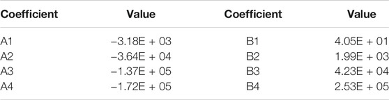
TABLE 5. Coefficient values for
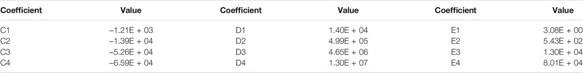
TABLE 6. Coefficient values for
The first and second equations can be expressed as:
The residual stress distribution at each thickness of the master plate can be derived with the equation parameters. Then, the residual stresses can be applied to the calculation model using the fitting curve.
For analyzing the effect of residual stress, a three-dimensional thermodynamic finite element model is extracted through the SIMFACT welding model. Six residual stress parameters, corresponding to s11, s22, s33, s12, s23, s13, respectively, are extracted and applied to the U-rib stiffened plate model simulated with shell 181. s11, s22, s33 represent the normal stresses in X,Y,Z direction and s12, s23, s13 represent the in-plane stresses in shell elements.
Since the plates are modeled by shell elements, only three parameters s11, s22, and s12 are applied to correctly simulate the analysis of the shell 181 elements. the analysis of the residual stress field in three directions considers the vibration model analysis caused by the initial stress field. Two boundary conditions have been compared in our dynamic analysis. In fixed boundary conditions, both sides of the edges have been locked in all directions. (The displacement x, y, z = 0 and rotation Ux, Uy, Uz = 0) In simply supported conditions, the displacement x, y = 0 and rotation Uy, Uz = 0. The displacement z and rotation Ux are not constrained in simply supported conditions.
In order to apply residual stress more easily, we can apply it in a piecewise function. The range of piecewise function is determined by the specific welding times and welding positions. The same structure size of welding plates (including the mother plate and stiffened plate) will generate a specific same trend fitting curve sample. We can find the fitting curve sample of the corresponding structure size and use the fitted piecewise function to apply for the actual mother plate. When actual structure size distance is measured, we put measured distances into the corresponding curve sample to predict the residual stress without using the physical experiment to measure the results.
To verify the accuracy of the finite-element model of the plate and shell, the rectangular-rib stiffened plate in H.A.Xu’s work (Xu et al., 2010) was selected as a comparison. According to the parameters of that stiffened plate, two stiffeners were set separately in the longitudinal and lateral directions. The finite-element model of the stiffened plate was built with shell 181 elements. In Abaqus, the residual stress can be applied as initial state stress in the predefined field. The dimensionless frequency parameters in work H.A. Xu’s (Xu et al., 2010) were converted into frequency values, and compared with the values calculated by the Abaqus model. The comparison shows that the initial stress condition affects the model analysis of stiffened plates. Drawing on the literature (Xu et al., 2010; Gao et al., 2014), the initial stress condition also affects the natural frequencies of the U-rib stiffened plate. Tables 7, 8 compare the residual stresses under two types of boundary conditions. The first 10 frequencies were selected for comparative analysis and the first four mode shapes were depicted.
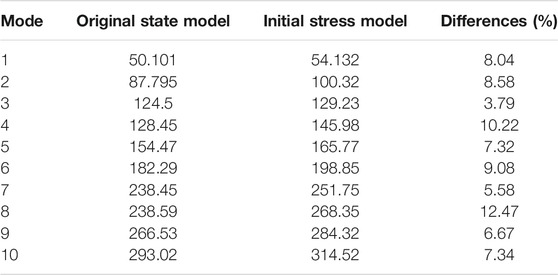
TABLE 7. Natural frequencies with fixed boundary conditions (Hz).
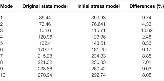
TABLE 8. Natural frequencies with simply supported conditions (Hz).
Tables 7 and 8 show that the stiffened plate had slightly lower natural frequencies under fixed boundary conditions than under simply supported conditions. When the initial stresses were considered, the natural frequencies of the stiffened plate under fixed boundary conditions was approximately 4–10% lower than those of the stiffened plate under simply supported conditions. This effect was so obvious that the initial stresses cannot be neglected for simply supported boundary conditions and fixed boundary conditions. The above results indicate that the effect of initial stresses on the natural frequencies of stiffened plates depends on actual conditions.
This paper intends to numerically analyze the natural frequencies of a stiffened plate with initial stresses. After obtaining all the calculation results from the welding process, the authors built a shell model in Abaqus to analyze the natural frequencies of stiffened plates. The effect of residual stresses was fully considered in the shell model-based simulation. Through the research, the following conclusions were drawn:
1) The results of the thermal simulation and shell models are consistent with the findings in the literature. This means the thermal simulation and shell model in Abaqus are feasible and reliable tools for vibration analysis of stiffened plates.
2) The analysis of residual stress distribution shows that the residual stress varied clearly with the thicknesses of the master plate. As the plate became thinner, the absolute value of residual stress increased, especially in the welding bead. It also means the peak residual stresses in the U-rib changes rapidly with thickness.
3) The residual stress had an obvious effect on natural frequencies of stiffened plates under simply supported conditions and fixed supported condition. The effect of initial stresses on the natural frequencies of stiffened plates should be considered according to actual conditions.
The original contributions presented in the study are included in the article/Supplementary Material, further inquiries can be directed to the corresponding author.
LC: review and editing, Software TW: original draft preparation, methodology JP: Project administration, supervision NM: Validation, supervision RW: Funding acquisition, validation.
This study was supported by the National Natural Science Foundation of China (Grant No. 51778241), Guangdong Basic and Applied Basic Research Foundation (Grant No. 2020A1515011307, 2021A1515012405, 2021B1212040003) and the Science Foundation of State key Lab of Subtropical Building Science, South China University of Technology (Grant No. 2016KA03).
The authors declare that the research was conducted in the absence of any commercial or financial relationships that could be construed as a potential conflict of interest.
All claims expressed in this article are solely those of the authors and do not necessarily represent those of their affiliated organizations, or those of the publisher, the editors, and the reviewers. Any product that may be evaluated in this article, or claim that may be made by its manufacturer, is not guaranteed or endorsed by the publisher.
Ballestra, A., Somà, A., and Pavanello, R. (2008). Experimental-Numerical Comparison of the Cantilever MEMS Frequency Shift in Presence of a Residual Stress Gradient. Sensors 8, 767–783. doi:10.3390/s8020767
Cui, C., Bu, Y. Z., and Li, J., (2018b). Distribution Characteristics of Welding Residual Stress at U Deck-To-Rib Connection Detail of Steel Box Girder (In Chinese). J. Southwest Jiaotong Univ. 53, 260–265. doi:10.3969/j.issn.0258-2724.2018.02.006
Cui, C., Zhang, Q., Luo, Y., Hao, H., and Li, J. (2018a). Fatigue Reliability Evaluation of Deck-To-Rib Welded Joints in OSD Considering Stochastic Traffic Load and Welding Residual Stress. Int. J. Fatigue 111, 151–160. doi:10.1016/j.ijfatigue.2018.02.021
Das, D., Das, A. K., Pratihar, D. K., and Roy, G. G. (2020). Prediction of Residual Stress in Electron Beam Welding of Stainless Steel from Process Parameters and Natural Frequency of Vibrations Using Machine-Learning Algorithms. Proc. Inst. Mech. Eng. C: J. Mech. Eng. Sci. 235 (11), 0954406220950343. doi:10.1177/0954406220950343
Das, D., Pratihar, D. K., and Roy, G. G. (2020). Establishing a Correlation between Residual Stress and Natural Frequency of Vibration for Electron Beam Butt Weld of AISI 304 Stainless Steel. Arab J. Sci. Eng. 45, 5769–5781. doi:10.1007/s13369-020-04560-0
Deng, D., and Murakawa, H. (2006). Numerical Simulation of Temperature Field and Residual Stress in Multi-Pass Welds in Stainless Steel Pipe and Comparison with Experimental Measurements. Comput. Mater. Sci. 37, 269–277. doi:10.1016/j.commatsci.2005.07.007
El-Axir, M. H. (2002). A Method of Modeling Residual Stress Distribution in Turning for Different Materials. Int. J. Machine Tools Manufacture 42, 1055–1063. doi:10.1016/s0890-6955(02)00031-7
Fujikubo, M., and Yao, T. (1999). Elastic Local Buckling Strength of Stiffened Plate Considering Plate/stiffener Interaction and Welding Residual Stress. Mar. Structures 12, 543–564. doi:10.1016/s0951-8339(99)00032-5
Gadallah, R., Osawa, N., Tanaka, S., and Tsutsumi, S. (2018). A Novel Approach to Evaluate Mixed-Mode SIFs for a Through-Thickness Crack in a Welding Residual Stress Field Using an Effective Welding Simulation Method. Eng. Fracture Mech. 197, 48–65. doi:10.1016/j.engfracmech.2018.04.040
Gannon, L., Liu, Y., Pegg, N., and Smith, M. (2010). Effect of Welding Sequence on Residual Stress and Distortion in Flat-Bar Stiffened Plates. Mar. Structures 23, 385–404. doi:10.1016/j.marstruc.2010.05.002
Gao, Y. Y., Tang, G., and Wan, W. (2014). Natural Frequencies Calculation of a Quadrate Thin Plate with Welding Residual Stress (In Chinese). J. Vibration Shock 33, 165–167. doi:10.13465/j.cnki.jvs.2014.09.030
Goldak, J., Chakravarti, A., and Bibby, M. (1984). A New Finite Element Model for Welding Heat Sources. Metall. Trans. B 15. doi:10.1007/bf02667333
Jiang, W., Chen, W., Woo, W., Tu, S.-T., Zhang, X.-C., and Em, V. (2018). Effects of Low-Temperature Transformation and Transformation-Induced Plasticity on weld Residual Stresses: Numerical Study and Neutron Diffraction Measurement. Mater. Des. 147, 65–79. doi:10.1016/j.matdes.2018.03.032
Lieven, N. A. J., and Greening, P. (2001). Effect of Experimental Pre-stress and Residual Stress on Modal Behaviour. Philosophical Trans. R. Soc. Lond. Ser. A: Math. Phys. Eng. Sci. 359, 97–111. doi:10.1098/rsta.2000.0715
Lin, S., and Yang, N. (2014). Numerical Simulation of Residual Stresses on Butt-weld of Thick Steel Plate (In Chinese). J. Beijing Jiaotong Univ. 38, 107–111. doi:10.11860/j.issn.1673-0291.2014.01.020
Ohashi, H., Yoda, T., and Higuchi, K. (1996). Initial Imperfection Data and Evaluation of Compressive Strength of Orthotropic Steel Deck for Long-Span Cable-stayed Bridges. Doboku Gakkai Ronbunshu 1996, 55–64. doi:10.2208/jscej.1996.549_55
Olfatnia, M., Xu, T., Ong, L. S., and Miao, J. (2010). Investigation of Residual Stress and its Effects on the Vibrational Characteristics of the Piezoelectric-Based Multilayered Micro Diaphragm. J. Micromechanics Microengineering 20.015007 doi:10.1088/0960-1317/20/1/015007
Qiang, B., Li, Y., Yao, C., Wang, X., and Gu, Y. (2018). Through-thickness Distribution of Residual Stresses in Q345qD Butt-Welded Steel Plates. J. Mater. Process. Technology 251, 54–64. doi:10.1016/j.jmatprotec.2017.08.001
Rikken, M., Pijpers, R., Slot, H., and Maljaars, J. (2018). A Combined Experimental and Numerical Examination of Welding Residual Stresses. J. Mater. Process. Technology 261, 98–106. doi:10.1016/j.jmatprotec.2018.06.004
Salerno, G., Bennett, C., Sun, W., Becker, A., Palumbo, N., Kelleher, J., et al. (2018). On the Interaction between Welding Residual Stresses: A Numerical and Experimental Investigation. Int. J. Mech. Sci. 144, 654–667. doi:10.1016/j.ijmecsci.2018.04.055
Saunders, N., Guo, U. K. Z., Li, X., Miodownik, A. P., and Schillé, J.-P. (2003). Using JMatPro to Model Materials Properties and Behavior. Jom 55, 60–65. doi:10.1007/s11837-003-0013-2
Ueda, Y., and Yamakawa, T. (1971). Analysis of thermal Elastic-Plastic Stress and Strain during Welding by Finite Element Method. J. Jpn. welding Soc. Trans. 42, 567–577.
Wang, K. F., and Wang, B. L. (2012). Effects of Residual Surface Stress and Surface Elasticity on the Nonlinear Free Vibration of Nanoscale Plates. J. Appl. Phys. 112. doi:10.1063/1.4733345
Wu, C., and Kim, J.-W. (2018). Analysis of Welding Residual Stress Formation Behavior during Circumferential TIG Welding of a Pipe. Thin-Walled Structures 132, 421–430. doi:10.1016/j.tws.2018.09.020
Wu, F. (1999). Natural Frequencies of Composite Plates with Tailored thermal Residual Stresses. Int. J. Sol. Structures 36, 3517–3539. doi:10.1016/S0020-7683(98)00154-1
Xu, H., Du, J., and Li, W. L. (2010). Vibrations of Rectangular Plates Reinforced by Any Number of Beams of Arbitrary Lengths and Placement Angles. J. Sound Vibration 329, 3759–3779. doi:10.1016/j.jsv.2010.03.023
Yang, Z., Huang, Y., Liu, A., Fu, J., and Wu, D. (2019). Nonlinear In-Plane Buckling of Fixed Shallow Functionally Graded Graphene Reinforced Composite Arches Subjected to Mechanical and thermal Loading. Appl. Math. Model. 70, 315–327. doi:10.1016/j.apm.2019.01.024
Zhao, Q., and Wu, C. (2012b). A Simplified Calculation Method of Welding Residual Stress of U-Rib Stiffened Plates (In Chinese). Eng. Mech. 29, 170–176. doi:10.6052/j.issn.1000-4750.2010.12.0935
Zhao, Q., and Wu, C. (2012a). Numerical Analysis of Welding Residual Stress of U-Rib Stiffened Plate (In Chinese). Eng. Mech. 29, 262–268. doi:10.6052/j.issn.1000-4750.2010.12.0936
Keywords: steel box girder, U-rib stiffened plate, welding residual stress, numerical simulation, natural frequencies
Citation: Chen L, Wang T, Pan J, Ma N and Wang R (2022) Welding Residual Stress Distribution of U-Rib Stiffened Plates of Steel Box Girders and its Influence on Structural Natural Frequencies. Front. Mater. 9:876111. doi: 10.3389/fmats.2022.876111
Received: 15 February 2022; Accepted: 07 March 2022;
Published: 28 March 2022.
Edited by:
Tianyu Xie, RMIT University, AustraliaReviewed by:
Chao Dou, Beijing Jiaotong University, ChinaCopyright © 2022 Chen, Wang, Pan, Ma and Wang. This is an open-access article distributed under the terms of the Creative Commons Attribution License (CC BY). The use, distribution or reproduction in other forums is permitted, provided the original author(s) and the copyright owner(s) are credited and that the original publication in this journal is cited, in accordance with accepted academic practice. No use, distribution or reproduction is permitted which does not comply with these terms.
*Correspondence: Jianrong Pan, Y3RqcnBhbkBzY3V0LmVkdS5jbg==
Disclaimer: All claims expressed in this article are solely those of the authors and do not necessarily represent those of their affiliated organizations, or those of the publisher, the editors and the reviewers. Any product that may be evaluated in this article or claim that may be made by its manufacturer is not guaranteed or endorsed by the publisher.
Research integrity at Frontiers
Learn more about the work of our research integrity team to safeguard the quality of each article we publish.