
94% of researchers rate our articles as excellent or good
Learn more about the work of our research integrity team to safeguard the quality of each article we publish.
Find out more
ORIGINAL RESEARCH article
Front. Mater., 25 April 2022
Sec. Smart Materials
Volume 9 - 2022 | https://doi.org/10.3389/fmats.2022.875787
 Rusdi Mat Song1
 Saiful Amri Mazlan1*
 Norhasnidawani Johari1
 Fitrian Imaduddin2
 Siti Aishah Abdul Aziz1
 Abdul Yasser Abd Fatah3
 U. Ubaidillah2*
This study proposes the design and fabrication of a natural rubber-based magnetorheological elastomer (NR-MRE) engine mount as a new device in absorbing the vibration originated from the automotive engine. The conceptual design was performed through a simulation process by Finite Element Method Magnetics to analyze the magnetic field distribution. The simulation result had indicated that the device was capable of generating an equivalent magnetic field density of 0.31 T at the effective area. The MRE was prepared by utilizing 60 wt% of carbonyl iron particles (CIPs), and the cavity was filled by compression molding. The MRE compound was tested based on its basic mechanical properties, while the MRE engine mounts were tested under a static compression load at off- and on-state conditions. It was observed that the compound possessed a good tensile strength for a load bearer matrix with an average of 12.65 MPa. Subsequently, the results of the static compression load had showed that the MRE engine mounts recorded an increase of 12% in the force generated as compared to conventional engine mounts at an off-state condition. Meanwhile, at an on-state condition of 2.4 A, the MRE engine mounts recorded an increase in the force generated with 106%. The study has demonstrated that the proposed device can be one of the potential candidates for vibration control applications due to its stiffness controllability.
The engine mount is a mechanical device used in holding an engine with the frame or chassis. It consists of an elastomer rubber placed in between the metal casing and center core. The functions are to support the engine mass and to absorb and isolate the vibration occurring in the engine, thus reducing it from transferring to the rest of the vehicle’s structure (Yu et al., 2001; Ooi and Ripin, 2011). To date, rubber has been widely used as a material in the engine mounting system (Wang and Kari, 2019) due to the low damping properties and elastic stiffness in absorbing the vibration. In order to fit the desired applications, few types of engine mounts have been designed and developed until today, such as the elastomeric mount, hydraulic mount, semi-active mount, and active mount (Yang et al., 2019). The elastomeric engine mount or conventional engine mount utilized the conventional rubber compound, having uniform and rigid mechanical properties in which the vibration control and attenuation are generally effective at narrow frequency ranges (Jung et al., 2010; Xu et al., 2010; Ubaidillah et al., 2015) and are unable to operate satisfactorily in a wide range of conditions. While the hydraulic engine mount, consisting of the usage of liquid medium (Shangguan, 2009), greatly increased damping at low frequency, the degraded isolation performance is at high frequency (Yu et al., 2001) and is limited in durability (Jeong et al., 2013). Nowadays, moving out of the boundary of passive type device utilization, active versions of engine mounting systems have drawn the awareness of vibration absorption designers and researchers. An active engine mount, which consists of an active force generator and controller, possesses superior performance not only in the vibration reduction ability but also for its fast response (Swanson, 1993; Yu et al., 2001; Lerner and Cunefare, 2008). However, it is also reported that such devices have several limitations such as higher system cost and heavier weight (Sun et al., 2018; Soliman and Kaldas, 2019), having system complexity and decreasing its stability (Th et al., 1985; Kela and Vähäoja, 2009). It is for these reasons that the semi-active engine mount such as MRE engine mounts have attracted the attention of current researchers due to its simplicity in design yet being effective (Liao et al., 2011; Hoang et al., 2013; Sun et al., 2015, 2018).
The MRE engine mount is a device in which the elastomeric rubber part was replaced with an MRE sample that consists of micron-size magnetizable particles suspended in its matrix material. In the presence of a magnetic field, this type of material exhibits tunable stiffness, which has an effect on its storage and loss modulus (Nam et al., 2020). The end purpose of the device’s performance development is to fabricate an MRE engine mount with a good MR effect, low damping ratio, and a good tensile and fatigue strength (Burgaz and Goksuzoglu, 2020). The good MR effect is denoted by the proportionate change in storage modulus (G′) toward the applied strength of the magnetic field, while a good tensile strength is denoted by a high tensile strength of the matrix material used such as the natural rubber (NR). Recently, numbers of semi-active MRE engine mounts have been proposed and tested for their performance using various types of device design and configuration (Albanese and Cunefare, 2003; Hoang et al., 2011; Kavlicoglu et al., 2011; Xin et al., 2017). Different configurations of the proposed device vary in fulfilling the requirement of the device fundamental aspect and are generally divided into three criteria, which are the matrix material selection, shape, and size of the compound used together with the employed coil configuration. Detailed research studies have been carried out as well, using a series of numerical models due to the viscoelastic characteristic of the material which exhibits nonlinear properties with the displacement amplitudes and frequencies under magnetic field stimuli (Nguyen et al., 2018; Yu et al., 2019). Understanding and modeling the mechanical behaviors of MREs under different magnetic field strengths are necessary to design an appropriate MRE-based semi-active control device (Nguyen et al., 2019).
In terms of device configuration involving the matrix material, silicone rubber has been widely utilized as a medium in MRE fabrication due to its easy sample preparation since it can be easily processed during compounding and retains various enhancement capabilities such as high field-induced relative stiffness (Shenoy et al., 2020). Deng et al. (2006) has reported an increase of 147% in terms of relative frequency for the devices utilizing silicone rubber, while Liao et al. (2011) revealed a device capability in the resonant frequency increment from 11 to 18 Hz. Meanwhile, Sun et al. (2014) also reported on a natural frequency shift from 37 to 67 Hz, and Dargahi et al. (2019) revealed an astonishing 1672% increase of storage modulus for vibration control devices. In general, all of these reported performance materials are capable to be applied for the potentially relevant engineering applications. However, there were evidences that proved this type of soft matrix was not suitable to be used in the load-bearing device due to its low strength and fatigue life (Fuchs et al., 2007; Qiao et al., 2012; Zhu et al., 2012). Natural rubber, on the other hand, offers high elasticity, tensile and tear strength, excellent wearability, abrasive resistance, easy availability, and low cost (Schaefer, 2002; Jung et al., 2015; Belluci et al., 2016; Fan et al., 2018) and is also capable to sustain a wide range of deformation and flexibility in industrial applications (Alam et al., 2020).
Meanwhile, the second criterion of the device structure is characterized by the geometrical shape and size of the prepared matrix compound. Many research studies generally focus on small and thin samples, which geometrically include square, rectangular, and circular or round pieces. Moreover, most of the study basically focused on the use of thick MRE samples in the range of 3–10 mm due to their easy laboratory sample preparation for performing the test. As such, Ginder et al. (2001) explored a tuneable device performance using an MRE material having the size of 60 mm in diameter with 2 mm thickness. In another study, Jeong et al. (2013) proposed a differential mount using a rectangular MRE sample with an initial size of 30 × 12 mm2 with 5 mm thickness. Xin et al. (2017) proposed a powertrain mount utilizing a circular cylindrical MRE with 68 and 56 mm of the outer and inner diameter, respectively, and 10 mm thickness. Zhang and Ren (2019) designed an automobile vibration-reducing device using MRE samples having thickness of 3 and 6 mm. However, limited study was observed in the study based on the actual size of the rubber composite or MRE used in the engine mount device. Therefore, it is interesting to observe the behavior and the performance of the industrial scale MRE-based engine mount with an industrial scale size of the MRE sample fabricated using the industry’s compression molding machine.
The last criterion of the device structure is characterized by the device design including coil configuration for an optimum magnetic field distribution throughout the device, especially at the MRE effective area. Furthermore, coil configuration is identified by its location, placed either internally or externally, and also by the number of the coil used, either single or multicoil. Albanese and Cunefare (2003) discussed a semi-active absorber device which consisted of MR silicone of 0.5 cm in length in between the steel loops of 3.6 cm in length, wound with a magnet wire as the coil. They found that the size of the device was seven times bigger than the MR composite and was capable of shifting the initial natural frequency of 45 up to 183 Hz. Due to its small size, the device was suitable to be used in constraint space. Kavlicoglu et al. (2011) reported an MRE mount consisting of four MRE layers, each with 12.7 mm thickness and two electromagnetic coils sandwiched in between the mounting plates and secured by epoxy glue. The generated magnetic field from the coils directly penetrated the MRE layers toward the outer mounting plates and thus gained the maximum stiffness change under magnetic fields up to 0.4 T, resulting in 90% change of the compression stiffness. Meanwhile, Hoang et al. (2011) designed a vibration absorption device consisting of an MRE material placed in between an inner and outer cylinder, excited by the three external magnetic coils, with each coil capable of generating a magnetic field up to 0.3 T. Xin et al. (2017) proposed a powertrain mount device, composed of a semi-active vibration absorption unit, which utilized an O-ring type MRE with an outer diameter of 68 mm, inner diameter of 56 mm, and thickness of 10 mm. The device utilized a single internal magnetic coil covered with high magnetic permeability structures made from pure iron to ensure a closed property of the magnetic circuit and increase the magnetic flux intensity through the MRE. Such a design prevented unnecessary field leakage, thus capable of generating a high magnetic field intensity up to 0.68 T with a supplied current of 2 A. In general, the main and critical criteria in the reliable device design and coil configuration lie in the sufficient distribution of the magnetic field in which the circulation of the magnetic flux reaches throughout the MRE area (Li et al., 2020). Moreover, the design with a closed loop property of the magnetic circulation also plays an important role in avoiding unnecessary field leakage.
From these studies, the results demonstrated the possibility and potential of the proposed semi-active MRE engine mounts in absorbing and isolating the vibration. However, most of the studies focused on the device utilizing the lab-scale soft matrix compound for high performance results and ease of fabrication processes. Therefore, this study contributes to the MRE property characterization of the material carried out by the static test, representing the elastomer as “high elastic” rather than the viscoelastic nature which is carried out by dynamic tests (Shenoy et al., 2020), in evaluating an industrial scale device of an engine mount utilizing an appropriate load bearer matrix carrier, which is also fabricated industrially to be tested under magnetic field stimuli. The selection of materials together with the carbonyl iron particle (CIP) content is considered in order to obtain an optimum device design with high magnetic field strength throughout the effective area. The device’s conceptual design and the magnetic distribution analysis are being validated by Finite Element Method Magnetics (FEMM), and such an approach of validating the magnetic distributions using a simulation method is being carried out by most of the eminent researchers in this field (Xin et al., 2017; Samal et al., 2020; Shenoy et al., 2020; Huang et al., 2021). Future works will focus in the dynamic method together with the control system evaluation.
The industrial fabricated engine mount possesses a cylindrical shape with an external casing diameter of 68 mm and a center core diameter of 12 mm with the height of 40 mm. The external casing and the center core are separated by the MRE compound. The center core is attached to the vehicle’s engine by means of a bolted shaft, while the external casing is attached to the vehicle’s frame via the structure casing, thus holding the engine at its position and supporting the engine’s weight. As the engine is in operation and subjected to vibration, the MRE compound will isolate and attenuate the vibration from transferring to the rest of the vehicle’s structure. Subjected under the industrial product specification is the engine mount having the maximum amplitude of 7 mm and maximum load capacity of 2 kN. Figure 1A represents the cross-sectional area of the entire proposed structure of the MRE engine mount. The conceptual design structure consists of an outermost cylindrical housing, covered with two cover plates, in which each plate is located at the top and bottom of the structure, a bobbin core, an electromagnetic coil winding around the bobbin, and finally the cylindrical MRE engine mount was press-fitted at the very center of the design to ensure its rigidity. Figure 1B shows a schematic representation of the entire structure.
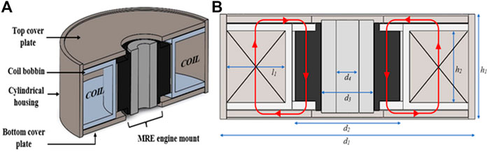
FIGURE 1. Conceptual design (A) 3D cross-sectional drawing of the entire structure of the MRE engine mount; (B) Schematic representation of the entire structure of the MRE engine mount.
Because of the current being supplied to the electromagnetic coil, the magnetic fluxes were generated and circulated throughout the structure, and the flows were then directed toward the MRE area, as shown by the red arrows in Figure 1B, representing the magnetic passage. As the ranges of the magnetic field excitation are being imposed on the engine mount, the stiffness of the MRE could be tuned by adapting the supplied current, and simultaneously, the vibration of the engine mounting system could be attenuated correspondingly. Further analysis of the magnetic distribution in the results and discussion section represented by Figure 9A indicates that the magnetic flux distribution formed a closed loop path, and thus, the magnetic leakage was optimally prevented. The structural parameters of the design are listed in Table 1.
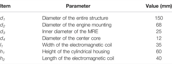
TABLE 1. Structural parameter of the MRE engine mount structure.
The diameter of the entire structure d1 represents the overall diameter measurements for the cylindrical housing, while h1 represents the height or the width of the structure consisting of the top and bottom cover plates together with the height of the electromagnetic coil. As such, the entire structure is having a general size of 150 mm × 60 mm. The design concept has been modified by using an external magnetic coil instead of an internal magnetic coil, in which the original work of the vibration absorber utilizing the internal coil for the powertrain mount system was carried out by Xin et al. (2017). By using an external magnetic coil, the simulation result of the magnetic flux distribution in Figure 9A had shown that the full coverage of the magnetic flux could be provided throughout the area, which was from the top side of the MRE effective area toward the bottom side. The dimensions of the coil are represented by l1 and h2, which are the width and the length of the coil area, respectively. In this study, a 24 SWG-coated copper wire with the diameter of 0.6 mm has been selected to generate the magnetic field in the MRE engine mount. A total number of 3,500 turns were wound around the coil, together with 56 layers, with each layer having 63 turns of the copper wire.
The fabrication of the entire structure consisted of three major stages, which were the MRE compound preparation, electromagnetic coil designing and fabrication, and finally the fabrication of the MRE engine mount. In addition, the experimental setup and procedures were then explained in the following section, which include several tests comprising the MRE compound test and the engine mount test in terms of the static compression in evaluating the device performance.
The natural rubber-based MRE has been introduced as the matrix material for the engine mount device. In this study, the raw material of natural rubber was supplied by Titron Rubber Industries (M) Sdn Bhd, Banting, Malaysia. Other compositions such as zinc oxide (ZnO), plasticizers, and additives were provided by the same company. In addition, carbonyl iron particles (CIPs) of OM type were purchased from BASF, Germany, having an average diameter of 6 µm with a density of 7.8 g/cm3, and were used as magnetic particles. The detailed composition, together with their function, of the MRE samples is tabulated in Table 2.
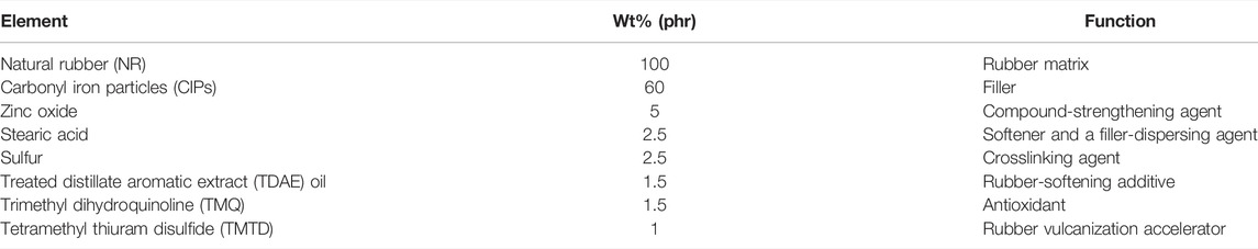
TABLE 2. Composition of the MRE.
The fabrication of the MRE compound consisted of composition mixing and the preforming configuration process. In this work, an industrial double-roll mill machine was used to mix the compound under a controlled temperature of 75°C. The two rollers spun in different directions with adjustable roll gaps as the machine ran, subjecting the NR in between the rolls to a high extrusion pressure and shear force. The molecular chains of the NR were broken down by continually revolving the rolls, and the NR gradually lost its elasticity and acquired a viscous state, signified by a sticky reaction on the roller surface. Then, the cross linkers and processing aids, the CIPs, and plasticizers were added into the new form of viscous natural rubber. The mixing process was further continued for about 15 min in order to achieve a good incorporation and dispersion of the added components by observing the solid compound without adhesion on the roller surface and homogenous color compound. The resulting MRE compound was finally produced into a sheet molding compound to be used in the molding process.
In general, the engine mount consisted of a center core and engine mount casing, bonded by an elastomeric rubber, which in this case is the fabricated MRE compound. The machine used in this process was the LIN CHENG IRH-S3 molding machine. The molding process started with a mold cavity being preheated. Next, the center core and engine mount casing were placed at the mold cavity, and the MRE sheet was being cut into smaller pieces to be inserted inside the empty space between the center core and the engine mount casing. The mold was then being securely closed and brought into the compression molding machine where heat and pressure were being applied gradually. The curing temperature was set at 160°C, and after 30 min of curing time, the mold was then being cooled, and the part was removed and stored under room temperature for 24 h before the testing process. The fabrication process of the engine mount was being assisted and monitored by HML Auto Industries Sdn Bhd in Jeram, Selangor, Malaysia.
The fabrication process of the electromagnetic coil commenced with the fabrication of coil bobbin. The process was carried out using a conventional lathe machine model OPTIturn D330 Maschinen, as shown in Figure 2A. The dry cutting process was carried out using a carbide cutter with a cutting speed of 120 m/min. The type of material selected for the fabrication of the magnetic coil bobbin was aluminum with an initial solid cylinder dimension of 152 mm (diameter) by 80 mm (length). The end product of the coil bobbin shown in Figure 2B consists of a through hole in the middle to fix in the engine mount and a groove to place the magnetic coil copper wire. Finally, a copper wire type 24 SWG with 0.6 mm diameter size was used in winding the electromagnetic coil inside the fabricated groove of the cylindrical coil bobbin, as shown in Figure 2C. The total number of coil’s turns on the cylindrical bobbin was 3,500 turns, and the total electric resistance was 81 Ω. The total number of coil turns was determined based on the total area of the cylindrical coil bobbin, the diameter of the copper wire, and the optimum magnetic field strength distributed in the MRE effective area.
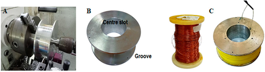
FIGURE 2. Fabrication of the electromagnetic coil (A) Coil bobbin machining process, (B) Machined part of the coil bobbin, and (C) End product of the electromagnetic coil by winding the copper wire around the bobbin.
MRE dumbbell tensile test samples were cut with a die and tested using a TENSILON mechanical test machine at room temperature. The gauge length was 20 mm, while the width and thickness of the samples at this section were 5.3 and 2.3 mm, respectively. Both ends of the sample were clamped during testing. The tensile speed applied for the test was 500 mm/min. The quoted results were averaged over at least three specimens.
A universal testing machine is a common piece of equipment used for the static testing of the viscoelastic material. In this work, an electromechanical tester (MTS model E44.304) was employed to evaluate the stiffness performance under static compression of the MRE engine mounts, as designed and fabricated previously. The tests were carried out for both off- and on-state conditions, which referred to the absence and presence of the magnetic field, respectively. An automatic voltage regulator model TDGC2-1KVA was used to supply a range of current to the electromagnetic coil. The design structure is vertically set up during testing, and the testing mode is subjected to the compression mode, as shown in Figure 3. Between the load cell and the test jig, the full construction of the MRE engine mount was installed. As the vertical load was being applied, the engine mount was held fixed at the testing jig by using a solid shaft through a hole of the engine mount, causing the displacement of the elastomer of the mount. The load cell used to measure the force applied and the displacement and the data were then recorded by the computer. The testing procedure is shown in the following Table 3.
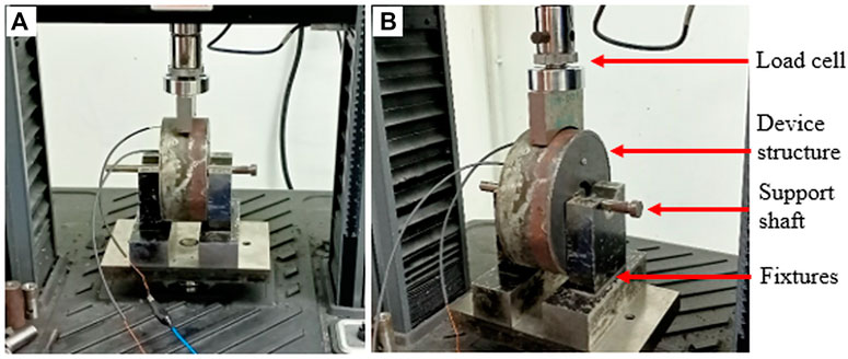
FIGURE 3. Experimental setup of the static compression test from (A) front view and (B) side view.
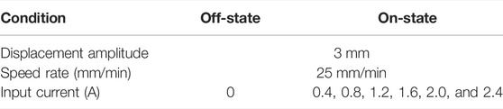
TABLE 3. Static compression test procedure.
Simulation processes were carried out by FEMM to ensure the effectiveness of the magnetic circuit distribution throughout the entire structures. The selection of the suitable material type and thickness of the cover plates and cylindrical housing was also simulated to ensure high magnetic flux density throughout the MRE engine mount. FEMM had been utilized to analyze the distribution of the magnetic flux throughout the structure of the MRE engine mount. The design of the entire structures of the MRE engine mount was divided into three parts. The first part corresponded to the cylindrical coil bobbin. The second part referred to the assembly of the MRE engine mount itself consisting of the cylindrical MRE, engine mount casing, and center core, while the third part comprised a cylindrical housing together with the top and bottom cover plates. Figure 4A shows a diagram of the 2D planar and axisymmetric structure of the engine mount with the external coil labeled with associate sections, while Figure 4B demonstrates a graphical postprocessing magnetic field encompassing the two-dimensional planar and axisymmetric geometries or the sections in FEMM. The color tone dictates the density plots for a quick reference in determining the flux density in various sections or parts of the model. Details of the material selection are tabulated in Table 4. The obtained B-H curve for the MRE material is significant with that observed in the study by Wahab et al. (2016), in which the magnetic flux density of the MRE material has a linear relationship with the magnetic flux density, from the application of 60 wt% of carbonyl iron particles.
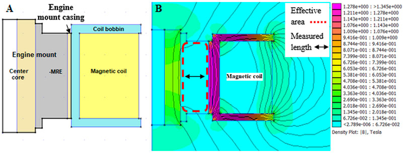
FIGURE 4. (A) 2D axisymmetric planar diagram of the engine mount with an external coil; (B) Distribution of the magnetic field throughout the device.
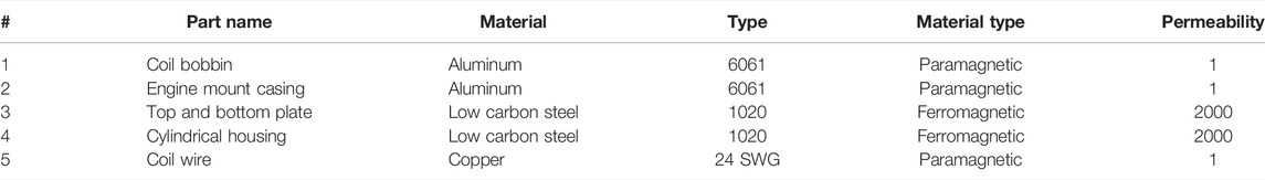
TABLE 4. Part summary of the device structure.
The distribution of magnetic flux on the bobbin material and thickness are shown in Figures 5, 6, respectively. Selection of the non-magnetic material resulted in high magnetic flux concentration at the MRE area with 0.169 T, compared to the selection of the magnetic material which is much lower. Meanwhile, various bobbin thicknesses resulted in various magnetic flux concentrations. The highest magnetic flux density was recorded for the bobbin thickness of 2 mm. However, it was not suitable to be applied in the fabrication of the bobbin because it would not be able to withstand the pressure during compression testing. Selection of the thick bobbin would cause the magnetic flux density drop much lower. Therefore, in this study, the material of non-magnetic type has been selected for the coil bobbin with the thickness of 4 mm which could generate high magnetic flux density at the effective area of the MRE.
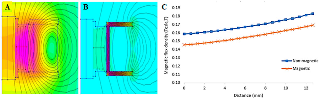
FIGURE 5. Magnetic flux distribution, (A) Non-magnetic material bobbin, (B) Magnetic material bobbin, (C) Magnetic density analysis on the bobbin material’s type.
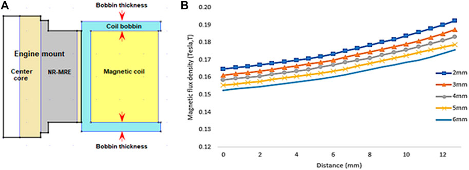
FIGURE 6. (A) Schematic representation of the coil bobbin thickness; (B) Magnetic density analysis on the coil bobbin thickness.
Figure 7 shows the distribution of the magnetic flux by using two different types of material for the engine mount casing. It can be detected from Figure 7A that with the application of the non-magnetic material as the engine mount casing, the distribution of the magnetic flux mainly focuses and generates at the MRE effective area compared to Figure 7B, whereas the magnetic flux distribution certainly concentrates on the magnetic region of the engine mount casing itself. The magnetic flux density values between the two different types of materials for the engine mount casing are shown in Figure 7C. The application of the non-magnetic material for the casing resulted in a high magnetic flux density at the effective area with an average value of 0.169 T and an astound increase of 600% flux density compared to the application of the magnetic-type material with an average value of 0.024 T. Based on this, material selection for the engine mount casing would be of non-magnetic type material, which could generate the higher magnetic flux density at the effective area.
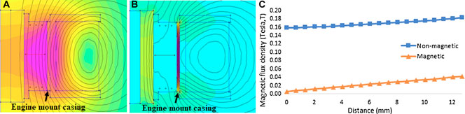
FIGURE 7. Magnetic flux distribution, (A) Non-magnetic material mount casing, (B) Magnetic material mount casing, and (C) Magnetic density analysis on the mount casing material's type.
Figure 8 illustrates the distribution of the magnetic flux on the entire device structure with and without the application of the full cover. It can be observed that the application of the full cover has resulted in the most magnetic flux distribution in the inside area, as shown in Figure 8A, compared to Figure 8B in which the magnetic flux distribution scatters at the outside area. Moreover, the application of the full cover ensured the closed property of the magnetic field circuit and increased the magnetic flux concentration through the MRE area. Figure 8C demonstrates the magnetic flux density values toward the application of the full cover. It showed that by properly covering the device with a cylindrical housing, the plates have showed high magnetic flux density at the effective area with a recorded average value of 0.31 T and an increase of 83% flux density compared to the one without the full cover, with a recorded average value of 0.169 T. Based on these results, the device would be fully covered to generate a higher magnetic flux density at the effective area.
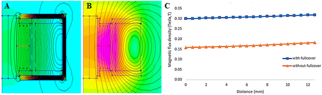
FIGURE 8. Magnetic flux distribution on device structure, (A) with full cover, (B) without full cover, and (C) Magnetic density analysis on the device structure, with and without the application of the full cover.
Figure 9A reveals the circulation of the magnetic fields throughout the entire structure after the magnetic distribution analysis of all the parts. It could be observed that most of the magnetic field circulation was concentrated inside the structure, thus avoiding much of the field leakage, and the distribution of the magnetic flux at the effective area was uniform. Figure 9B represents the plotted strength of the magnetic flux at the MRE effective area in which the measurements are taken at the middle section of the area. The magnetic flux density distribution at the effective area was uniform, with an average value of 0.31 T. Based on the simulation results, it showed that the designed structure of the MRE engine mount was capable in providing a closed property of the magnetic circuit with minimum magnetic leakage and high magnetic flux density through the effective area. As a consequence of the thorough consideration of the design of various segments, beginning with the bobbin coil material selection and progressing through the full cover of the device structure using FEMM, the results yield an overall structure of the MRE engine mount with a high magnetic flux density distribution. The details of each part are shown in the following Table 4.
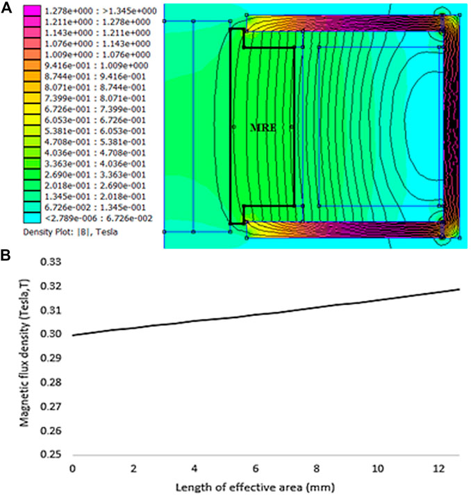
FIGURE 9. (A) Overall magnetic field circulation throughout the entire device structure and (B) Strength of the magnetic flux at the MRE effective area.
In this work, the fabricated MRE compound was being tested for its mechanical properties such as tensile strength, elongation, and hardness. The tests were carried out using the Japanese standard of JIS K6301:1995—Physical Testing Methods for Vulcanized Rubber. Table 5 shows the results by averaging from three specimens of the tests. Based on the mechanical properties of the test results, it was observed that the fabricated compound based on the natural rubber matrix possesses a high tensile strength of 12.65 MPa and high elongation at break at 590%. Moreover, the compound has a high hardness of 48 mm because the presence of the micro-sized CIPs led to having a higher surface area, contributing to a greater reinforcing effect.

TABLE 5. Mechanical performance of the MRE compound.
Figure 10A represents the graph of force and displacement for the off-state static compression tests of the engine mounts, in which the compression displacement was ranging up to 3 mm with a maximum load of 200 N. The test was carried out to observe the performance of the engine mounts upon the applied load during the off-state condition or, in other words, during the absence of the magnetic field. From the tabulated results as in Table 6, it is observed that the MRE engine mount recorded the highest maximum force of 0.982 kN, with an increment of 12% in the compression force compared to the conventional engine mount fabricated using a conventional rubber with a maximum force of 0.876 kN. The test indicated that the engine mount utilizing the MRE compound provided a superior ability in withstanding the applied load compared to the normal rubber compound. This was due to the fact that the vulcanization process of CIPs served as reinforcing fillers, forming a sort of arrangement on the polymer’s main chain, allowing for more interaction between the chains.
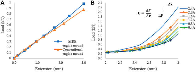
FIGURE 10. Plotted graph of force vs. displacement in the static compression tests, (A) off-state condition and (B) on-state condition.
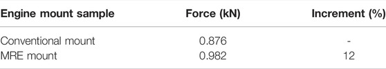
TABLE 6. Maximum force (kN) of the engine mounts.
Figure 10B represents the force and displacement of the MRE engine mount with different supplied currents. The test was performed in the presence of magnetic field in terms of supplied currents varying from 0.4 to 2.4 A. It was obvious from the graph that the force increased by increasing the supplied current. Moreover, the increment of the forces was significant as the displacement exceeded 2 mm. The divergent forces were large at 3 mm of extension, where the force generated from the MRE engine mount with 2.4 A was the highest by 106% as compared to the generated force without the supplied current (0 A). The obtained divergent forces were the field-dependent behavior that influenced the strength of the applied magnetic field, which represented the supplied current and displacement length. This is due to the dependence of the magnetic force on the distance between the magnetic particles. As the displacement exceeded 2 mm in length, the distance between the particles in a chain was minimized, and the magnetic interaction was the strongest. The result was agreed well with that observed in the study by Vatandoost et al. (2017), in which the behavior of the MRE becomes stiff with the applied magnetic field and displacement amplitude. The static stiffness of the MRE engine mount subjected under ranges of the supplied current is shown in Figure 11. The static stiffness with spring constant k describes the relation between the force and displacement of the elastomer when the speed of the component’s deformation is negligible, and it is commonly characterized by the slope of the linear region represented by the following equation:
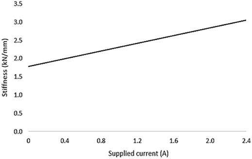
FIGURE 11. On-state static stiffness of the MRE engine mount.
Based on the figure, it shows that the stiffness of the device exhibits a linear relationship with the supplied currents. The stiffness of the engine mount increased with the increasing supplied current and has proved that the MRE was a multi-functional material in which the rheological property could dynamically be changed with respect to an external magnetic field. The increment forces showed that the stiffness of the MRE engine mount was able to tune by adapting the applied current, and simultaneously, the vibration could be attenuated correspondingly.
In this work, an industrial scale engine mount equipped with an appropriate load bearer matrix carrier was fabricated industrially and tested for the compression load performance under the influence of magnetic field stimuli. The entire structure was designed accordingly and analyzed using FEMM for an optimum magnetic flux density throughout the effective area of the MRE, where an average value of 0.31 T of the magnetic flux density was obtained. Based on the structured analysis of each part, the fabrication process was carried out. Starting with compound preparation and the test of mechanical properties, the results showed that the MRE compound held a good tensile strength and hardness of 12.65 MPa and 48, respectively. The static compression tests at off- and on-state conditions were then carried out to test the effect of the engine mount at various ranges of the supplied current. At the off-state test, the MRE engine mount recorded the highest force with 12% increment at 3 mm of extension compared to the normal engine mount utilizing a conventional rubber. While at the on-state test, the MRE engine mount showed an increase in the compression force as the current was being increased gradually up to 2.4 A. At 3 mm of extension, the force with 2.4 A was increased by 106% with the supplied current. A linear relationship of stiffness with the increasing supplied currents has demonstrated that the MRE engine mount was influenced by the presence of the magnetic field. Thus, the proposed design of the MRE engine mount can be effectively utilized in generating controllably required stiffness by tuning the applied current (magnetic density) accordingly. The necessity of the dynamic test subjected under different amplitudes and frequencies together with the control system of the proposed device is very well taken into consideration that will be undertaken as the second phase of this work.
The raw data supporting the conclusion of this article will be made available by the authors, without undue reservation.
RM: writing–original draft and investigation. SM: conceptualization, supervision, validation, and writing–review and editing. NJ: validation and editing. FI: formal analysis, methodology, validation, and writing–review and editing. SA: resources, and writing–review and editing. AA: software. UU: editing and funding.
This work was supported by the Universiti Teknologi Malaysia Prototype Research Grant (UTMPR) (Vot No. 00L46) and Universiti Teknologi Malaysia Encouragement Research Grant (Vot No. Q.K130000.2643.17J73). This work is also funded by Universitas Sebelas Maret through Hibah Kolaborasi Internasional 2022.
The authors declare that the research was conducted in the absence of any commercial or financial relationships that could be construed as a potential conflict of interest.
All claims expressed in this article are solely those of the authors and do not necessarily represent those of their affiliated organizations, or those of the publisher, the editors, and the reviewers. Any product that may be evaluated in this article, or claim that may be made by its manufacturer, is not guaranteed or endorsed by the publisher.
The authors would like to acknowledge Universiti Teknologi Malaysia for supporting this research through the provided grants and high appreciation to Titron Rubber Industries (Malaysia) Sdn. Bhd. and HML Auto Industries Sdn. Bhd. for their technical advices and facilities support. The authors are very grateful upon their eloquent contributions.
Alam, M. N., Kumar, V., Ryu, S.-R., Choi, J., and Lee, D.-J. (2020). Magnetic Response Properties of Natural-Rubber-Based Magnetorhelogical Elastomers with Different-Structured Iron Fillers. J. Magnetism Magn. Mater. 513, 167106. doi:10.1016/j.jmmm.2020.167106
Albanese, A.-M., and Cunefare, K. A. (2003). Properties of a Magnetorheological Semi Active Vibration Absorber. Smart Struct. Mater. 5052, 36–43.
Bellucci, F. S., Lobato de Almeida, F. C., Lima Nobre, M. A., Rodríguez-Pérez, M. A., Paschoalini, A. T., and Job, A. E. (2016). Magnetic Properties of Vulcanized Natural Rubber Nanocomposites as a Function of the Concentration, Size and Shape of the Magnetic Fillers. Composites B: Eng. 85, 196–206. doi:10.1016/j.compositesb.2015.09.013
Burgaz, E., and Goksuzoglu, M. (2020). Effects of Magnetic Particles and Carbon Black on Structure and Properties of Magnetorheological Elastomers. Polym. Test. 81, 106233. doi:10.1016/j.polymertesting.2019.106233
Dargahi, A., Sedaghati, R., and Rakheja, S. (2019). On the Properties of Magnetorheological Elastomers in Shear Mode: Design, Fabrication and Characterization. Composites Part B: Eng. 159, 269–283. doi:10.1016/j.compositesb.2018.09.080
Deng, H.-x., Gong, X.-l., and Wang, L.-h. (2006). Development of an Adaptive Tuned Vibration Absorber with Magnetorheological Elastomer. Smart Mater. Struct. 15, N111–N116. doi:10.1088/0964-1726/15/5/N02
Fan, L., Wang, G., Wang, W., Shi, G., Yang, F., and Rui, X. (2018). Investigations on the Properties of NH4HCO3filled Natural Rubber Based Magnetorheological Elastomers (MREs). Mater. Res. Express 5, 045307. doi:10.1088/2053-1591/aab79e
Fuchs, A., Zhang, Q., Elkins, J., Gordaninejad, F., and Evrensel, C. (2007). Development and Characterization of Magnetorheological Elastomers. J. Appl. Polym. Sci. 105, 2497–2508. doi:10.1002/app.24348
Ginder, J. M., Schlotter, W. F., Nichols, M. E., and Mi, U. S. A. (2001). Magnetorheological Elastomers in Tunable Vibration Absorbers. Smart Struct. Mater. 4331, 103–110.
Hoang, N., Zhang, N., and Du, H. (2011). An Adaptive Tunable Vibration Absorber Using a New Magnetorheological Elastomer for Vehicular Powertrain Transient Vibration Reduction. Smart Mater. Struct. 20, 015019. doi:10.1088/0964-1726/20/1/015019
Hoang, N., Zhang, N., Li, W. H., and Du, H. (2013). Development of a Torsional Dynamic Absorber Using a Magnetorheological Elastomer for Vibration Reduction of a Powertrain Test Rig. J. Intell. Mater. Syst. Structures 24, 2036–2044. doi:10.1177/1045389X13489361
Huang, J., Li, S., Zhou, Y., Xu, T., Li, Y., Wang, H., et al. (2021). A Heavy-Duty Magnetorheological Fluid Mount with Flow and Squeeze Model. Smart Mater. Struct. 30, 085012. doi:10.1088/1361-665X/ac0673
Jeong, U.-C., Yoon, J.-H., Yang, I.-H., Jeong, J.-E., Kim, J.-S., Chung, K.-H., et al. (2013). Magnetorheological Elastomer with Stiffness-Variable Characteristics Based on Induced Current Applied to Differential Mount of Vehicles. Smart Mater. Struct. 22, 115007. doi:10.1088/0964-1726/22/11/115007
Jung, H. S., Kwon, S. H., Choi, H. J., Jung, J. H., and Kim, Y. G. (2016). Magnetic Carbonyl Iron/natural Rubber Composite Elastomer and its Magnetorheology. Compos. Structures 136, 106–112. doi:10.1016/j.compstruct.2015.10.008
Jung, W., Gu, Z., and Baz, A. (2010). Mechanical Filtering Characteristics of Passive Periodic Engine Mount. Finite Elem. Anal. Des. 46, 685–697. doi:10.1016/j.finel.2010.03.007
Kavlicoglu, B., Wallis, B., Sahin, H., and Liu, Y. (2011). Magnetorheological Elastomer Mount for Shock and Vibration Isolation. Act. Passiv. Smart Struct. Integr. Syst. 7977, 79770Y. doi:10.1117/12.881870
Kela, L., and Vähäoja, P. (2009). Recent Studies of Adaptive Tuned Vibration Absorbers/neutralizers. Appl. Mech. Rev. 62, 1–9. doi:10.1115/1.3183639
Lerner, A. A., and Cunefare, K. A. (2008). Performance of MRE-Based Vibration Absorbers. J. Intell. Mater. Syst. Structures 19, 551–563. doi:10.1177/1045389X07077850
Li, S., Watterson, P. A., Li, Y., Wen, Q., and Li, J. (2020). Improved Magnetic Circuit Analysis of a Laminated Magnetorheological Elastomer Devices Featuring Both Permanent Magnets and Electromagnets. Smart Mater. Struct. Available at: https://iopscience.iop.org/article/10.1088/2053-1583/abe778.
Liao, G. J., Gong, X. L., Kang, C. J., and Xuan, S. H. (2011). The Design of an Active-Adaptive Tuned Vibration Absorber Based on Magnetorheological Elastomer and its Vibration Attenuation Performance. Smart Mater. Struct. 20, 075015. doi:10.1088/0964-1726/20/7/075015
Nam, T. H., Petríková, I., and Marvalová, B. (2020). Experimental Characterization and Viscoelastic Modeling of Isotropic and Anisotropic Magnetorheological Elastomers. Polym. Test. 81, 106272. doi:10.1016/j.polymertesting.2019.106272
Nguyen, X. B., Komatsuzaki, T., Iwata, Y., and Asanuma, H. (2018). Modeling and Semi-active Fuzzy Control of Magnetorheological Elastomer-Based Isolator for Seismic Response Reduction. Mech. Syst. Signal Process. 101, 449–466. doi:10.1016/j.ymssp.2017.08.040
Nguyen, X. B., Komatsuzaki, T., and Zhang, N. (2020). A Nonlinear Magnetorheological Elastomer Model Based on Fractional Viscoelasticity, Magnetic Dipole Interactions, and Adaptive Smooth Coulomb Friction. Mech. Syst. Signal Process. 141, 106438. doi:10.1016/j.ymssp.2019.106438
Ooi, L. E., and Ripin, Z. M. (2011). Dynamic Stiffness and Loss Factor Measurement of Engine Rubber Mount by Impact Test. Mater. Des. 32, 1880–1887. doi:10.1016/j.matdes.2010.12.015
Qiao, X., Lu, X., Li, W., Chen, J., Gong, X., Yang, T., et al. (2012). Microstructure and Magnetorheological Properties of the Thermoplastic Magnetorheological Elastomer Composites Containing Modified Carbonyl Iron Particles and Poly(styrene-B-Ethylene-Ethylenepropylene-B-Styrene) Matrix. Smart Mater. Struct. 21, 115028. doi:10.1088/0964-1726/21/11/115028
Samal, S., Škodová, M., Abate, L., and Blanco, I. (2020). Magneto-Rheological Elastomer Composites. A Review. Appl. Sci. 10, 4899. doi:10.3390/app10144899
Schaefer, R. J. (2002). “Mechanical Properties of Rubber,” in Harris’ Shock and Vibration Handbook (New York: McGraw-Hill).
Shangguan, W. B. (2009). Engine Mounts and Powertrain Mounting Systems: A Review. Int. J. Vehicle Des. 49, 237–258. doi:10.1504/IJVD.2009.024956
Shenoy, K. P., Poojary, U., and Gangadharan, K. V. (2020). A Novel Approach to Characterize the Magnetic Field and Frequency Dependent Dynamic Properties of Magnetorheological Elastomer for Torsional Loading Conditions. J. Magnetism Magn. Mater. 498, 166169. doi:10.1016/j.jmmm.2019.166169
Soliman, A., and Kaldas, M. (2019). Semi-active Suspension Systems from Research to Mass-Market - A Review. J. Low Frequency Noise, Vibration Active Control. 40, 1005–1023. doi:10.1177/1461348419876392
Sun, S., Deng, H., Yang, J., Li, W., Du, H., Alici, G., et al. (2015). An Adaptive Tuned Vibration Absorber Based on Multilayered MR Elastomers. Smart Mater. Struct. 24, 045045. doi:10.1088/0964-1726/24/4/045045
Sun, S. S., Chen, Y., Yang, J., Tian, T. F., Deng, H. X., Li, W. H., et al. (2014). The Development of an Adaptive Tuned Magnetorheological Elastomer Absorber Working in Squeeze Mode. Smart Mater. Struct. 23, 075009. doi:10.1088/0964-1726/23/7/075009
Sun, S., Yang, J., Yildirim, T., Du, H., Alici, G., Zhang, S., et al. (2018). Development of a Nonlinear Adaptive Absorber Based on Magnetorheological Elastomer. J. Intell. Mater. Syst. Structures 29, 194–204. doi:10.1177/1045389X17733053
Th, C., Warrendale, D., and Rivin, E. I. (1985). Passive Engine Mounts-Some Directions for Further Development. SAE Tech. Pap.
Ubaidillah, Sutrisno, J., Purwanto, A., and Mazlan, S. A. (2015). Recent Progress on Magnetorheological Solids: Materials, Fabrication, Testing, and Applications. Adv. Eng. Mater. 17, 563–597. doi:10.1002/adem.201400258
Vatandoost, H., Norouzi, M., Alehashem, S. M. S., and Smoukov, S. K. (2017). A Novel Phenomenological Model for Dynamic Behavior of Magnetorheological Elastomers in Tension-Compression Mode. Smart Mater. Struct. 26, 065011. doi:10.1088/1361-665X/aa6126
Wahab, N. A. A., Mazlan, S. A., Ubaidillah, Kamaruddin, S., Ismail, N. I. N., Choi, S.-B., et al. (2016). Fabrication and Investigation on Field-dependent Properties of Natural Rubber Based Magneto-Rheological Elastomer Isolator. Smart Mater. Struct. 25, 107002–107011. doi:10.1088/0964-1726/25/10/107002
Wang, B., and Kari, L. (2019). A Nonlinear Constitutive Model by spring, Fractional Derivative and Modified Bounding Surface Model to Represent the Amplitude, Frequency and the Magnetic Dependency for Magneto-Sensitive Rubber. J. Sound Vibration 438, 344–352. doi:10.1016/j.jsv.2018.09.028
Xin, F.-L., Bai, X.-X., and Qian, L.-J. (2017). Principle, Modeling, and Control of a Magnetorheological Elastomer Dynamic Vibration Absorber for Powertrain Mount Systems of Automobiles. J. Intell. Mater. Syst. Structures 28, 2239–2254. doi:10.1177/1045389X16672731
Xu, Z., Gong, X., Liao, G., and Chen, X. (2010). An Active-Damping-Compensated Magnetorheological Elastomer Adaptive Tuned Vibration Absorber. J. Intell. Mater. Syst. Structures 21, 1039–1047. doi:10.1177/1045389X10375485
Yang, S. Y., Han, C., Shin, C. S., Choi, S. B., Jung, J. Y., Kim, S. J., et al. (2019). Dynamic Characteristics of Passive and Semi-active Cabin Mounts for Vibration Control of a Wheel Loader. Int. J. heavy vehicle Syst. 26, 239–261. doi:10.1504/IJHVS.2019.098278
Yu, Y., Li, J., Li, Y., Li, S., Li, H., and Wang, W. (2019). Comparative Investigation of Phenomenological Modeling for Hysteresis Responses of Magnetorheological Elastomer Devices. Int. J. Mol. Sci. 20, 3216. doi:10.3390/ijms20133216
Yu, Y., Naganathan, N. G., and Dukkipati, R. V. (2001). A Literature Review of Automotive Vehicle Engine Mounting Systems. Mechanism Machine Theor. 36, 123–142. doi:10.1016/S0094-114X(00)00023-9
Zhang, T., and Ren, Z. (2019). Design and Experimental Study of Vibration Reducing Experimental Device for Magneto-Rheological Elastomer. J. Phys. Conf. Ser. 1187, 032048. doi:10.1088/1742-6596/1187/3/032048
Keywords: magnetorheological elastomer, natural rubber, engine mount, magnetic coil, design
Citation: Mat Song R, Mazlan SA, Johari N, Imaduddin F, Abdul Aziz SA, Abd Fatah AY and Ubaidillah U (2022) Semi-Active Controllable Stiffness Engine Mount Utilizing Natural Rubber-Based Magnetorheological Elastomers. Front. Mater. 9:875787. doi: 10.3389/fmats.2022.875787
Received: 14 February 2022; Accepted: 10 March 2022;
Published: 25 April 2022.
Edited by:
Yang Yu, Western Sydney University, AustraliaReviewed by:
Xuan Bao Nguyen, The University of Danang, VietnamCopyright © 2022 Mat Song, Mazlan, Johari, Imaduddin, Abdul Aziz, Abd Fatah and Ubaidillah. This is an open-access article distributed under the terms of the Creative Commons Attribution License (CC BY). The use, distribution or reproduction in other forums is permitted, provided the original author(s) and the copyright owner(s) are credited and that the original publication in this journal is cited, in accordance with accepted academic practice. No use, distribution or reproduction is permitted which does not comply with these terms.
*Correspondence: Saiful Amri Mazlan, YW1yaS5rbEB1dG0ubXk=; U. Ubaidillah, dWJhaWRpbGxhaF9mdEBzdGFmZi51bnMuYWMuaWQ=
Disclaimer: All claims expressed in this article are solely those of the authors and do not necessarily represent those of their affiliated organizations, or those of the publisher, the editors and the reviewers. Any product that may be evaluated in this article or claim that may be made by its manufacturer is not guaranteed or endorsed by the publisher.
Research integrity at Frontiers
Learn more about the work of our research integrity team to safeguard the quality of each article we publish.