 Chang Wu
 Yanli Su
 Pu Zhang3*
 Danying Gao
- 1School of Civil Engineering, Southeast University, Nanjing, China
- 2Key Laboratory of Concrete and Prestressed Concrete Structures of Ministry of Education, Southeast University, Nanjing, China
- 3School of Civil Engineering, Zhengzhou University, Zhengzhou, China
- 4Department of Civil and Mineral Engineering, University of Toronto, Toronto, ON, Canada
Corrosion is a major concern for structures under the harsh environment. In this paper, ECC was applied as an alternative to concrete in tension zones, which was combine with FRP bars to develop a new type of composite beam with excellent durability. The flexural performance of glass fiber-reinforced polymer (GFRP)-reinforced concrete beams with U-shaped CFRP grid-reinforced ECC formwork was investigated. Five beams were designed, including one reference beam with full concrete, one composite beam with a coupon-shaped ECC permanent formwork at the bottom, and three composite beams with the proposed formwork. The effects of the application of the U-shaped ECC formwork, the formwork types, the application of CFRP grids, and the strength of the ECC were investigated. The test results showed that ECCs were an ideal material to improve the flexural behavior of FRP-reinforced concrete beams. The proposed formwork had a positive effect on crack resistance at the serviceability limit and substantially improved the cracking load by 78.57–85.71% and the ultimate load by 5.29–15.71% compared with those of the reference beam. Moreover, the proposed formwork improved the shear stiffness of the composite beam. The addition of CFRP grids improved the tensile strength of the ECC formwork and consequently contributed to the improvement in the load capacity of the composite beams.
Introduction
In the marine environment, strong corrosive ions penetrate concrete structures through cracks, which causes corrosion of steel reinforcement; accordingly, the mechanical properties of structures, such as the bearing capacity and stiffness, are reduced (Akiyama et al., 2012; Liu et al., 2020; Zhang et al., 2020). A feasible solution to avoid the structural failure caused by corrosion is to use fiber-reinforced polymer (FRP) bars instead of steel rebar as reinforcements due to the excellent corrosion resistance of FRP (Xu and Li, 2012; Dong et al., 2019). In addition, FRP bars have additional advantages, including high tensile strength, light weight and excellent fatigue resistance (Kazemi et al., 2020), and therefore have been used in concrete structures, such as those in bridge engineering (Zafari et al., 2016; Siwowski et al., 2018; Kim, 2019; Zou et al., 2021), geotechnical engineering (Merwe and Hofmann, 2020) and traffic engineering (AI-Saoudi et al., 2021). However, compared with normal reinforced concrete structures, FRP reinforced concrete structures are characterized by higher deflection and larger crack widths due to their lower modulus and linear elasticity before fracture (no yield state) (Gar et al., 2018; Issa and Ismail, 2020; Liu et al., 2021); these factors hinders further promotion and application of FRP materials in the field of civil engineering (Barris et al., 2017; Dong et al., 2019; Ge et al., 2020).
Victor C. Li (Li and Leung, 1992) developed a new type of high-performance cementitious composite by adding randomly distributed short polymer fibers, named ECCs (engineered cementitious composites), which exhibit pseudostrain hardening behavior, ultrahigh toughness, ultrahigh ductility and pseudoductile characteristics (Liu et al., 2017; Zheng et al., 2018; Zhang et al., 2020; Zhang et al., 2021). The ultimate tensile strain of ECCs can reach values above 2–11%, which is several hundred times of concrete (Huang et al., 2021; Huang et al., 2021). The tensile crack widths of ECCs can be controlled within 0.1 mm, which effectively prevents the intrusion of harmful substances such as chloride ions into the material and consequently improves the durability (Zhang et al., 2020). In laboratory studies, some scholars (Li et al., 2002; Cai et al., 2017) have studied the flexural performance of ECC beams through numerical simulations and experiments. Existing studies have shown that the flexural strength and deformation capacity of pure ECC beams are greater than those of normal concrete beams. However, the cost of PVA-ECCs can be approximately 4,5 times that of normal concrete. As a result, ECCs should be properly used in the key part of a structure to achieve good performance and economy.
Many efforts have been made to investigate the mechanical performance of composite beams where normal concrete is partly replaced by ECCs. For example, Qiao et al. (2017) proposed a composite beam with U-shaped ECC formwork and designed three interfacial treatments to study the flexural behavior of the beam. The results showed that the bearing capacity and ductility of composite beams had been improved and that different interfacial treatments had little effect on the ultimate bearing capacity. Qin et al. (2020) studied the flexural behaviors of RC beams strengthened with high strength, high ductility ECCs (HSHD-ECCs). The test results showed that HSHD-ECCs can be an ideal strengthening material for improving the flexural performance of reinforced concrete beams.
Due to the great crack control ability of ECCs, the crack width is no longer a governing index for designing FRP reinforced components; this indicates that ECCs could be compatible with FRP reinforcing bars to improve the durability of structures. Moreover, FRP bars are not completely immune to the marine service environment. Researches have shown that FRP bars will still exhibit performance degradation in hot, humid and alkaline environments (Al-Salloum et al., 2013; Altalmas et al., 2015; Wang et al., 2017; Wang et al., 2017). Improving the impermeability of concrete cover could reduce the damage to the internal FRP bars (Zhang et al., 2021). Therefore, composite structures with combined ECC components and FRP reinforcement could be a suitable application in marine environments, which require extremely high durability. Yuan et al. (2013) investigated six FRP-reinforced ECCs and ECC/concrete beams with an effect on the longitudinal/transverse reinforcement ratios and ECC thickness. The test results showed that the width of the cracks on the beam could be effectively controlled, while the ultimate load capacity and deformation of the composite beams were also improved. Ge et al. (2019) tested fifteen ECC-concrete composite beams to investigate the effects of the type of reinforcement, reinforcement ratio and ECC thickness on their flexural behaviors. The test results showed that the moment capacity and stiffness of the composite beams were improved compared with those of normal concrete beams.
However, it is worth nothing that research on FRP-reinforced ECC-concrete composite beams is not deep enough, and further research on their mechanical performance is needed. In this paper, a type of GFRP-reinforced composite beam that uses U-shaped CFRP grid-reinforced ECC permanent formwork was proposed to provide excellent durability under the harsh environment. Moreover, the CFRP grids were placed in the middle of the U-shaped ECC formwork to improve the bearing capacity of composite beams. The U-shaped CFRP grid-reinforced ECC formwork was designed to achieve the following objectives: 1) provide permanent formwork for rapid in situ casting of concrete beams in marine environments and 2) improve the flexural strength and ductility of composite beams. The flexural performance of the proposed beams was experimentally studied. The effects of the type of formwork, the addition of CFRP grids, and the ECC strength were investigated. Based on the test results, the crack patterns, failure modes, load-deflection behavior and strain response of composite beams were analyzed and discussed.
Test Program
Specimen Details
A total of five beams were designed, including one reference beam with full concrete, one composite beam with an ECC plate as the bottom permanent formwork, and three composite beams with U-shaped ECC permanent formwork. The cross-sectional views and reinforcement details of the tested beams are shown in Figure 1. The beams have a cross-section of 150 mm × 250 mm, a total length of 2000 mm, and a clear span of 1800 mm, as seen in Figure 1A. All the beams were reinforced with two GFRP bars with a diameter of 14 mm in the tension zone, resulting in a reinforcement ratio of 0.95%. In the compression zone where the durability issue is recognized as not critical, two steel bars with a diameter of 10 mm were used to reduce the cost. Stirrups with a diameter of 6 mm were adopted at a center-to-center spacing of 100 mm in the shear spans, whereas no lateral reinforcement was used in the pure bending zone between the two loading points. Two types of ECC formwork were used: the bottom ECC formwork and the U-shaped ECC formwork (shown in Figure 1B). All the ECC formworks were designed to be 20 mm thick, while two U-shaped ECC formworks were reinforced with CFRP grids. The CFRP grids were posited in the middle of both bottom and side ECC formwork. The carbon fibers were arranged at a space of 35 mm center-to-center along the longitudinal and transverse direction, and the cross-sectional area of a single carbon fiber bundle used in the grid was 4 mm2. In addition, two ECC strength grades were used, including C30 and C50.
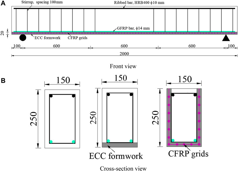
FIGURE 1. Schematic diagram of a composite beam.
The information for the tested composite beams is shown in Table 1, where the formwork type, the CFRP grid reinforcement, and the ECC strength were taken into account as variables for investigation. In the designation of the tested beams, symbols “R”, “B”, and “U” represent the reference concrete beam, the composite beam with the bottom ECC formwork, and the composite beams with the U-shaped ECC formwork, respectively. In addition, “C” in the label indicates that CFRP grid reinforcements were applied, while “−30” and “−50” are labeled to distinguish the two ECC strength grades used in the specimens.
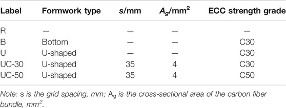
TABLE 1. Test matrix of the composite beams.
Specimen Preparation
The preparation process of the composite beams included the preparation of the ECC formwork and the casting of inner concrete. The U-shaped ECC formwork was first cast in an aluminum mold with inner dimensions of 150 mm × 250 mm × 2000 mm (see Figure 2A). A 10 mm thick ECC layer was first poured in the bottom of the aluminum mold, and then a layer of CFRP grids was put on the ECC after casting and subsequently covered with another layer of 10 mm thick ECC mixture. A similar process was adopted in the preparation of the bottom ECC formwork. After casting the bottom of the U-shaped ECC formwork, a stuffing mold was placed inside the aluminum mold reserving two 20 mm gaps on both sides between the inner and exterior molds. Two CFRP grids were fixed in the middle of the gaps before pouring the rest of the ECC mixture for the formwork sides (see Figure 2B). The cased ECC formwork was cured at room temperature for 7 days.
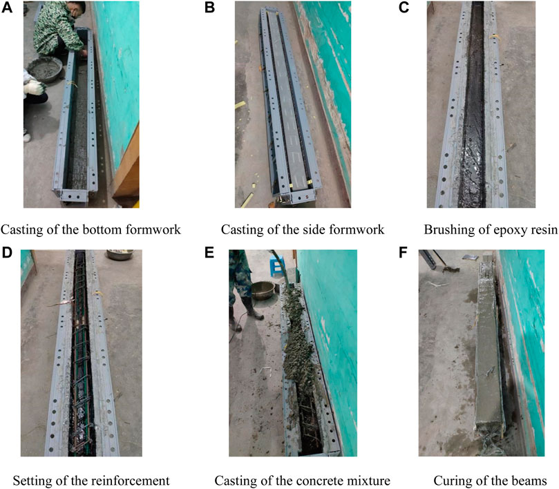
FIGURE 2. Preparation of the composite beam specimens.
After demolding the cured ECC formwork, a layer of 2 mm thick epoxy resin was brushed on the inner surfaces of the formwork (see Figure 2C), and the prepared reinforcement framework, including GFRP bars, steel bars and stirrups, was then placed into the permanent ECC formwork (see Figure 2D). Finally, the inner concrete mixture was poured and vibrated layer by layer, and the cast specimens were cured for 28 days (see Figures 2E,F).
Test Setup and Loading Pattern
As shown in Figure 3A, the composite beam was tested by a 100 kN hydraulic actuator with a four-point loading scheme. Per Chinese standard GB/T 50,152–2012 (China’ National Standard, 2012), the preloading force that was determined to be 60% of the estimated cracking load was applied to check the workability of measurement devices and eliminate gaps between the beam and supports. Formal loading was adopted as a multistage loading protocol. The load level was chosen as 5 kN before the cracking load and then changed to 10 kN until the test ended. At each load level, the applied load was sustained for approximately 5 min to measure and record any possible cracks and failure.

FIGURE 3. Test setup and measurement layout for the composite beam.
The measurement layout for the composite beams is shown in Figure 3B. The load applied by the hydraulic actuator was monitored by a load cell with a maximum capacity of 1,000 kN. The deflections at the loading points and supports were recorded by YWC-100-type displacement transducers with a displacement capacity of 100 mm and YWC-10-type displacement transducers with a displacement capacity of 10 mm, respectively. Strains across the mid-span were measured by 250 mm long handheld strain gauges at a spacing of 50 mm. In addition, BX120-5AA-type strain gauges were attached to GFRP bars and CFRP grids at the mid-span. Cracks were measured by a ZBL-F120-type crack width measuring device with a measurement range of 2 mm and a sensitivity coefficient of 0.02 mm. Once the crack widths exceeded 2 mm, they were recorded with a regular ruler by the naked eye. All load, displacement, and strain data were collected by a DH3816N static strain testing system at a frequency of 1 Hz.
Materials
The C30 concrete was composed of ordinary Portland cement labeled P. O 42.5, gravel with a particle size of 5–20 mm, river sand, and water. The mix proportion of the C30 concrete was cement: water: sand: gravel = 1:0.65:2.08:3.70. Per Chinese standard GB/T 50,081–2019 (China’ National Standard, 2019), the concrete cubes were loaded on 3,000 kN hydraulic universal testing machine, and the loading rated is 0.8 MPa/s. Per Chinese standard GB 50010–2010 (China’ National Standard, 2010), the 28-days compressive strength of the concrete was measured to be 34.2 MPa on average for 150 mm × 150 mm × 150 mm cubes under standard curing conditions (temperature 20 ± 2 °C and relative humidity RH ≥ 95%). Two strength grades of ECC were prepared in this test, which consisted of P.O.42.5 cement, class I fly ash, amorphous ultrafine silica fume, quartz sand, PVA fiber, water, water reducer and additives. The mix proportions of the ECC are listed in Table 2. The water reducer was a polycarboxylate superplasticizer with a water reduction rate of 18–25%. The RECS15-type PVA fibers (dry bundled) were provided by Kuraray Co., Ltd, and the main material parameters are shown in Table 3. Per Chinese standard JGJ 70–2009 (China’ National Standard, 2009), the material properties of the two ECCs with different strengths were tested, and the results are shown in Table 4.
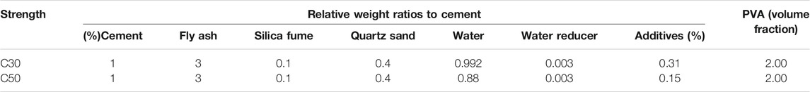
TABLE 2. ECC mix proportion.

TABLE 3. Material parameters of PVA fibers.
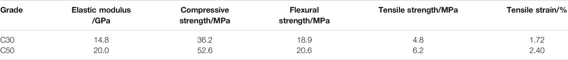
TABLE 4. Material parameters of ECCs.
The GFRP bars were composed of glass fibers and epoxy resin that were obtained by the pultrusion process and manufactured by Nanjing Fenghui Composite Material Co., Ltd. The ultimate tensile strength and elastic modulus were measured to be 712.3 MPa and 59.3 GPa, respectively. HRB400 ribbed steel bars with diameters of 6 and 10 mm were used as the stirrups and top longitudinal reinforcement, respectively. For the 6 mm diameter steel bars, the yield strength, ultimate tensile strength, elastic modulus and ultimate elongation were 425 MPa, 610 MPa, 187 GPa and 29%, respectively. For the 10 mm diameter steel bars, the yield strength, ultimate tensile strength, elastic modulus and ultimate elongation were 435 MPa, 705 MPa, 205 GPa and 22%, respectively. CFRP grids were made of continuous carbon fibers impregnated with epoxy resin, provided by Carbon Composites (Beijing) Co., Ltd. The material properties of the CFRP grids with a 4-mm2 cross-section were measured per ASTM-D882-2009 (Institute, 2009). The tensile strength and elastic modulus were 2,529 MPa and 190.2 GPa, respectively.
Test Results and Analysis
Crack Patterns and Failure Modes
Figure 4 shows the failure modes of all the tested beams. In the reference concrete beam R, the first crack was detected at a load of 14.4 kN, and its width was 0.107 mm. Typical V-shaped cracks could be observed on the beam sides, while both the crack number and width increased as the load increased. The concrete was crushed in the compression zone at an ultimate load of 140 kN (see Figure 4A), which indicated that the failure of the testing beam.
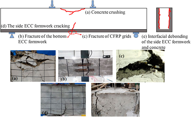
FIGURE 4. Typical failure modes of the tested beams.
In beam B with bottom ECC formwork, the first crack with a width of 0.063 mm was observed on the bottom ECC at a load of 19.7 kN (0.13 Mu). Dense and fine cracks were observed on the ECC formwork, thereby indicating the excellent crack resistance ability of the ECC, as shown in Figure 5B, which was different from the reference concrete beam R (see Figure 5A). The cracks extending from the bottom occurred first in the middle of the side concrete at a load of 30.0 kN and then extended in all areas along the beam length. At a load of 152.0 kN, the concrete was crushed in the compression zone, whereas no interfacial debonding between the ECC formwork and the concrete was observed.
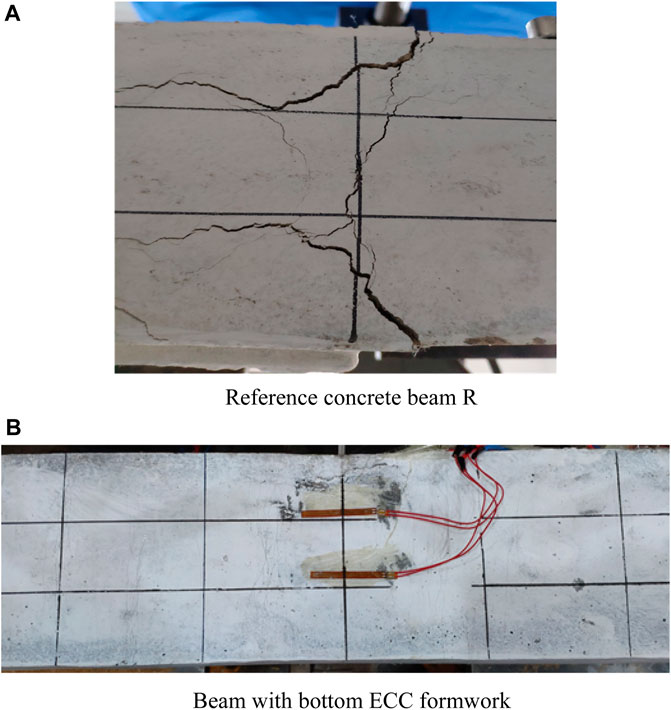
FIGURE 5. Comparison of the crack distribution in the bottom of the beam.
Beam U with U-shaped ECC formwork first cracked (0.027 mm wide) at a load of 25.0 kN (0.19 Mu) (see Figure 5B). At the load of 79.0 kN (0.62 Mu), the ECC formwork fully fractured at both sides and the bottom, and interfacial debonding with a width of 3 mm occurred between the side ECC formwork and the core concrete, as seen in Figure 4E. At this time, the bearing capacity of beam U increased slowly, whereas the deflection increased rapidly. With increasing loading, the concrete in the compression zone inside the ECC formwork was crushed at a load of 128.7 kN.
The first crack with a width of 0.063 mm was observed in beam UC-30 with U-shaped CFRP grid-reinforced ECC formwork at a load of 25.0 kN (0.17 Mu). When beam UC-30 was loaded to 147.4 KN, the ECC formwork fractured at both sides and the bottom, as seen in Figure 4D, and then the load dropped suddenly to 135 kN. The test beam then entered the horizontal stage, i.e., the deflection increased continuously while the load remained basically unchanged. The crack width of the test beam was relatively uniform during loading. The concrete in the compression zone was crushed, and the CFRP grids were fractured (as seen in Figure 4C) until a load of 146.0 kN was reached, thereby demonstrating the failure of the beam. In beam UC-50 with the C50 ECC formwork, a crack with a width of 0.027 mm emerged at 26.0 kN (0.16 Mu). At a load of 147.0 kN (0.91 Mu), the bottom of the ECC formwork fractured. The CFRP grids at the bottom fractured at a load of 153.0 kN (0.95 Mu), and the CFRP grids at both sides also fractured with continued loading. The load fluctuated between 153.0 and 156.0 kN, while the deflection increased and the concrete in the compression zone started to crush. At the ultimate load (161.9 kN), all the CFRP grids fractured, and the concrete crushed, thereby demonstrating the failure of the beam. In conclusion, the failure types of the composite beams can be summarized as: 1) concrete crushing; 2) fracture of the bottom ECC formwork; 3) fracture of CFRP grids; 4) fracture of the side ECC formwork; and 5) interfacial debonding of the side of the ECC formwork and core concrete.
Load-Deflection Behavior of Composite Beams
The test results of all beams are summarized in Table 5, while the load versus mid-span deflection curves of all the tested beams are shown in Figure 6. Compared with that of beam R, the cracking strengths corresponding to the first crack observed for beams U, UC-30 and UC-50 with U-shaped ECC formwork increased within a range of 73.6 and 80.6%, whereas the cracking load observed in beam B with bottom ECC formwork only increased by approximately 36.8%. This phenomenon demonstrated that the application of the U-shaped ECC formwork greatly improved the cracking resistance of the composite beams, and their efficiency of improvement was better than that of the bottom ECC formwork. For the ultimate load, an increase between 5.3 and 15.7% could be achieved in beams UC-30 and UC-50 when compared with the reference concrete beam. In beam B and beam U, the ultimate load of the former was improved by 8.6%, whereas that of the latter adversely decreased by 8.1%. The severe interfacial debonding between the U-shaped ECC formwork and the core concrete accounted for the above phenomenon. When the U-shaped ECC formwork was applied, the stiffness difference between the ECC and concrete resulted in interfacial debonding; accordingly, the ultimate load of composite beam U decreased.
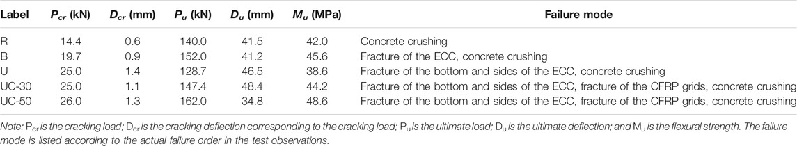
TABLE 5. Test results of all the tested beams.
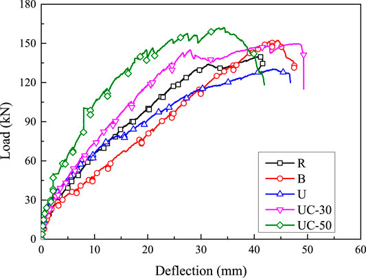
FIGURE 6. Load versus mid-span deflection curves of all the tested beams.
Strain Response
Figure 7 shows the load versus strain curves of the GFRP bars and CFRP grids at the mid-span location, which are chosen from beam UC as an example. The load-strain behavior of both the GFRP bars and CFRP grids could be divided in two stages, i.e., 1) before cracking and 2) after cracking. Before cracking, the strains of the GFRP bars and CFRP grids linearly increased with the load, and the strain development rates of the two materials were similar because the distances between the GFRP bars and CFRP grids were close. After cracking, the strain development rates of the GFRP bar and CFRP grids significantly increased, and the strain development was still approximately linear with increasing load because the two materials were both linear-elastic. Figure 8 shows the load versus the GFRP bars in beam U with pure ECC formwork and UC-30 with CFRP grid-reinforced ECC formwork. The strain of the GFRP bars in beam U was smaller than that of beam UC-30 under the same level of loading, which indicated that the embedded CFRP grids effectively carried part of the tension force from the GFRP bars. It is obvious that the CFRP grids and GFRP bars contributed to the composite beam.
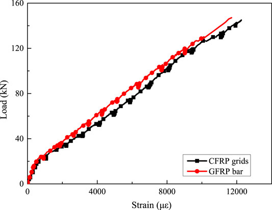
FIGURE 7. Load versus strain curves of GFRP bars and CFRP grids (taken from beam UC-30).
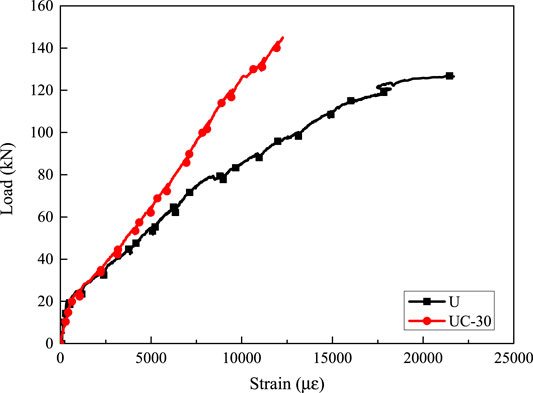
FIGURE 8. Load versus strain curves of the GFRP bars.
Moment-Curvature Response in the Pure Bending Section
Figure 9 shows the moment-curvature response in the pure bending section that is obtained from three typical beams. The slopes of the moment-curvature curves of beam B and beam UC-30 are almost the same, and both are larger than that of beam R. This indicates that the use of the ECC formwork can improve the sectional stiffness of the normal FRP reinforced concrete beam, whether the precracking stiffness or postcracking stiffness is considered. It is also evident that the ultimate moments of beam B and UC-30 are larger than that of beam R, thereby indicating that beams with ECC bottom or U-shaped ECC formwork can improve the bearing capacity. The type of ECC formwork has little effect on the bearing capacity of the composite beams. The ultimate curvatures, defined as the curvatures corresponding to the peak moments, of beam B and UC-30 are 68.73 km−1 and 68.29 km−1, respectively, whereas the ultimate deflection of beam B is smaller than that of beam UC-30, with a reduction of 14.88%. The above phenomenon can be explained as follows. The employment of CFRP grid-reinforced U-shaped ECC formwork may increase the shear stiffness of composite beams in the shear-span zone and consequently reduce the mid-span deflection. A similar conclusion was obtained by Dong (Dong et al., 2019).
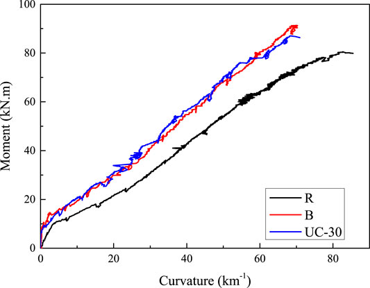
FIGURE 9. Moment-curvature responses of composite beams.
Discussion
The effects of the application of the U-shaped ECC formwork, the formwork types, the application of CFRP grids, and the strength of the ECC were compared to study the cracking performance and mechanical behavior of the tested beams. The detailed analysis is provided below.
Effect of the U-Shaped ECC Formwork
Figure 10 shows the effect of the U-shaped ECC formwork on the load-deflection relationship and load-crack width behavior by comparing reference beam R to beam U with U-shaped ECC formwork. As shown in Figure 10A, the precracking and postcracking stiffnesses of beam R were 23.45 kN/mm and 4.87 kN/mm, respectively. The precracking stiffness of beam U was 7.3% larger than that of beam R, which indicated that the use of U-shaped ECC formwork could increase the precracking stiffness of the beam. Due to the interfacial debonding in beam U, the U-shaped ECC formwork and core concrete did not work together, and thereafter, the cross-sectional stiffness was significantly reduced to 2.25 kN/mm. Compared with the case of beam R, the cracking load in beam U increased by 73.6% (Table 5), which indicates that the use of U-shaped ECC formwork can significantly improve the cracking strength. The ultimate load of beam U (128.7 kN) decreased compared to that of reference beam R (140.0 kN), with a reduction of 8.1%, which was mainly due to the interfacial debonding between the concrete and U-shaped ECC formwork. In this case, the following conclusion can be drawn: U-shaped ECC formwork had a positive effect on crack resistance due to the multicracking characteristic of ECCs, whereas a good interfacial bonding mechanism should be guaranteed. In addition, at the ultimate load, the mid-span deflection of beam U (46.5 mm) was larger than that of beam R (41.5 mm), which improved the ductility of the composite beam because of the application of the U-shaped ECC formwork.
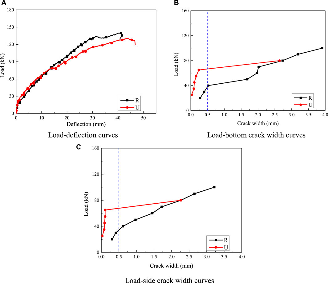
FIGURE 10. Effect of the existence of U-shaped ECC formwork.
The largest crack widths at the bottom and side of the ECC formwork were taken as the crack widths shown in Figures 10B,C, and crack widths larger than 4.0 mm were not recorded in the present study. Both the bottom and side crack widths measured in beam U were much smaller than those in beam R under the same load before interfacial debonding between the ECC formwork and core concrete occurred (at a load of 79.0 kN); see Figures 10B,C. However, after interfacial debonding, the bottom and side crack widths in beam U developed extremely fast and exceeded 2.0 mm at the next data recording process. At the bottom crack width limit of 0.5 mm specified in the Chinese standard GB50608-2010 for the serviceability limit state (SLS) (China’ National Standard, 2010), the loads obtained from beams R and U were 40.0 and 66.0 kN, corresponding to 0.29 Mu and 0.51 Mu, respectively. In beam R, only 29% of the ultimate load could be utilized at the SLS. However, in the case of U-shaped ECC formwork, the load bearing capacity corresponding to the SLS significantly improved to approximately half of the ultimate bearing capacity.
Effect of the Formwork Type
Figure 11 shows the effect of the formwork type on the load-deflection relationships and load-crack width by comparing beam B with bottom ECC formwork and beam U with U-shaped ECC formwork. As shown in Figure 11A, the precracking stiffness of beam U (25.15 kN/mm) was 22.7% larger than that of beam B (21.89 kN/mm). Similarly, the postcracking stiffness of beam U (3.45 kN/mm) was smaller than that of beam B (4.45 kN/mm) before interfacial debonding was observed in beam U (79.0 kN). The above phenomenon demonstrated that the U-shaped ECC formwork improved the cross-sectional stiffness, as the elastic modulus of the ECC was larger than that of the concrete. After interfacial debonding, the cross-sectional stiffness measured from beam U decreased compared to that of beam B, and the postdebonding stiffness of beam U was only 2.25 kN/mm. The cracking load increased by 26.9% as the ECC formwork changed from the bottom type to the U-shaped type (see Table 5). The ultimate load of beam U was weakened due to interfacial debonding and even decreased compared to that of beam B. The ultimate deflection of beam U was 12.9% larger than that of beam B. This result indicated that the beam with the U-shaped ECC formwork exhibited better ductility than the beam with the bottom ECC formwork.
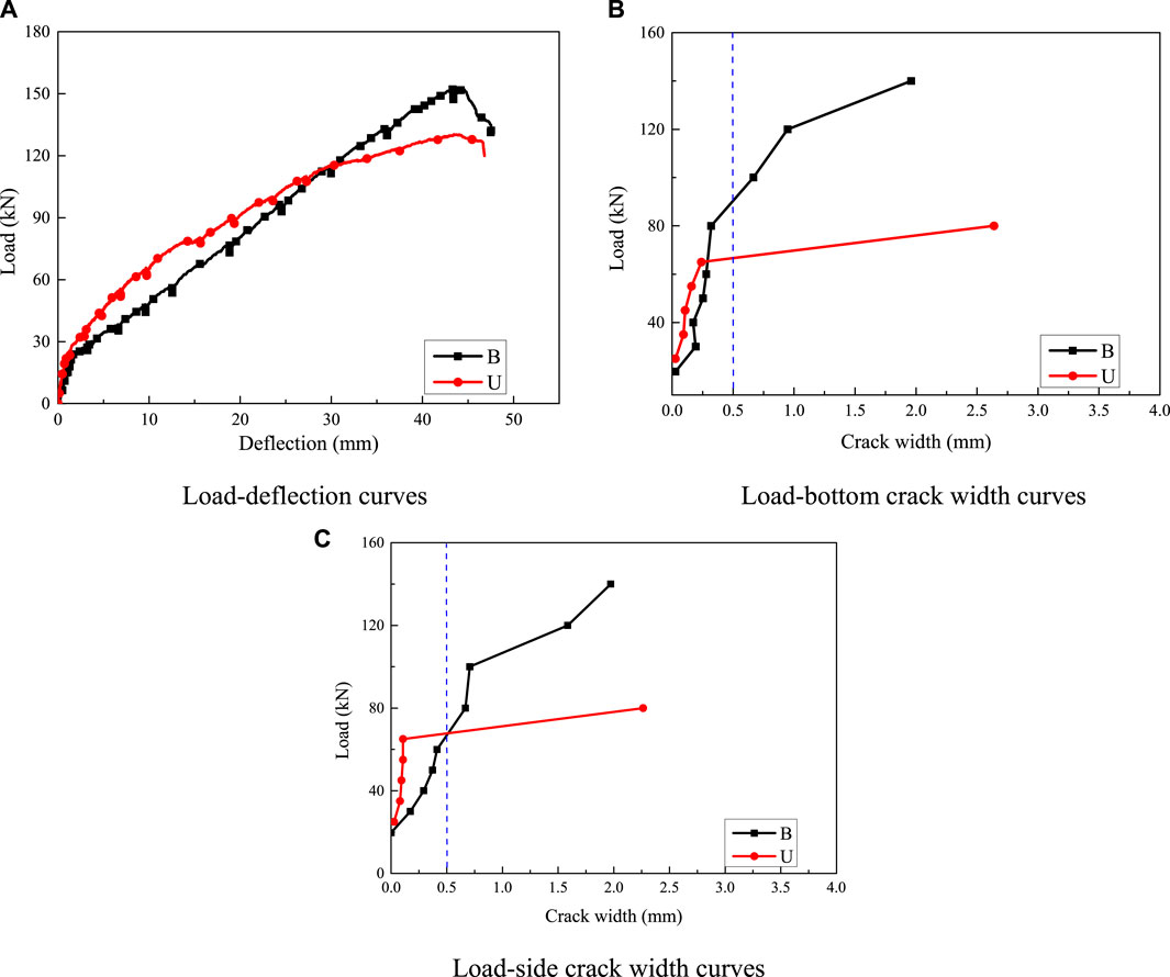
FIGURE 11. Effect of the formwork type.
The largest crack widths at the bottom and side of the ECC formwork were taken as the crack widths shown in Figures 11B,C. The development of the crack width was smaller in beam U than in beam B before interfacial debonding occurred at a load of 79.0 kN in beam U. Thus, a reasonable assumption can be drawn that the crack control ability was better in the composite beam with U-shaped ECC formwork. For beam B, the crack width developed relatively slowly before the load of approximately 80.0 kN was reached, and after that, the crack width grew fast. At the bottom crack width limit of 0.5 mm for the SLS, the loads of beams B and U were 65.6 and 66.0 kN, corresponding to 0.43 Mu and 0.51 Mu, respectively. By changing the bottom ECC formwork to U-shaped ECC formwork, the bearing capacity corresponding to the SLS in beam U was improved by 18.6% compared with the case of beam B. For the side crack width in Figure 11C, the width of beam U was smaller than that of beam B due to the existence of the side ECC formwork with a good effect on crack control.
Effect of the CFRP Grids
Figure 12 shows the effect of the CFRP grids on the load-deflection relationships and load-crack width by comparing beam U using the U-shaped ECC formwork and beam UC-30 using the U-shaped CFRP grid-reinforced ECC formwork. As shown in Figure 12A, the precracking stiffness and postcracking stiffness of beam UC-30 were 26.6 kN/mm and 5.33 kN/mm, respectively, which were both larger than those of beam U due to the existence of CFRP grids. This result indicated that using CFRP grids to strengthen the U-shaped ECC formwork had a good effect on improving the stiffness of the composite beam. The employment of CFRP grids had little effect on constraining the cracking development of the composite beam during loading. The cracking loads of beams U and UC-30 were both 25 kN. The ultimate loads of beams U and UC-30 were 128.7 and 147.4 kN, respectively. An increase of 14.5% in the bearing capacity was observed in beam UC-30. This shows the enhancement effect of the U-shaped CFRP grid-reinforced ECC formwork on the beam. In addition, the ultimate deflection of beam U (46.5 mm) was smaller than that of beam UC-30 (48.4 mm).
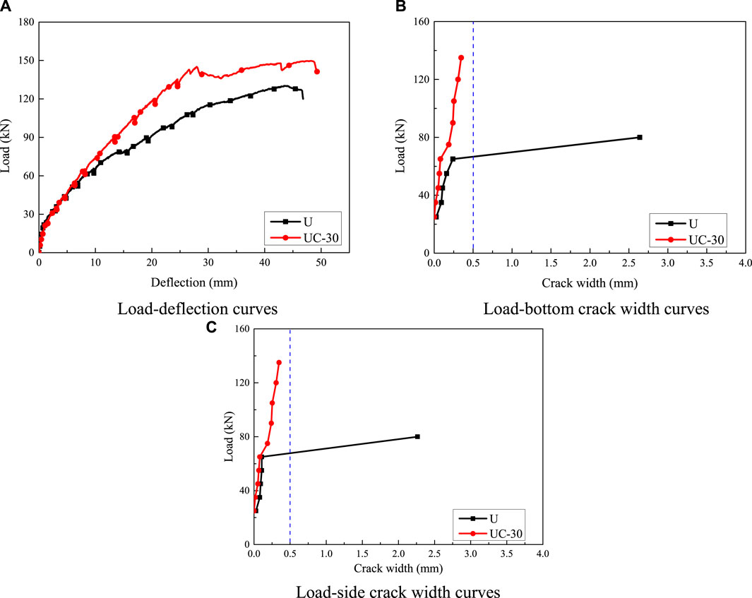
FIGURE 12. Effect of the CFRP grids.
The largest crack widths at the bottom and side of the ECC formwork were taken as the crack widths shown in Figures 12B,C, and crack widths larger than 4.0 mm were not recorded in the present study. It is obvious that the crack width in beam UC-30 was smaller than that in beam U under the same load during the entire loading history. At the bottom crack width limit of 0.5 mm for the SLS, the load of beam U was 66 kN, corresponding to 0.51 Mu, where the maximum bottom crack width in beam UC-30 was smaller than 0.5 mm during the entire loading process. In the case of using the CFRP grid-reinforced ECC formwork, the bearing capacity corresponding to the SLS improved significantly.
Effect of the ECC Strength
Figure 13 shows the effect of the concrete strength on the load-deflection relationships and load-crack width by comparing beam UC-30 with C30 ECC and beam UC-50 with C50 ECC. As shown in Figure 13A, the precracking stiffness of beam UC-50 (29.97 kN/mm) was 12.7% larger than that of beam UC-30 (26.6 kN/mm), and the postcracking stiffness of beam UC-50 (7.27 kN/mm) was also larger than that of beam UC-30 (5.33 kN/mm), as the elastic modulus of C50 concrete was larger than that of C30 concrete. The mid-span deflection of beam UC-50 decreased by 28.0% compared with that of beam UC-30 at the ultimate load. The cracking loads of beams UC-30 and UC-50 were similar, and the difference was less than 4%. Regarding the ultimate load, an increment of 9.9% was obtained in beam UC-50 using higher ECC strength compared with beam UC-30. The higher ECC strength could sustain more load in the composite beam.
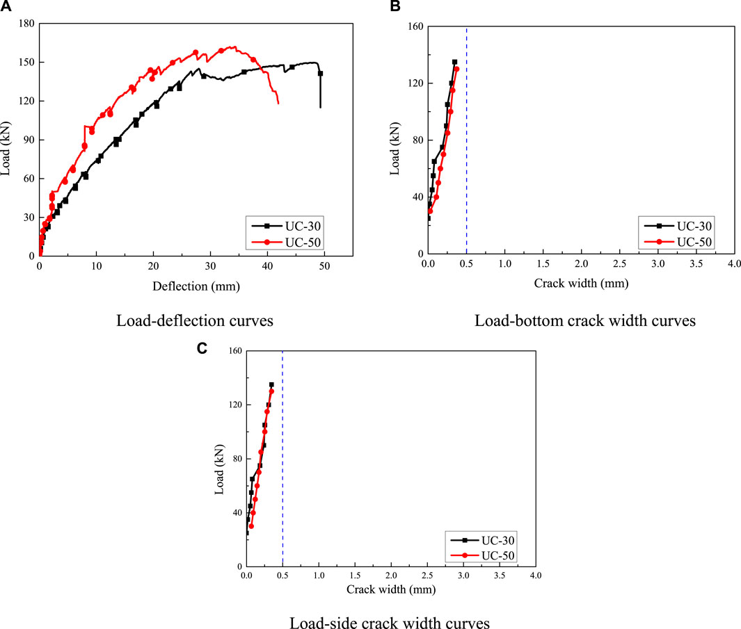
FIGURE 13. Effect of the ECC strength.
The largest crack widths at the bottom and side of the ECC formwork were taken as the crack widths shown in Figures 13B,C. The crack widths developed at a similar rate in beams UC-30 and UC-50 during the entire loading history, where a relatively smaller crack width under the same load level was observed in beam UC-30, thereby indicating that the increased ECC strength showed a negative effect on the crack control ability. Both beams UC-30 and UC-50 satisfied the bottom crack width limit of 0.5 mm for the SLS during the entire loading history.
Conclusion
In this paper, the flexural performance of GFRP-reinforced composite beams with U-shaped CFRP grid-reinforced ECC stay-in-place formwork was studied through bending experiments. The application of U-shaped ECC formwork, different formwork types, the CFRP grids, and various ECC strengths served as the test variables. The failure modes, load-deflection and stain response were analyzed. Based on the experiments, the following results can be drawn:
(1) ECCs could be an ideal strengthening material to improve the flexural performance of concrete beams. The cracking load and ultimate load of beam B with bottom ECC formwork were 36.81 and 8.57% larger than those of reference beam R. Moreover, the interfacial bond between the ECC and normal concrete performs well during loading.
(2) The same failure modes were observed in GFRP-reinforced composite beams strengthened with ECC formwork and CFRP grid-reinforced ECC formwork at the ultimate load, where the concrete was crushed and GFRP bars were not fractured. Both the ECC formwork and CFRP grids at the bottom and sides were fractured in all the beams during the loading process.
(3) The CFRP grids used could improve the cracking capacity and bearing capacity of composite structures. In terms of the composite beam with CFRP grid-reinforced U-shaped ECC formwork, the cracking load and bearing capacity were 78.57–85.71% and 5.29–15.71% larger than those of beam R. Moreover, the employment of CFRP grid-reinforced U-shaped ECC formwork can improve the shear stiffness.
(4) The U-shaped ECC formwork exhibited better ductility and crack control effect than the beam with the bottom ECC formwork. In terms of different strength of U-shaped ECC formwork the increase in ECC strength from C30 to C50 was not obvious with the increase in the cracking load, and a higher ECC strength could increase the ultimate load of composite beams by 9.9%.
(5) The employment of U-shaped ECC formwork had a positive effect on the crack resistance at the serviceability limit, which will be of great benefit to structural durability. The composite beams showed better performance of cracking load, stiffness and bearing capacity than those of reference beam corresponding to the SLS.
Data Availability Statement
The original contributions presented in the study are included in the article/Supplementary Material, further inquiries can be directed to the corresponding author.
Author Contributions
CW Conceptualization, Methodology, Writing- Original draft preparation. YS Investigation, Software, Visualization, Writing- Original draft preparation. PZ Conceptualization, Data curation, Writing- Reviewing and Editing. HZ Validation, Writing- Reviewing and Editing. DG Validation, Writing- Reviewing and Editing SS Supervision.
Funding
This study was funded by financial support from the National Natural Science Foundation of China (U1904177, 51508519, 52108119), the Natural Science Foundation of Jiangsu Province (Grant Nos. BK20200376), and the Fundamental Research Funds for the Central Universities (Grant Nos. 2242021R10081).
Conflict of Interest
The authors declare that the research was conducted in the absence of any commercial or financial relationships that could be construed as a potential conflict of interest.
Publisher’s Note
All claims expressed in this article are solely those of the authors and do not necessarily represent those of their affiliated organizations, or those of the publisher, the editors, and the reviewers. Any product that may be evaluated in this article, or claim that may be made by its manufacturer, is not guaranteed or endorsed by the publisher.
References
Akiyama, M., Frangopol, D. M., and Suzuki, M. (2012). Integration of the Effects of Airborne Chlorides into Reliability-Based Durability Design of Reinforced concrete Structures in a marine Environment. Struct. Infrastructure Eng. 8, 125–134. doi:10.1080/15732470903363313
Al-Salloum, Y. A., El-Gamal, S., Almusallam, T. H., Alsayed, S. H., and Aqel, M. (2013). Effect of Harsh Environmental Conditions on the Tensile Properties of GFRP Bars. Composites B: Eng. 45 (1), 835–844. doi:10.1016/j.compositesb.2012.05.004
Al-Saoudi, A., Kalfat, R., Al-Mahaidi, R., Cervenka, J., and Pryl, D. (2021). Numerical and Experimental Investigation into the Fatigue Life of FRP Bonded to concrete and Anchored with Bidirectional Fabric Patches. Eng. Structures 239, 112335. doi:10.1016/j.engstruct.2021.112335
Altalmas, A., El Refai, A., and Abed, F. (2015). Bond Degradation of basalt Fiber-Reinforced Polymer (BFRP) Bars Exposed to Accelerated Aging Conditions. Construction Building Mater. 81, 162–171. doi:10.1016/j.conbuildmat.2015.02.036
Balendran, R. V., Rana, T. M., Maqsood, T., and Tang, W. C. (2002). Application of FRP Bars as Reinforcement in Civil Engineering Structures. Struct. Surv. 20, 62–72. doi:10.1108/02630800210433837
Barris, C., Torres, L., Vilanova, I., Miàs, C., and Llorens, M. (2017). Experimental Study on Crack Width and Crack Spacing for Glass-FRP Reinforced concrete Beams. Eng. Structures 131, 231–242. doi:10.1016/j.engstruct.2016.11.007
Cai, J., Pan, J., and Zhou, X. (2017). Flexural Behavior of basalt FRP Reinforced ECC and concrete Beams. Construction Building Mater. 142, 423–430. doi:10.1016/j.conbuildmat.2017.03.087
China’ National Standard (2012). GB/T 50152-2012 Standard for Test Method of concrete Structures. China.
China’ National Standard (2010a). GB50608-2010 Technical Code for Infrastructure Application of FRP Composites. China.
China’ National Standard (2009). JGJ/T70-2009 Standard for Test Method of Performance on Building Mortar. China.
Dong, H.-L., Zhou, W., and Wang, Z. (2019). Flexural Performance of concrete Beams Reinforced with FRP Bars Grouted in Corrugated Sleeves. Compos. Structures 215, 49–59. doi:10.1016/j.compstruct.2019.02.052
Dong, Z., Wu, G., Zhao, X.-L., Zhu, H., and Shao, X. (2019). Behaviors of Hybrid Beams Composed of Seawater Sea-Sand concrete (SWSSC) and a Prefabricated UHPC Shell Reinforced with FRP Bars. Construction Building Mater. 213, 32–42. doi:10.1016/j.conbuildmat.2019.04.059
Gar, S. P., Mande, J. B., and Hurlebaus, S. (2018). Deflection of FRP Prestressed Concrete Beams. J. Compos. Constr. 22 (2), 1–11. doi:10.1061/(asce)cc.1943-5614.0000832
Ge, W., Ashour, A. F., Cao, D., Lu, W., Gao, P., Yu, J., et al. (2019). Experimental Study on Flexural Behavior of ECC-concrete Composite Beams Reinforced with FRP Bars. Compos. Structures 208, 454–465. doi:10.1016/j.compstruct.2018.10.026
Ge, W., Wang, Y., Ashour, A., Lu, W., and Cao, D. (2020). Flexural Performance of concrete Beams Reinforced with Steel-FRP Composite Bars. Archiv.Civ.Mech.Eng 20 (2), 1–17. doi:10.1007/s43452-020-00058-6
Huang, B.-T., Weng, K.-F., Zhu, J.-X., Xiang, Y., Dai, J.-G., and Li, V. C. (2021). Engineered/strain-hardening Cementitious Composites (ECC/SHCC) with an Ultra-high Compressive Strength over 210 MPa. Composites Commun. 26, 100775. doi:10.1016/j.coco.2021.100775
Huang, B.-T., Wu, J.-Q., Yu, J., Dai, J.-G., Leung, C. K. Y., and Li, V. C. (2021). Seawater Sea-Sand Engineered/strain-Hardening Cementitious Composites (ECC/SHCC): Assessment and Modeling of Crack Characteristics. Cement Concrete Res. 140, 106292. doi:10.1016/j.cemconres.2020.106292
Institute (2009). ASTM D882-2009 Standard Test Method for Tensile Properties of Thin Plastic Sheeting. United States.
Issa, M. S., and Ismail, E.-S. (2020). Long-term Deflections of FRP Reinforced concrete Beams. HBRC J. 16 (1), 269–282. doi:10.1080/16874048.2020.1812897
Kazemi, M., Li, J., Lahouti Harehdasht, S., Yousefieh, N., Jahandari, S., and Saberian, M. (2020). Non-linear Behaviour of concrete Beams Reinforced with GFRP and CFRP Bars Grouted in Sleeves. Structures 23, 87–102. doi:10.1016/j.istruc.2019.10.013
Kim, Y. J. (2019). State of the Practice of FRP Composites in Highway Bridges. Eng. Structures 179, 1–8. doi:10.1016/j.engstruct.2018.10.067
Li, V. C., and Leung, C. K. Y. Steady‐State and Multiple Cracking of Short Random Fiber Composites. J. Eng. Mech. 118 (11), 2246–2264. doi:10.1061/(asce)0733-9399(1992)118:11(2246)
Li, V. C., and Wang, S.and View Correspondence (2002). Flexural Behaviors of Glass Fiber-Reinforced Polymer (GFRP) Reinforced Engineered Cementitious Composite Beams. Mj 99 (1), 11–21. doi:10.14359/11311
Li, V. C., Wu, C., Wang, S., Ogawa, A., and Saito, T. (2002). Interface Tailoring for Strain-Hardening Polyvinyl Alcohol-Engineered Cementitious Composite (PVA-ECC). Mj 99 (5), 463–472. doi:10.14359/12325
Liu, H., Zhang, Q., Gu, C., Su, H., and Li, V. (2017). Influence of Microcrack Self-Healing Behavior on the Permeability of Engineered Cementitious Composites. Cement and Concrete Composites 82, 14–22. doi:10.1016/j.cemconcomp.2017.04.004
Liu, J., Jiang, Z., Zhao, Y., Zhou, H., Wang, X., Zhou, H., et al. (2020). Chloride Distribution and Steel Corrosion in a Concrete Bridge after Long-Term Exposure to Natural Marine Environment. Materials 13 (17), 3900. doi:10.3390/ma13173900
Liu, Y., Tafsirojjaman, T., Dogar, A. U. R., and Hückler, A. (2021). Bond Behaviour Improvement between Infra-lightweight and High Strength Concretes Using FRP Grid Reinforcements and Development of Bond Strength Prediction Models. Construction Building Mater. 270, 121426. doi:10.1016/j.conbuildmat.2020.121426
Merwe, F. v. d., and Hofmann, P. (2020). Guidance on the Design and Use of Fibre-Reinforced Polymer (FRP) Soil Nails and Ground Anchors - Geotechnical Engineering. Civil Eng. 2020 (3), 56–63.
Qiao, Z., Pan, Z., Leung, C. K. Y., and Meng, S. (2017). Experimental Study and Analysis of Flexural Behavior of ECC/RC Composite Beams. J. Southeast University(Natural Sci. Edition) 47 (4), 724–731.
Qin, F., Zhang, Z., Yin, Z., Di, J., Xu, L., and Xu, X. (2020). Use of High Strength, High Ductility Engineered Cementitious Composites (ECC) to Enhance the Flexural Performance of Reinforced concrete Beams. J. Building Eng. 32, 101746. doi:10.1016/j.jobe.2020.101746
Siwowski, T., Kulpa, M., Rajchel, M., and Poneta, P. (2018). Design, Manufacturing and Structural Testing of All-Composite FRP Bridge Girder. Compos. Structures 206, 814–827. doi:10.1016/j.compstruct.2018.08.048
Wang, Z., Zhao, X.-L., Xian, G., Wu, G., Singh Raman, R. K., and Al-Saadi, S. (2017). Durability Study on Interlaminar Shear Behaviour of basalt-, Glass- and Carbon-Fibre Reinforced Polymer (B/G/CFRP) Bars in Seawater Sea Sand concrete Environment. Construction Building Mater. 156, 985–1004. doi:10.1016/j.conbuildmat.2017.09.045
Wang, Z., Zhao, X.-L., Xian, G., Wu, G., Singh Raman, R. K., Al-Saadi, S., et al. (2017). Long-term Durability of basalt- and Glass-Fibre Reinforced Polymer (BFRP/GFRP) Bars in Seawater and Sea Sand concrete Environment. Construction Building Mater. 139, 467–489. doi:10.1016/j.conbuildmat.2017.02.038
Xu, J., and Li, Z. (2012). A Review on Ecological Engineering Based Engineering Management. Omega 40, 368–378. doi:10.1016/j.omega.2011.06.004
Yuan, F., Pan, J., and Leung, C. K. Y. (2013). Flexural Behaviors of ECC and Concrete/ECC Composite Beams Reinforced with Basalt Fiber-Reinforced Polymer. J. Compos. Constr. 17 (5), 591–602. doi:10.1061/(asce)cc.1943-5614.0000381
Zafari, B., Qureshi, J., Mottram, J. T., and Rusev, R. (2016). Static and Fatigue Performance of Resin Injected Bolts for a Slip and Fatigue Resistant Connection in FRP Bridge Engineering. Structures 7 (1), 71–84. doi:10.1016/j.istruc.2016.05.004
Zhang, P., Su, Y., Liu, Y., Gao, D., and Sheikh, S. A. (2021). Flexural Behavior of GFRP Reinforced concrete Beams with CFRP Grid-Reinforced ECC Stay-In-Place Formworks. Compos. Structures 277, 114653. doi:10.1016/j.compstruct.2021.114653
Zhang, W., François, R., Cai, Y., Charron, J.-P., and Yu, L. (2020). Influence of Artificial Cracks and Interfacial Defects on the Corrosion Behavior of Steel in concrete during Corrosion Initiation under a Chloride Environment. Construction Building Mater. 253, 119165. doi:10.1016/j.conbuildmat.2020.119165
Zhang, Z., Liu, S., Yang, F., Weng, Y., and Qian, S. (2021). Sustainable High Strength, High Ductility Engineered Cementitious Composites (ECC) with Substitution of Cement by rice Husk Ash. J. Clean. Prod. 317, 128379. doi:10.1016/j.jclepro.2021.128379
Zhang, Z., Qin, F., Ma, H., and Xu, L. (2020). Tailoring an Impact Resistant Engineered Cementitious Composite (ECC) by Incorporation of Crumb Rubber. Construction Building Mater. 262, 120116. doi:10.1016/j.conbuildmat.2020.120116
Zhang, Z., Yang, F., Liu, J.-C., and Wang, S. (2020). Eco-friendly High Strength, High Ductility Engineered Cementitious Composites (ECC) with Substitution of Fly Ash by rice Husk Ash. Cement Concrete Res. 137, 106200. doi:10.1016/j.cemconres.2020.106200
Zheng, Y., Zhang, L. F., and Xia, L. P. (2018). Investigation of the Behaviour of Flexible and Ductile ECC Link Slab Reinforced with FRP. Construction Building Mater. 166, 694–711. doi:10.1016/j.conbuildmat.2018.01.188
Keywords: fiber-reinforced polymer (FRP), engineered cementitious composites (ECC), CFRP grids, u-shaped ECC formwork, flexural performance
Citation: Wu C, Su Y, Zhang P, Zhu H, Gao D and Sheikh SA (2022) Experimental Study of GFRP Reinforced Concrete Beams With U-Shaped CFRP Grid-Reinforced ECC Stay-in-Place Formwork. Front. Mater. 9:872232. doi: 10.3389/fmats.2022.872232
Received: 09 February 2022; Accepted: 24 February 2022;
Published: 14 March 2022.
Edited by:
Zhigang Zhang, Chongqing University, ChinaReviewed by:
Ali Raza, University of Engineering and Technology Taxila, PakistanYang Zou, Chongqing Jiaotong University, China
Copyright © 2022 Wu, Su, Zhang, Zhu, Gao and Sheikh. This is an open-access article distributed under the terms of the Creative Commons Attribution License (CC BY). The use, distribution or reproduction in other forums is permitted, provided the original author(s) and the copyright owner(s) are credited and that the original publication in this journal is cited, in accordance with accepted academic practice. No use, distribution or reproduction is permitted which does not comply with these terms.
*Correspondence: Pu Zhang, emhwdUB6enUuZWR1LmNu