 Chang Wu
 Yanli Su
 Yu Sun1
94% of researchers rate our articles as excellent or good
Learn more about the work of our research integrity team to safeguard the quality of each article we publish.
Find out more
ORIGINAL RESEARCH article
Front. Mater., 14 April 2022
Sec. Structural Materials
Volume 9 - 2022 | https://doi.org/10.3389/fmats.2022.869835
This article is part of the Research TopicAdvanced Concretes and Their Structural ApplicationsView all 23 articles
The ultra-high tensile ductility of ECC provides an alternative way to enhance the ductility of structural members by using high-ductile matrix material instead of simply increasing reinforcements. However, the application of ECC members is still limited due to the relatively short research time and the lack of design specifications. Being equivalent to eccentric compressive members, a sectional analysis of RECC columns subjected to combined lateral load and axial compression are proposed in this paper. Based on the design theory of load capacity of eccentric compression columns and the unique constitutive model of ECC, the calculation equations for the sectional load capacity of RECC columns are derived. The analytical prediction of the load capacity of RECC column is evaluated in comparison with that of experiments that confirm the capacity of the proposed calculation method to capture the behavior of the RECC column accurately. The strength-interaction diagrams showing the axial force-moment (N-M) interaction curves are then constructed for analysis using the proposed calculation equations. A parametric study is also carried out by using the proposed calculation equations, demonstrating the effects of ultimate tensile strain of ECC, compressive and tensile strength of ECC, yield strength of steel bar, and reinforcement ratio on the N-M interaction curves of RECC columns. The investigations exhibited in this paper are expected to provide insight into the design principles of RECC columns.
Reinforced concrete (RC) columns are the lateral force resistance members in frame structures, whose seismic performance directly affects the performance of the whole structure. Modern seismic design methodology requires structural members to possess sufficient ductility and energy-absorption capacity. In some cases, RC short columns are unavoidable vertical load-bearing members in concrete structures, which are used widely in various building structures (Deng et al., 2015; Wu et al., 2017a, 2017b, 2020; Hu et al., 2021; Liu et al., 2021). However, RC short columns have poor deformation capacity and high stiffness, which are at risk of catastrophic brittle failure during earthquakes due to the intrinsic drawbacks of concrete, i.e., low tensile strength, poor toughness, and brittle failure (Doǧangün, 2004; Li and Huang, 2014; Wang, 2008). To avoid the brittle failure of concrete columns from both lateral and axial loads, the present design philosophy for RC columns is to place massive reinforcements in the expected plastic hinge zone to enhance the ductility of the concrete columns. However, in this case, dense reinforcements may create difficulties during the pouring of concrete, resulting in poor quality of concrete members. In addition, the concrete covers cannot be confined by the transverse reinforcements and, thus, may spall off during an earthquake.
In the early 1990s, a new cement-based composite material reinforced with randomly distributed short fibers called engineered cementitious composite (ECC) was proposed by Li (1993). Compared with conventional concrete, ECC possesses much higher ductility in tension attributed to its multiple cracking behavior and pseudo strain-hardening characteristics under tension (Li and Leung, 1992; Li, 1993; Yang et al., 2008; Zhang et al., 2011; Li et al., 2019; Maalej et al., 1995). The ultimate tensile strain of ECC can reach more than 3%, whereas the opening of each crack is usually controlled to be less than 60 μm when applying short fibers of less than 2% by volume (Yang et al., 2008; Zhang et al., 2011; Yuan et al., 2013; Zhang et al., 2020a; Zhang Z. et al., 2021). Moreover, in recent years, ultra-high-strength ECC has been developed with a compressive strength of more than 210 MPa and an excellent tensile strain capacity of 2%–11% (Huang et al. (2021); Xu et al., 2022). Due to its ultra-high-tensile ductility, high-strength ECC/ECC is being considered for replacing conventional concrete in structures in high-intensity earthquake regions (Maruta et al., 2005; Paulay, 2005; Montesinos and Gustavo, 2005; Qudah and Mohamed, 2014; Wu et al., 2017a; Zhang et al., 2020b), which provides an alternative way to enhance the ductility of structural members by using high-ductile matrix material instead of simply increasing reinforcements (Qin et al., 2020).
Some efforts have been made to investigate the mechanical performance of reinforced ECC (RECC) columns or RC/RECC composite columns (Cai et al., 2018; Zhang Y. et al., 2021; Li L. Z. et al., 2019; Yuan et al., 2019; Li F. et al., 2019; Li et al.,2020). Previous investigations by the first author (Wu et al., 2017a) indicate that replacing concrete with ECC material can improve the shear strength and energy dissipation capacity of the short columns. Pan et al. (2020) investigated the seismic behavior of RECC/C composite columns through experimental and numerical approaches. Results show that RECC/C composite columns had better shear capacity and higher ductility as compared with the RC column. Zhang et al. (2019) investigate the performance of RECC short columns, RC columns, and H-steel reinforced ECC short columns. Results show that the RECC columns had better crack control capacity, shear strength, and energy capacity than that of RC columns. Several studies have been done for investigating the behavior of reinforced ECC columns under eccentric compression (Yuan et al., 2018; Adnan and Mashshay, 2020; Cai et al., 2020; Li et al., 2019).
However, the application of ECC members is still limited due to the relatively short research time and the lack of design specifications. Per the code of concrete structures in China (GB50010-2010) (China’s National Standard), the calculation theory of the strength of compression members has been mature. A similar method is provided in the Technical Specification for Fiber Reinforced Concrete Structures (CECS 38: 2004) for calculating the sectional load capacity of steel fiber–reinforced concrete members under eccentric compression. However, these specifications are not perfectly suitable for ECC members. Recently, studies on the calculation of flexural strength were more mature in the case of RECC beams (Cui et al., 2021; Qiao et al., 2021; Wang et al., 2021). In the case of RECC columns, Li L. Z. et al. (2019) study the behavior of reinforced, high-strength ECC columns under eccentric compression experimentally, and an analytical model is proposed for the load-bearing capacity of RECC columns under large eccentric compression. Yuan et al. (2018) tested eight steel-reinforced columns with various longitudinal reinforcement ratios and load eccentricities under eccentric compression; in addition, a theoretical model is proposed to predict the moment-curvature response of the RECC column.
In this paper, according to mechanical characteristics, the critical section of an RECC column subjected to vertical axial compression and horizontal load is equivalent to a critical section of an eccentric compressive member. Based on the design theory of the load capacity of eccentric compression columns and the unique constitutive model of ECC, the calculation equations for the sectional load capacity of RECC columns were derived. The analytical prediction of the load capacity of RECC columns was evaluated in comparison with that of experiments that confirm the capacity of the proposed calculation method to capture the behavior of RECC columns accurately. The strength interaction diagrams showing the axial force-moment (N-M) interaction curves were then constructed for analysis using the proposed calculation equations. A numerical parametric study on the flexural performance of RECC columns was also carried out by using the proposed calculation equations, which was expected to provide insight on the design principles of RECC columns.
The following assumptions are used in the analysis of load capacity of the critical cross-section of RECC columns:
1) The normal strain distribution along the cross-section of the specimen conforms to the plane cross-section assumption.
2) The tensile strength of ECC is not neglected after cracking. The ultimate tensile strain of ECC usually could reach more than 3% (Li et al., 2001; Mishra and Yu, 2019; Huang et al., 2021), which is much larger than the yield strain of the tensile steel bar (about 0.2%). Columns are less likely to be damaged due to ultimate tensile strain of ECC materials. Therefore, the contribution of ECC in the tensile zone should be considered in the entire loading history.
3) Steel bars and ECC can work together and deform coordinately. Li (Li et al., 2019) confirms through experiments that, compared with ordinary RC beams, the deformations of steel bars and ECCs are more coordinated. It is reasonable to ignore the relative slip between steel bars and ECCs in theoretical analysis.
4) The “second order effect” is ignored. Because RECC short columns with l0/h ≤ 5 are analyzed in this paper, the influence of the second order effect can be generally ignored.
5) The ideal elastoplastic model is adopted for the constitutive relation of steel bars. The constitutive relation expressions of steel bars are as follows.
where fy is the yield strength of steel bars; εsy and εsu are the yield strain and ultimate strain of steel bars, respectively; and Es is the modulus of elasticity of steel bars.
The tensile stress–strain relation of ECC can be expressed with the trilinear model and divided into three stages: linear elastic, strain hardening, and strain softening stages, as shown in Figure 1A. In this paper, the stress–strain relationship of ECC is simplified to a bilinear model, and the tensile stress is conservatively taken as the cracking strength, ft0 as shown in Figure 1B. The strain-hardening stage is assumed to be flat, ignoring the increasing of the stress for two reasons. First, the assumption could reduce a little accuracy, but the result is conservative, and the error is very small, which is acceptable from the design perspective. Second, the ideal elastoplastic model can significantly simplify the calculation and is easier to handle by engineers in the structural design. In addition, a similar simplified stress–strain relationship of ECC is also used by other researchers (Zheng et al., 2016; Ge et al., 2018; Wang et al., 2021), and they obtain reasonable results. The relationship of strain and stress of ECC can be written as Eq. 2. The simplified bilinear model used in this paper can make the calculation results conservative, which is suitable for design purposes.
where εt0 and εtu are the cracking and ultimate strain of ECC, respectively, and E is the modulus of elasticity of ECC.
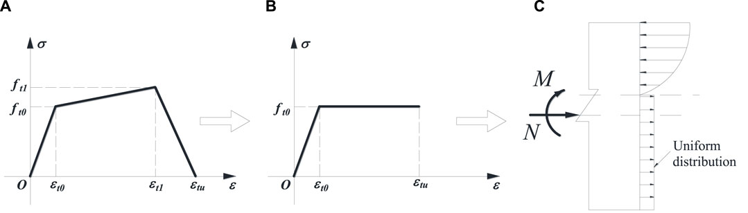
FIGURE 1. Simplification of ECC stress distribution in the tensile zone. (A) Trilinear model for the tensile stress-strain relationship of ECC. (B) Simplified bilinear model for the tensile stress-strain relationship of ECC. (C) Uniform distribution of the stress in tensile zone.
The cracking strain εt0 is basically a very small magnitude and the tensile stress distribution along the cross-section of the ECC member in the tensile zone can be further simplified to a uniform rectangular stress diagram as shown in Figure 1C.
In the calculation of the cross-sectional bearing capacity of RECC members, the compressive stress–strain relationship curve of ECC defined in reference Wu et al. (2016) is employed and further simplified as shown in Figure 2. The simplified compressive relationship of stress and strain can be expressed as
where fc and εc represent the peak stress and strain, respectively; εcu represents the ultimate compressive strain; and ζ is the parameter controlling the initial stiffness. For concrete, ζ is taken as 2 and for ECC, ζ can be approximated to 1.5.
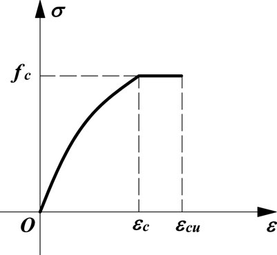
FIGURE 2. Simplification of compressive stress–strain curve of ECC.
According to different loading conditions, eccentric compression members can be divided into large and small eccentric compression. In large eccentric compression, with the increase of load, the steel bar away from the eccentric force side is first yielded, and then ECC at the edge of the compression zone near the eccentric force is crushed, resulting in the failure of the member. In small eccentric compression, most or even the whole cross-section of the member is under compression. The steel bar away from the eccentric force side does not yield, even in tension, whereas the ECC at the edge of the compression zone near the eccentric force side crushes. Because the small eccentric compressive failure is brittle, it is generally avoided in design. In GB50010-2010, the axial compression ratio is limited to prevent the occurrence of small eccentric compression failure.
For the compression-bending members, regardless of whether they are in the state of large or small eccentric compression, ECC in the compressive zone near the eccentric force side would be crushed at the ultimate load. This indicates that the column reached the ultimate bearing capacity. Therefore, it is assumed that, when the RECC member reaches the ultimate bearing capacity, the compressive strain of ECC at the edge of the compressive zone reaches its ultimate compressive strain, namely, ε = εcu.
It can be seen from the definition of large and small eccentric compression failure that the main difference between them is whether the steel bars in the tension zone away from the eccentric force are loaded to yield when the member is damaged. Therefore, the boundary between both failures can be defined as the condition when the stress of the steel bars in the tensile zone reaches their yield strength, the strain at the edge of ECC near the eccentric force reaches the ultimate compressive strain (εcu), simultaneously, as seen in Figure 3. According to the plane cross-section assumption, it can be expressed as
where εy is the yield strain of the steel bar, h0 is the effective depth of the cross-section, and xcb is the critical compressive height.
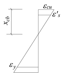
FIGURE 3. Strain distribution of the cross-section under balance failure.
The critical compressive height can be obtained by Eq. 4 as follows:
where fy is the yield stress of the steel bar and Es is the elastic modulus of the steel bar.
The large and small eccentric compression can be distinguished by the critical compressive height (xcb). When the actual compressive height (xc) is smaller than the critical compressive height (xcb), the cross-section is in the state of large eccentric compression. Conversely, when xc > xcb, the cross-section is in the state of small eccentric compression.
Figure 4 shows the strain and stress distribution of the cross-section. In the figure, As and A′s are the area of tensile and compressive steel bars, respectively; σs and σ′s are the stress of the tensile and compressive steel bars, respectively; εs and ε′s are the strain of the tensile and compressive steel bars, respectively; h is the height of the cross-section and h0 is the effective height of the cross-section; as and a′s are the distance from the center to the edge of the steel bar in the tensile and compressive zones of the cross-section, respectively; Ct and Cc are the resultant force of ECC stress in the tensile and compression zones, respectively; xc and xt are the height of the compressive and tensile zones of ECC, respectively; and yc is the distance from the stress resultant point of the compressive zone to the edge of the compressive zone.
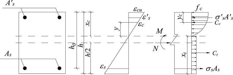
FIGURE 4. Stress and strain distribution.
For large eccentric compression members, the steel bars on one side of the tension zone far from the eccentric force reaches the yield strength (fy) in the ultimate state, and the stress of the compression steel bar near the eccentric force is related to the height of the compression zone. Therefore, in the ultimate state, the strain of the compressive steel bar can be expressed as
To ensure that the compressive steel bar reaches the yield strength in the ultimate state, the height of the compression zone should satisfy the following inequality:
According to the results of the ECC compressive test, εcu can be conservatively taken as 0.006. The yield strain of the HRB400 steel bar (εy') is taken as 0.002, and xc ≥ 1.5as′ can be obtained by inserting εy' into the right end of Eq. 7. For eccentric compression members, this condition can generally be satisfied; therefore, in this paper, the compressive steel bar near the eccentric force side yields when it reaches the ultimate state.
According to the equilibrium condition of cross-section force shown in Figure 4, the equations of axial force (N) and flexural moment (M) under large eccentric compression can be expressed as
The resultant force of ECC compression zone can be expressed as
According to the plane cross-section assumption, the strain at any position (y) in the height of the compression zone can be expressed as
Substituting Eqs 3, 11 into Eq. 10 for integration, the following formula can be obtained:
The resultant force of ECC in the tensile zone (Ct) can be expressed as
Because the crack strain of ECC is very small, the stress distribution of ECC in the tensile zone is simplified to uniform distribution; that is, the stress values along the height of the tensile zone is ft0. Thus, Ct can be rewritten as
The distance yc from the resultant force of the compressive zone to the edge is provided as follows:
Substituting Eq. 3 and Eq. 12 into Eq. 15 for integration, it can be obtained that:
Both N and M in the equilibrium equation of the force can be expressed as a function of the height of the compression zone. If the axial pressure (N) is known, the expression of the height of the compressive zone (xc) can be obtained by substituting Eq. 12, and Eq. 14 into Eq. 8 as follows:
Substituting Eq. 17 together with Eq. 16 into Eq. 9, the flexural capacity (M) of the RECC column under the axial pressure (N) can be obtained.
According to the stress distribution of the failure cross-section, the bearing capacity of the section under small eccentric compression can be divided into two cases: compression in the partial cross-section (Figure 5A) and in the full cross-section (Figure 5B). The stress distribution of the former is similar to that under large eccentric compression except that the steel bar on the side away from the eccentric force does not yield in tension. The stress distribution of the latter has no tensile zone. The steel bar on the side away from the eccentric force is compressed, and its compressive stress is smaller than that on the side near the eccentric force. Whether the steel bar yields or not is determined according to the height of the compressive zone.
1) Compression on partial cross-section
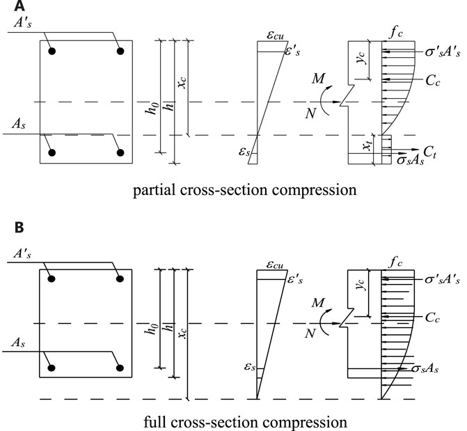
FIGURE 5. Calculation diagram of RECC normal cross-section bearing capacity under small eccentric compression. (A) Partial cross-section compression. (B) Full cross-section compression.
When the cross-section is partially compressed, the stress distribution is similar to that under large eccentric compression. However, the steel bar on the side away from the eccentric force does not yield in tension. Therefore, the calculation formula of axial force and bending moment can be obtained from the equilibrium condition of force. Cc, Ct, and yc can be obtained by Eq. 12, 14 and Eq. 16, respectively.
According to the plane cross-section assumption, the relationship between the stress of the steel bar away from the eccentric force side and the height of the compression zone can be obtained as follows:
If N is known, Eqs 12–16, 20 are substituted into Eq. 18 to obtain the quadratic equation about xc, and the height of the compression zone (xc) can be obtained by solving the equation. Then, the value of xc is substituted into Eq. 19 to obtain the normal cross-section bearing capacity of the RECC column.
2) Compression on full cross-section
When the cross-section is fully compressed, the steel bar away from the eccentric force side is compressed and the compressive stress can be obtained by the plane cross-section assumption.
Therefore, the calculation formula of axial force (N) and bending moment (M) can be obtained from the equilibrium condition of force.
Under the fully cross-sectional compression, the theoretical height of the compressive zone may exceed the actual height of the cross-section. Therefore, the resultant force of the compressive zone can be expressed as
According to the plane cross-section assumption, the strain at any position (y) in the cross-section can be expressed as
Substituting Eq. 25 into Eq. 24, Cc can be obtained as
The distance (yc) from the resultant force of the compression zone to the edge is
Substituting Eqs 3, 26 into Eq. 27, it can be obtained that
in which
If N is known, Eqs 24–28 are substituted into Eq. 22 to obtain the cubic equation about xc, and the height of the compression zone (xc) can be obtained by solving the equation. Then, substitute xc into Eq. 23 to obtain the normal cross-section bearing capacity of the RECC column.
The calculation formula of the normal cross-section bearing capacity of the RECC column under large and small eccentric compression is derived in the previous section. The formulas for calculating the normal cross-section bearing capacity of the column under different pressure zone height (xc) are summarized as follows.
When
When
When
where parameters B, D, F, and G can be calculated by the following equations, respectively.
For eccentric compression members and compression-bending members with given cross-section size, steel bar and material parameters, the ultimate bearing capacity can be obtained under different combinations of axial force and bending moment. Axial force and bending moment under all possible ultimate states are plotted as curves, namely, the N-M interaction curve, which is the envelope of the ultimate state of eccentric compression members.
The former calculation formulas were adopted to investigate the difference of the N-M interaction curves between RECC and RC columns. The values of cross-section size and steel bar and material parameters used are shown in Table 1.
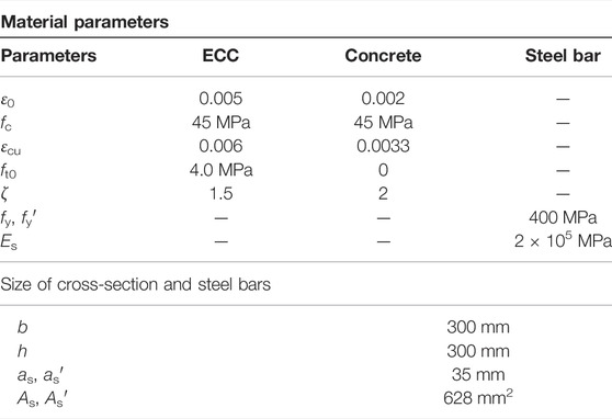
TABLE 1. Values of cross-section size, steel bar, and material parameters.
Figure 6 shows the N-M interaction curves of RECC and RC columns. It can be seen that
1) When the balance failure occurs, the M of the RECC column is larger than that of the RC column and the N of the RECC column is smaller. The reason is that the small eccentric compression failure is similar to the over-reinforced failure in flexural members, and the ECC tensile zone still works, which is equivalent to adding reinforcement in the tensile zone. Therefore, compared with the RC column, it is easier for the RECC column to enter the small eccentric compression state. However, for RECC columns, even if a small eccentric compression failure occurs, it can generally still have good ductility.
2) When large eccentric compression failure occurs, the bearing capacity of the RECC column is larger than that of the RC column under the same axial force. It indicates that the fiber bridging effect of ECC can effectively improve the flexural bearing capacity of the specimen.
3) When small eccentric compression failure occurs, the bearing capacity of the RECC column is smaller than that of the RC column under the same axial force. This is because, under small eccentric compression, the height of the tensile zone is small or even no tensile zone. Therefore, the excellent tensile properties of ECC cannot be well-utilized. The elastic modulus of ECC is low, and the peak compressive strain and ultimate compressive strain are larger than those of concrete. Under the same axial force, to balance the axial force of the section, the height of the compression zone is larger than that of the RC column, resulting in the flexural bearing capacity of the RECC column being smaller than that of the RC column. Because the compressive strength of the two materials is assumed to be the same, the bearing capacity of the two materials under axial compression is the same.
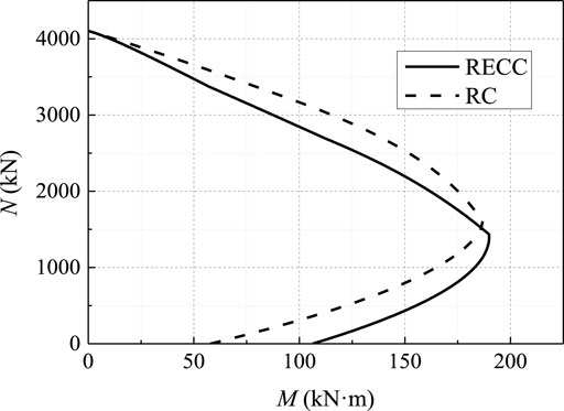
FIGURE 6. N-M interaction curves of RECC and RC columns.
Experiments of seven short columns reported in reference Wu et al. (2017a) were selected to evaluate the accuracy of the above calculation method. The tested columns, including one RC reference column (C1) and six RECC columns (C2∼C7), were loaded under constant axial compression and lateral cyclic loading. All the columns have a cross-section of 300 mm × 300 mm. The schematic diagram of the tested column is shown in Figure 7. The column heights were 500, 600, and 900 mm, and the corresponding shear span-to-depth ratios were 1.42, 1.75, and 2.75, respectively. The longitudinal reinforcement ratio of all the specimens was 1.4%. The test matrix is shown in Table 2, in which the shear span-to-depth ratio, axial force, and transverse reinforcement ratio are taken into account as variables. The detailed mechanical properties of ECC are listed in Table 3, the average yield stress of the longitudinal steel bars is 498 MPa, and the stirrup yield stress is 408 MPa.
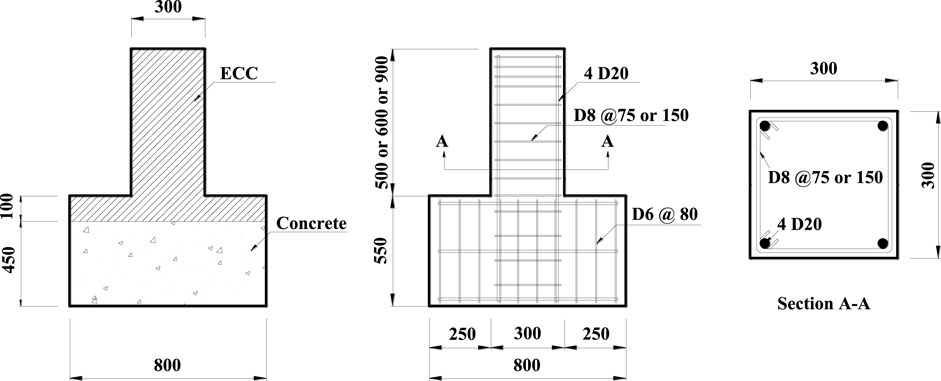
FIGURE 7. Schematic diagram of an RECC column (unit: mm).
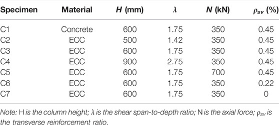
TABLE 2. Test matrix of the columns.

TABLE 3. Mechanical properties of ECC.
The base mat of each specimen was completely fixed while the top of the specimen could be free to move horizontally. In the loading process, the vertical load was first applied on the centroid of the free-end section of the specimen, and then, the transverse load provided by the horizontal actuator (with force and displacement control system) was applied on the top of the column. The detailed test setup and loading configuration are described in reference Wu et al. (2017b).
The analytical and experimental values of load capacity of the RECC columns are shown in Table 4. All the tested columns yielded in the tensile zone at the ultimate load, so the calculation method of the bearing capacity of the cross-section under large eccentric compression was adopted. It can be seen from Table 4 that analytical predictions of the load capacity are in good agreement with the experimental values in columns C3, C4, C6, and C7, whose relative errors are less than 10%. Considering the deviations in experiments, the relative errors between analytical and experimental results are acceptable in engineering applications. However, the analytical load capacity of column C2 is around 19% lower than the experimental values. The reason is that the column exhibited shear failure rather than flexural failure at the ultimate load, and consequently, the force transmission mechanism of the column C2 is different from that of the specimens failed by flexure. Moreover, the obvious principal diagonal cracks led to the inapplicability of the plane section assumption, resulting in calculation error. In addition, the flexural strength of column C5 under high axial compression (N = 700 kN) is seriously underestimated (the test result is 50% higher than the analytical result). This may be attributed to the constraint effect at the end of column due to the loading configuration of the axial compression because the high compression restrained the rotation of the free end of the column.
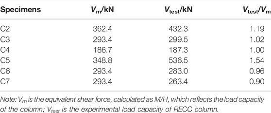
TABLE 4. Comparison of analytical and experimental results.
The comparison above indicates that the proposed equations are able to predict the load capacity of RECC columns whose failure modes are governed by flexure with reasonable accuracy.
The effects of the ultimate tensile strain of ECC, compressive and tensile strength of ECC, yield strength of steel bars, and reinforcement ratio on the N-M interaction curves of RECC columns are investigated by using the proposed calculation equations. The detailed analysis is provided below.
The ultimate tensile strain of ECC has little effect on the sectional bearing capacity of RECC columns. Under small eccentric compression, the steel bars in the tensile zone do not yield, so the ECC at the edge of the tensile zone cannot reach the ultimate tensile strain. The edge of the tensile zone of the RECC column under large eccentric compression generally does not reach the ultimate tensile strain either.
We assume that, when the RECC column failed, the compressive strain at the edge of the compressive zone reached the ultimate compressive strain εcu and the tensile strain at the edge of the tensile zone reached the ultimate tensile strain εtu. The height of the compressive zone can be deduced according to the plane section assumption as follows:
Therefore, as long as the height of the compressive zone (xc) satisfies the inequality
It can be further deduced from Eq. 33 that
Assume that the ultimate compressive strain of ECC (εcu) is 0.005, the strength of the steel bar (fy′) is 450 MPa, the elastic modulus of the steel bar (Es) is 2 × 10⁵ MPa, the height of the RECC column section (h) is 300 mm, and the distance between the position of the steel bar to the edge (as′) is 35 mm. The inequality εtu ≥ 0.026 can be obtained by substituting the parameters above into Eq. 34. The ultimate tensile strain of ECC is generally more than 0.03; therefore, for RECC columns under eccentric compression, as long as the ultimate tensile strain of the prepared ECC is large enough, i.e., εtu satisfies Eq. 34, the edge of the tensile zone generally will not reach the ultimate tensile strain at the ultimate load. It also proves that it is feasible to ignore the effect of ultimate tensile strain of ECC in calculation.
Figure 8 plots the N-M interaction curves of the RECC column with different ECC compressive strength ranging from 30 to 50 MPa. The tensile strength of ECC is 4 MPa. The tensile strength of the longitudinal steel bar is 400 MPa, and the reinforcement ratio is 1.5%.
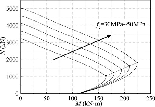
FIGURE 8. N-M interaction curves with different ECC compressive strengths.
It can be seen that the area enveloped by the N-M curve increases with the increase of compressive strength, which indicates that the sectional load capacity increases with the increasing compressive strength. When the axial force N is less than 500 kN, the N-M interaction curves of the RECC columns with different compressive strength are very close. With the increase of axial force N, the difference of the N-M interaction curves gradually becomes more obvious. When the RECC column enters the small eccentric compression state, the sectional load capacity is mainly controlled by the compressive properties of the material. Therefore, the area enveloped by the N-M interaction curve increases with the increase in ECC compressive strength. The N-M interaction curves in the conditions of small eccentric compression are almost paralleled and extend outward with approximately equal intervals. Observing the N and M at the balance failure point of each curve, it can be seen that both axial force and flexural moment increase with the increasing ECC compressive strength. The connecting line of the balance failure point of each column is basically a straight line extending to the upper right corner.
Figure 9 plots the N-M interaction curves of the RECC column with different ECC tensile strengths ranging from 2.0 to 6.0 MPa. The compressive strength of ECC is 40 MPa, and the tensile strength of the steel bar is 400 MPa. The steel bar ratio is taken as 1.5%.
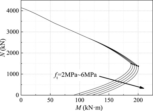
FIGURE 9. N-M interaction curves with different ECC tensile strengths.
In Figure 9, the sectional load capacity increases with the increase of tensile strength, and the spacing of N-M curves is basically equal when the columns fail under large eccentric compression. The N-M interaction curves under small eccentric compression are almost unchanged with the increasing ECC tensile strength. The reason is that the tensile area of the cross-section is large under large eccentric compression, and the tensile strength of ECC can be fully employed, resulting in the increase of flexural strength of RECC columns along with the increasing tensile strength when the axial compression stays. In the case of small eccentric compression, the cross-section is mostly compressed, and the tensile properties of ECC cannot be fully exerted, so the ECC tensile strength has an insignificant effect on the bearing capacity of the section. The balance failure point of each column moves to the lower right, indicating that RECC columns with higher ECC tensile strength enter the state of smaller eccentric compression earlier with the increase of axial force. Owing to the higher ductility of ECC under compression compared with normal concrete and the confinement effect due to the randomly distributed fibers in ECC, the RECC columns are not prone to brittle failure even under small eccentric compression.
Figure 10 plots the N-M interaction curves of RECC columns with different tensile strengths of the steel bar ranging from 300 to 500 MPa. The compressive strength of ECC is 40 MPa, and the tensile strength is 4.0 MPa. The steel bar ratio is 1.5%.
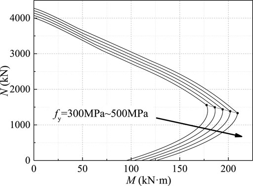
FIGURE 10. N-M interaction curves with different tensile strengths of the steel bar.
The area enveloped by the N-M interaction curve of the RECC column increases under both large and small eccentric compression as seen in Figure 10. It indicates that the sectional load capacity increases with the increasing yield strength of steel bars. Comparing the N and M at the balance failure of each curve, it can be seen that the balance failure point of each column moves to the lower right. It indicates that as the strength of the steel bar increases, the flexural moment increases, but the axial force gradually decreases. This is because the failure under the small eccentric compression is similar to the over-reinforced failure. The increase of the strength of the steel bar makes the member more prone to the “over-reinforced” phenomenon.
Figure 11 plots the N-M interaction curves of RECC columns with different reinforcement ratios of steel bars ranging from 1% to 3%. The compressive strength and tensile strength of ECC is taken as 40 and 4.0 MPa, respectively. The tensile strength of steel bar is 400 MPa.
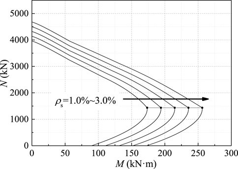
FIGURE 11. N-M interaction curves with different reinforcement ratios.
As shown in Figure 11, the area enveloped by the N-M interaction curve of the RECC column increases under both large and small eccentric compression with the increase of the reinforcement ratio. It indicates that the sectional load capacity increases with the increase of the reinforcement ratio. Comparing the N and M at the balance failure of each curve, it can be seen that the connection line of the balance failure point of each member is almost a horizontal straight line. With the increasing reinforcement ratio, the moment at the balance failure point increases, but the axial force remains unchanged. It indicates that the increase of the reinforcement ratio can not only improve the flexural capacity of the column, but also delay the column into the small eccentric compression state.
In this paper, based on the design theory of the load capacity of eccentric compression columns and the unique constitutive model of ECC, the calculation equations for the sectional load capacity of RECC columns subjected to combined lateral load and axial compression are derived. Strength interaction diagrams showing the axial force-moment (N-M) interaction curves can be constructed by using the proposed calculation equations. A numerical parametric study was then carried out, demonstrating the effects of ultimate tensile strain of ECC, compressive and tensile strength of ECC, yield strength of the steel bar, and reinforcement ratio on the N-M interaction curves of RECC columns. The following conclusions can be drawn:
1) The comparison between the calculated results with the proposed equations and the test results of RECC columns under combined lateral load and vertical axial compression show that the relative errors between calculated and measured load capacities of columns C3, C4, C6, and C7, which were failed by flexure, are less than 10%. It indicates that the proposed equations are able to predict the load capacity of RECC columns whose failure modes are governed by flexure with reasonable accuracy.
2) Theoretical analysis demonstrates that the ultimate tensile strain of ECC has little effect on the sectional bearing capacity of the RECC column. As long as Eq. 34 is satisfied, the edge of the tensile zone on the section of RECC columns can hardly reach the ultimate tensile strain when the specimen fails. Generally, Eq. 34 can be easily satisfied for ECCs whose ultimate tensile strain is more than 0.03, so it is feasible to ignore the effect of ultimate tensile strain of ECC in calculation.
3) The N-M interaction curves of RECC columns are significantly influenced by the compressive strength of ECC under small eccentric compression and moderately affected by the tensile strength of ECC under large eccentric compression. The effects of yield strength of steel bar and reinforcement ratio on the N-M interaction curves of RECC columns are both significant under both small and large eccentric compression. The numerical parametric studies are expected to provide insight on the design principles of RECC columns.
The original contributions presented in the study are included in the article/Supplementary Material, further inquiries can be directed to the corresponding author.
CW: Conceptualization; Writing the original draft; Methodology; Investigation YaS: Review and editing the draft; Investigation YuS: Writing part of the draft; Investigation CJ: Investigation ZP: Supervision.
This study was funded by financial support from the National Natural Science Foundation of China (Grants Number: 52108119), the Natural Science Foundation of Jiangsu Province (Grants No: BK20200376), the Fundamental Research Funds for the Central Universities (Grants No: 2242021R10081), and the Natural Science Foundation of the Jiangsu Higher Education Institutions of China (21KJB560005).
The authors declare that the research was conducted in the absence of any commercial or financial relationships that could be construed as a potential conflict of interest.
All claims expressed in this article are solely those of the authors and do not necessarily represent those of their affiliated organizations, or those of the publisher, the editors and the reviewers. Any product that may be evaluated in this article, or claim that may be made by its manufacturer, is not guaranteed or endorsed by the publisher.
Adnan, A., and Mashshay, S. (2020). Development of Hybrid Ecc Columns Subjected to Concentric and Eccentric Loading. Structures 28, 309–320. doi:10.1016/j.istruc.2020.08.080
Cai, J., Pan, J., and Lu, C. (2018). Mechanical Behavior of ECC-Encased CFST Columns Subjected to Eccentric Loading. Eng. Structures 162, 22–28. doi:10.1016/j.engstruct.2018.02.029
Cai, J., Pan, J., Tan, J., Vandevyvere, B., and Li, X. (2020). Behavior of ECC-Encased CFST Columns under Eccentric Loading. J. Build. Eng., 101188. doi:10.1016/j.jobe.2020.101188
Cui, T., He, H., Zhao, X., and Zhou, D. (2021). Bending Performance Analysis of Precast Composite Beams with Precast Ecc Plate. Structures 33, 986–998. doi:10.1016/j.istruc.2021.04.090
Deng, M., Zhang, H., Liang, X., and Bu, X. (2015). Experimental Study on Seismic Behavior of High Ductile Fiber Reinforced concrete Short Column. J. Build. Struct. 36, 62–69. doi:10.14006/j.jzjgxb.2015.12.008
Doǧangün, A. (2004). Performance of Reinforced concrete Buildings during the May 1, 2003 Bingöl Earthquake in TurkeyBingol Earthquake in Turkey. Eng. Structures 26, 841–856. doi:10.1016/j.engstruct.2004.02.005
Ge, W.-J., Ashour, A. F., Ji, X., Cai, C., and Cao, D.-F. (2018). Flexural Behavior of ECC-concrete Composite Beams Reinforced with Steel Bars. Construction Building Mater. 159, 175–188. doi:10.1016/j.conbuildmat.2017.10.101
Hu, X., Chen, Z., and Bu, X. (2021). Axial Compressive Behavior on Steel Tube-Retrofitted Circular RC Short Columns with Grout under Preload. Structures 33, 2500–2519. doi:10.1016/j.istruc.2021.05.079
Huang, B.-T., Weng, K.-F., Zhu, J.-X., Xiang, Y., Dai, J.-G., and Li, V. C. (2021). Engineered/strain-hardening Cementitious Composites (ECC/SHCC) with an Ultra-high Compressive Strength over 210 MPa. Composites Commun. 26, 100775. doi:10.1016/j.coco.2021.100775
Li, V. C., Stang, H., and Krenchel, H. (1993). Micromechanics of Crack Bridging in Fibre-Reinforced concrete. Mater. Structures 26, 486–494. doi:10.1007/bf02472808
Li, X., Chen, K., Hu, P., He, W., Xiao, L., and Zhang, R. (2020). Effect of ECC Jackets for Enhancing the Lateral Cyclic Behavior of RC Bridge Columns. Eng. Structures 219, 110714. doi:10.1016/j.engstruct.2020.110714
Li, Y.-A., Huang, Y.-T., and Hwang, S.-J. (2014). Seismic Response of Reinforced Concrete Short Columns Failed in Shear. ACI. Struct. J. 111, 945–954. doi:10.14359/51686780
Li, F., Feng, Z., Deng, K., Yu, Y., Hu, Z., and Jin, H. (2019). Axial Behavior of Reinforced PP-ECC Column and Hybrid NSC-ECC Column under Compression. Eng. Structures 195, 223–230. doi:10.1016/j.engstruct.2019.06.010
Li, L. Z, L.-Z., Bai, Y., Yu, K.-Q., Yu, J.-T., and Lu, Z.-D. (2019). Reinforced High-Strength Engineered Cementitious Composite (ECC) Columns under Eccentric Compression: Experiment and Theoretical Model. Eng. Structures 198, 109541. doi:10.1016/j.engstruct.2019.109541
Liu, Jin., Li, X., Zhang, R., and Du, X. (2021). Meso-scale Modelling the post-fire Seismic Behavior of RC Short Columns. Eng. Fail. Anal. 120, 105117. doi:10.1016/j.engfailanal.2020.105117
Maruta, M., Kanda, T., Nagai, S., and Yamamoto, Y. (2005). New High-Rise RC Structure Using Pre-cast ECC Coupling Beam. Jpn. Concrete. Inst. 43, 18–26. doi:10.3151/coj1975.43.11_18
Mishra, D., and Yu, J. (2019). Engineered Cementitious Composites (ECC) - Bendable Concrete for Sustainable and Resilient Infrastructure. Indian Concrete J. 93, 62–69.
Maalej, M., Li, V. C., and Hashida, T. (1995). Effect of Fiber Rupture on Tensile Properties of Short Fiber Composites. J. Eng. Mech. 121, 903–913. doi:10.1061/(asce)0733-9399(1995)121
Montesinos, P., and Gustavo, J. (2005). High-Performance Fiber-Reinforced Cement Composites: An Alternative for Seismic Design of Structures. ACI. Struct. J. 102.
Pan, Z., Zhu, Y., Qiao, Z., and Meng, S. (2020). Seismic Behavior of Composite Columns with Steel Reinforced ECC Permanent Formwork and Infilled Concrete. Eng. Structures 212, 110541. doi:10.1016/j.engstruct.2020.110541
Qiao, L., Li, L., Li, B., and Yu, J. (2021). Prediction on the Flexural Deflection of Ultra-high Strength Rebar Reinforced Ecc Beams at Service Loads. Structures 33, 246–258. doi:10.1016/j.istruc.2021.04.050
Qin, F., Zhang, Z., Yin, Z., Di, J., Xu, L., and Xu, X. (2020). Use of High Strength, High Ductility Engineered Cementitious Composites (ECC) to Enhance the Flexural Performance of Reinforced concrete Beams. J. Building Eng. 32, 101746. doi:10.1016/j.jobe.2020.101746
Qudah, S., and Maalej, M. (2014). Application of Engineered Cementitious Composites (ECC) in interior Beam-Column Connections for Enhanced Seismic Resistance. Eng. Structures 69, 235–245. doi:10.1016/j.engstruct.2014.03.026
Paulay, T. (2005). Experimental Study on Seismic Behavior of High-Performance Fiber-Reinforced Cement Composite Coupling Beams. Sj 102, 909–912. doi:10.14359/13541
Li, V. C., and Leung, C. K. Y. (1992). Steady-State and Multiple Cracking of Short Random Fiber Composites. J. Eng. Mech. 118, 2246–2264. doi:10.1061/(asce)0733-9399(1992)118
Li, V. C., Leung, C. K. Y., Dhanada, K., Yu, J., and Zhang, D. (2019). Indian Concrete Journal: Special Issue on Sustainable Engineered Cementitious Composites (ECC)
Li, V. C., Wang, S., and Wu, C. (2001). Tensile Strain-Hardening Behavior of Polyvinyl Alcohol Engineered Cementitious Composite (PVA-ECC). Mj 98, 483–492. doi:10.14359/10851
Wang, L., Yin, S., and Hua, Y. (2021). Flexural Behavior of BFRP Reinforced Seawater Sea-Sand Concrete Beams with Textile Reinforced ECC Tension Zone Cover. Construction Building Mater. 278, 122372. doi:10.1016/j.conbuildmat.2021.122372
Wang, Z. (2008). A Preliminary Report on the Great Wenchuan Earthquake. Earthq. Eng. Eng. Vib. 7, 225–234. doi:10.1007/s11803-008-0856-1
Wu, C., Pan, Z., Jin, C., and Meng, S. (2020). Evaluation of Deformation-Based Seismic Performance of RECC Frames Based on IDA Method. Eng. Structures 211, 110499. doi:10.1016/j.engstruct.2020.110499
Wu, C., Pan, Z., Kim, K.-S., and Meng, S. (2017b). Theoretical and Experimental Study of Effective Shear Stiffness of Reinforced ECC Columns. Int. J. Concr Struct. Mater. 11, 585–597. doi:10.1007/s40069-017-0219-2
Wu, C., Pan, Z., and Meng, S. (2016). Cyclic Constitutive Model for Strain-Hardening Cementitious Composites. Mag. Concrete Res. 68, 1133–1142. doi:10.1680/jmacr.15.00052
Wu, C., Pan, Z., Su, R. K. L., Leung, C. K. Y., and Meng, S. (2017a). Seismic Behavior of Steel Reinforced ECC Columns under Constant Axial Loading and Reversed Cyclic Lateral Loading. Mater. Struct. 50, 78. doi:10.1617/s11527-016-0947-9
Xu, L.-Y., Huang, B.-T., Li, V. C., and Dai, J.-G. (2022). High-strength High-Ductility Engineered/Strain-Hardening Cementitious Composites (ECC/SHCC) Incorporating Geopolymer fine Aggregates. Cement and Concrete Composites 125, 104296. doi:10.1016/j.cemconcomp.2021.104296
Yang, E.-H., Wang, S., Yang, Y., and Li, V. C. (2008). Fiber-Bridging Constitutive Law of Engineered Cementitious Composites. Act 6, 181–193. doi:10.3151/jact.6.181
Yuan, F., Chen, M., and Pan, J. (2019). Experimental Study on Seismic Behaviours of Hybrid FRP-Steel-Reinforced ECC-concrete Composite Columns. Composites B: Eng. 176, 107272. doi:10.1016/j.compositesb.2019.107272
Yuan, F., Chen, M., Zhou, F., and Yang, C. (2018). Behaviors of Steel-Reinforced ECC Columns under Eccentric Compression. Construction Building Mater. 185, 402–413. doi:10.1016/j.conbuildmat.2018.07.100
Yuan, F., Pan, J., and Leung, C. K. Y. (2013). Flexural Behaviors of ECC and concrete/ECC Composite Beams Reinforced with basalt Fiber-Reinforced Polymer. J. Compos. Constr. 17, 591–602. doi:10.1061/(asce)cc.1943-5614.0000381
Zhang, J., Leung, C. K. Y., and Gao, Y. (2011). Simulation of Crack Propagation of Fiber Reinforced Cementitious Composite under Direct Tension. Eng. Fracture Mech. 78, 2439–2454. doi:10.1016/j.engfracmech.2011.06.003
Zhang, Y., Deng, M., and Dong, Z. (2019). Seismic Response and Shear Mechanism of Engineered Cementitious Composite (ECC) Short Columns. Eng. Structures 192, 296–304. doi:10.1016/j.engstruct.2019.05.019
Zhang, Z., Qin, F., Ma, H., and Xu, L. (2020a). Tailoring an Impact Resistant Engineered Cementitious Composite (ECC) by Incorporation of Crumb Rubber. Construction Building Mater. 262, 120116. doi:10.1016/j.conbuildmat.2020.120116
Zhang, Z., Yang, F., Liu, J.-C., and Wang, S. (2020b). Eco-friendly High Strength, High Ductility Engineered Cementitious Composites (ECC) with Substitution of Fly Ash by rice Husk Ash. Cement Concrete Res. 137, 106200. doi:10.1016/j.cemconres.2020.106200
Zhang, Y., Deng, M., Li, T., and Dong, Z. (2021). Strengthening of Flexure-Dominate RC Columns with ECC Jackets: Experiment and Analysis. Eng. Structures 231, 111809. doi:10.1016/j.engstruct.2020.111809
Zhang, Z., Liu, S., Yang, F., Weng, Y., and Qian, S. (2021). Sustainable High Strength, High Ductility Engineered Cementitious Composites (ECC) with Substitution of Cement by rice Husk Ash. J. Clean. Prod. 317, 128379. doi:10.1016/j.jclepro.2021.128379
Keywords: engineered cementitious composites (ECC), column, eccentric compression, sectional load capacity, axial load-moment interaction curve
Citation: Wu C, Su Y, Sun Y, Jin C and Pan Z (2022) Sectional Analysis of Reinforced Engineered Cementitious Composite Columns Subjected to Combined Lateral Load and Axial Compression. Front. Mater. 9:869835. doi: 10.3389/fmats.2022.869835
Received: 05 February 2022; Accepted: 15 February 2022;
Published: 14 April 2022.
Edited by:
Zhigang Zhang, Chongqing University, ChinaReviewed by:
Bo-Tao Huang, Hong Kong Polytechnic University, Hong Kong SAR, ChinaCopyright © 2022 Wu, Su, Sun, Jin and Pan. This is an open-access article distributed under the terms of the Creative Commons Attribution License (CC BY). The use, distribution or reproduction in other forums is permitted, provided the original author(s) and the copyright owner(s) are credited and that the original publication in this journal is cited, in accordance with accepted academic practice. No use, distribution or reproduction is permitted which does not comply with these terms.
*Correspondence: Chang Wu, Y2hhbmd3dUBzZXUuZWR1LmNu
Disclaimer: All claims expressed in this article are solely those of the authors and do not necessarily represent those of their affiliated organizations, or those of the publisher, the editors and the reviewers. Any product that may be evaluated in this article or claim that may be made by its manufacturer is not guaranteed or endorsed by the publisher.
Research integrity at Frontiers
Learn more about the work of our research integrity team to safeguard the quality of each article we publish.