 Anatoly Koptelov
 Jonathan P-H. Belnoue
 Ioannis Georgilas
 Stephen R. Hallett
 Dmitry S. Ivanov
- 1Bristol Composites Institute, University of Bristol, Bristol, United Kingdom
- 2Department of Mechanical Engineering, University of Bath, Bath, United Kingdom
This paper explores the application of a novel adaptive consolidation sensor framework for the characterisation of composite precursors. The designed framework develops material-driven test programmes in real-time and defines robust material models for the studied composite precursor. The proposed approach allows to remove any subjective judgement about the material behaviour and to reduce human involvement at the experimentation stage. The proposed framework along with the developed data transfer/acquisition hardware setup was put to the test within several characterisation exercises. Two different material systems were tested. The output of the proposed testing method—model and properties for the tested materials—is compared with the results of the conventional deterministic characterisation tests.
1 Introduction
The production of composites has its own challenges, including a possible negative impact on the environment. The manufacture of a part made of carbon fibres requires 14 times more energy than its steel counterpart (Das 2011). The production of defective composite parts contributes greatly to the additional waste generation. The existing methods for recycling of composites through the controlled pyrolysis process are energy demanding as well and are currently unable to be applied at scale. To lower the energy consumption and make the manufacturing process more sustainable, it is important to reduce the number on unsuccessful manufacturing trials and defective composite parts.
The complexity of composites manufacturing stems from the nature of composite precursors—the combination of loosely-joined fibre network and liquid viscous resin—often heterogenous and enhanced with tougheners or functional additives. The resultant system is compliant, deforms irreversibly, exhibits almost negligible resistance to axial compressive stresses and has a multitude of flow/deformation mechanisms. This makes precursors prone to defects at all stages of the composites manufacturing process—from the deposition to cure.
One of the fundamental processes, universal almost for the entire range of composites manufacturing methods, is consolidation, where a composite precursor undergoes compression to engage plies in contact, squeeze out volatiles, control fibre volume fraction and thickness, obtain near-net component shapes, etc. Material response in consolidation arises from a complex interaction of various deformation mechanisms (i.e. the internal or percolation flow of resin (Hubert et al., 1999), flow of fibrous suspensions (Paterson et al., 2019), densification of reinforcement (Haghdan, Tannert, and Smith 2015), (Castellanos et al., 2020), relative movement of plies (Lightfoot, Wisnom, and Potter 2013), and others). Different forms of these mechanisms take place at different structural scales and often occur in parallel or exhibit transition from one state to another. There is a vast variety of deformation mechanisms and physical models of resin flow occurring on macro and micro levels of the material: shear flow of inter-ply resin ligaments, resin filling between tows, fibrous tapes, and macroscopic sheets of preforms (Groves 1989; Kaprielian and O’Neill 1989; Rogers 1989; Shuler and Advani 1996), percolation resin flow through fibre network (Timothy G. Gutowski et al., 1987b; T. G Gutowski and Dillon 1992; T. G. Gutowski et al., 1987a), the deformation of the reinforcement (Bréard et al., 2003; Somashekar, Bickerton, and Bhattacharyya 2007), etc. The co-existence of different deformation phenomena and the transition from one mode to another was reported in a number of studies (Hubert and Poursartip 2001a), (Ivanov et al., 2013), (Nixon-Pearson et al., 2017). Characteristic features for both percolation (resin bleeding) and shear (ply squeezing) flows were reported by Belnoue et al. (J. P. H. Belnoue et al., 2016).
The co-existence of many deformation modes requires special attention when assessing precursors. Process optimisation hinges on the reliability of material models. Yet, the details of flow process occurring at ply or sub-ply scales are often difficult to observe and examine directly. For this reason, in the conventional experimentation the dominant deformation mechanism is often assumed prior to the experiment and the testing program is designed in accordance with that assumption. Such approach introduces bias into the testing which might affect the validity of the characterisation outcome within a different set of processing conditions.
There are many strategies to identify material models’ parameters depending on the assumed flow type and the studied phenomenon. Characterisation of glass fibre textiles by a multiplicative phenomenological material model was performed by (Kelly 2011) in a series of monotonic compression tests at various rates (at very slow and very fast rates as referred to by the author) with the subsequent load relaxation. The characterisation of toughened prepregs under processing conditions consistent with different types of composite manufacturing—automated fibre placement (low temperature/moderate pressure), autoclave consolidation (high temperature/high pressure), debulking (wide range of temperatures/low pressure) was conducted by (Nixon-Pearson et al., 2017). Ramp-dwell displacement controlled tests for separating viscous and elastic contributions of fibrous and resin components were conducted by (P Hubert and Poursartip 2001b). To observe various rheological behaviours of shear flow, was performed by (Engmann, Servais, and Burbidge 2005) performed a series of characterisation tests with different plate closure speed/rate/relaxation conditions. Creep behaviour of carbon fibre prepreg at various strain levels was studied by (Almeida et al., 2018). The shear-percolation transitional model, called DefGen ProToCoL (J. P.H. Belnoue et al., 2016), suggested a bespoke testing methodology and exhibited high adaptivity to various materials and consolidation cases. Yet, there is currently no universal testing approach that provides differentiation between the flow modes and guarantees robust assumption-free parameter identification. This creates ground for subjective judgement on the nature of underlying processes and significant errors in process analysis.
Robust and relevant material model allows to achieve target thickness of a composite part and prevent defects formation within the specified processing conditions (J. P.H. Belnoue et al., 2018). (Koptelov et al., 2022) demonstrated that the conventional testing poses a high risk of introducing fundamental error in results interpretation. A theoretical framework to tackle this problem was suggested and validated in virtual space. Plain experimental programmes, e.g. series of monotonic loading tests, could be insufficient for a material’s characterisation. The derived model might perform deceptively well within data provided for training but completely fail to adapt to changing processing conditions. The main idea of the new framework is to use autonomous testing, where various candidate models compete in a real-time interrogation of a material. All the models are constantly fitted to available experimental data and prioritised based on the quality of fit. At every testing stage, the load trajectory (load, load rate, ramp type) is selected to maximise the difference between the two best models. The process continues until a satisfactory match with all the data is obtained. Virtual testing based on these principles has been shown to successfully identify various shear, percolation and synthetic (i.e., DefGen) models hidden from an interrogation module in a “black box”.
This paper continues the work done by (Koptelov et al., 2022) by implementing the theoretical framework into a full prototype combining standard testing equipment, bespoke consolidation rig, and autonomous module for human-free load trajectory navigation. The paper starts with a summary of key features and principles of the Autonomous Testing Framework (ATF). This system is then applied to well-studied materials with transitional behaviour, such as toughened prepregs (Nixon-Pearson et al., 2017; Matveev et al., 2019), to acquire an independent assessment of most suitable models. The consistency of load trajectories produced by the ATF are explored in a wide range of tests with varying test settings, such as load curve constraints, test duration etc. Eventually, the ATF is discussed as a tool to minimise the efforts required for testing complex systems and obtaining reliable unbiased material assessment.
2 The Concept of Autonomous Testing Framework
The main purpose of the ATF is to build a testing programme in real time and in a responsive manner based on the continuously supplied data on thickness evolution of a tested sample. The detailed algorithm of the consolidation sensor is shown in Figure 1. It is assumed that the compacted material can be adequately described by one of the consolidation models from a pre-defined library (Koptelov et al., 2022), but there is no prior knowledge about what flow type will dominate and appear to be most adequate for the material description. This library contains models of resin flow in the form of ordinary differential equations. After the end of each load step, the framework challenges all consolidation models from the library (which are referred to as candidate models) to analyse the incoming compaction response from the testing machine. The performance of each model is assessed for its ability to fit the experimental compaction curve. Based on the prediction of two best performing candidates the load schedule for the next step is generated and is passed to the testing machine. The designed loading programme aims at distinguishing between best performing candidate models. The primary driver for such algorithm is not to determine the material properties per se, though this is also achieved as a by-product of the process, but to select the right flow mode. Such an approach is free from bias towards any of the consolidation models. Thus, the framework is only limited by the diversity of the candidate models in the consolidation library. Moreover, the library can be expanded by adding new compaction models if new material is needed to be considered.
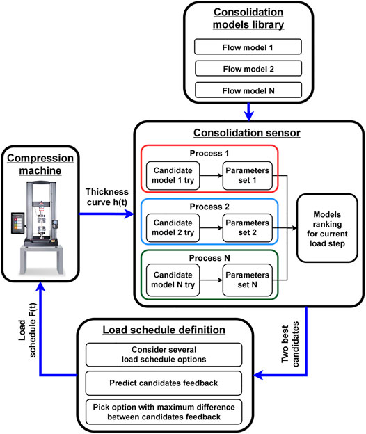
FIGURE 1. Detailed algorithm of the ATF.
In its current form the library includes compaction models that in their general forms are governed by a differential equation of the following form:
where F(t, h) is a function containing the history of the evolution of the applied pressure, h is the thickness,
For instance, for the DefGen model material parameters represent the following: parameter a relates to the flow behaviour and defines whether the fluid is dilatant, Newtonian or shear-thinning; parameter b represents an energy barrier controlling the ability of resin to flow through the fibre network; and lastly, parameter k is related to the size of a fibre in relation to the unit cell size (J. P. Belnoue et al., 2021).
The main focus of the proposed study was on the development of new testing methodologies for composite characterisation rather than the development of specific models for the considered materials. The physics, assumptions and limitations of any particular flow models were beyond the scope of this manuscript. However, every model used in this study is well-known and was previously trialled and verified experimentally for the similar material types. The flow models present in the library are consistent with previous work (Koptelov et al., 2022). The properties of the laminate are defined by the flow and deformation characteristics of the individual plies. The models deployed in the library are used to deduce the properties of a unidirectional ply and not the effective properties of the tested laminate. One of the critical parameters distinguishing various configurations is the aspect ratio of initial with to thickness, which is explicitly included in all the models. A summary of all the models, material parameters, and abbreviations used can be found in Table 1. The reader is asked to refer to (Koptelov et al., 2022) for the full mathematical representation of the models considered.
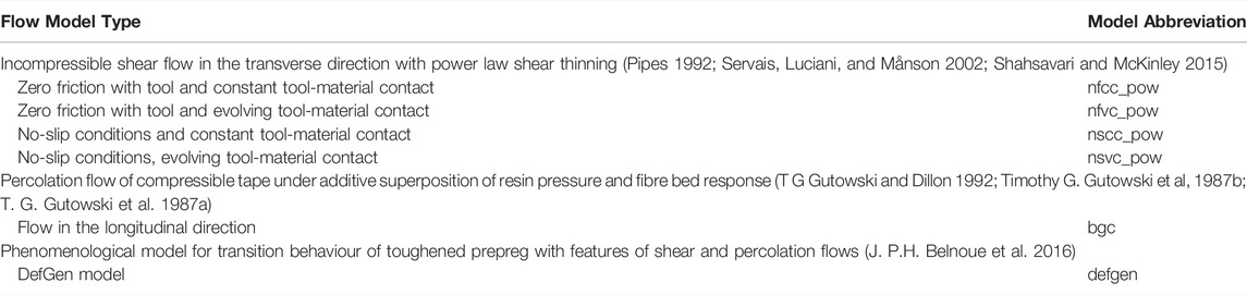
TABLE 1. Candidate flow models used in the study.
3 Implementation of the ATF
The experimentation with closed-loop feedback on real materials imposes a number of technical challenges. The adaptive consolidation sensor must provide a continuous data exchange between the analytical module of the ATF and the testing machine. The applied loading programme must be defined by the ATF and supplied to the compression machine prior to the start of the next load step. The thickness evolution history from the experiment must be received by the ATF at the end of each load step for post-processing and load programme definition. The input for the testing machine should include applied load, load rate, and load type (monotonic or ramp-dwell).
The acquisition of the experimental data from the testing rig should not be interrupted at any point of the test. It means that the experiment cannot be stopped or put on pause while the framework processes the compaction results, despite the fact that the load command for the next step may not be formulated yet. For this reason, the data processing time must be minimised to reduce the delay between receiving the input and defining the load trajectory for the next step.
The conceptual design of the autonomous characterisation testing setup is presented in Figure 2.
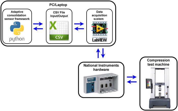
FIGURE 2. Autonomous real-time testing setup overview.
The proposed testing system is composed as follows:
• The adaptive testing framework is located on the host (PC/laptop) external to the testing machine. As described before, the framework “waits” for the compaction data to be passed from the compression machine at the end of each load step. The testing machine cannot proceed to the following load step until the commanding load schedule is received back from the framework. For the real-time experimentation, the test must continue during the processing of information from the previous step. Therefore, there is a need for an inter-step waiting time while the framework analyses the incoming response and decides the magnitude and direction of the next load increment load. The chosen approach is to keep the load at a steady level as shown in Figure 3 (pink “dwell” region). Changing the load level during the processing stage may pose a safety threat, as the data analysis may take more time than expected. This scenario can lead to loading above the acceptable level and possible equipment damage.
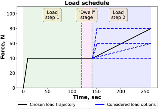
FIGURE 3. “Dwell” stage between load steps required for data processing.
Although the compaction data is still received and used by the framework during the “dwell” stage, it is necessary to minimise the time delay. Excessive duration of dwell stages may affect the path of the load curve, because the framework’s algorithm might find a different set of favourable candidate models for the resulting compaction dataset. Therefore, in order to facilitate a quick transition between load steps, all candidate models are processed in parallel within a multiprocessing approach (see Process 1, … , Process N shown in Figure 1).
• The autonomous real-time experimentation was performed on a servohydraulic Instron 8,872 machine instrumented with heater platens. The setup used for testing is shown in Figure 4. The characterisation tests were conducted in load-controlled mode, as the closed-loop nature of the experimentation requires sending load commands based on the material response. To provide a continuous data exchange between the framework and the test rig, the main requirement for the universal testing machine used in this study was to have an analog interface for the control and feedback signals. The lower heater platen was attached to an external cantilever beam load cell (1 kN capacity) which was mounted on the angle plate fixture. To provide the required temperature conditions, both platens had thermocouples attached to them that allowed to control the temperature accurately.
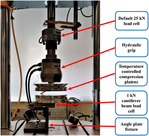
FIGURE 4. Compression heater platens, cantilever load cell, fixture.
• The external host (PC/laptop) was connected to the compression test machine through the data acquisition hardware. Its main purpose is to control the synchronisation, timing, and data transfer between the framework and the test rig. During an experiment, it sends load schedule commands from the consolidation sensor to the Instron and receives the experimental data (displacement/load/time) back. The hardware used in this study was a National Instruments data acquisition chassis cDAQ-9174 with input NI 9201 and output NI 9263 modules. This was connected to the analog input/output ports of the Instron’s data logger and to the USB port of the external host.
• Finally, the data acquisition setup was managed by a custom framework implemented in the LabVIEW environment (NationalInstruments 2003). This provides continuous data exchange between the consolidation sensor and the data acquisition hardware (and, consequently, the test rig) through the exchange of csv (comma separated value) files, as shown in Figure 2. This framework is located on the same PC/laptop as the adaptive consolidation sensor.
The LabVIEW data managing framework was designed in the form of a state machine. The proposed scheduling architecture allows to implement complex decision-making behaviour through the system of states and state transitions. Each state has its own designated function. For instance, it could be sending data to the compression machine, writing results file, finishing the test etc. The transition from one state to another is performed when trigger events occur. A trigger event could be a manual command (pressing the “Start” button) or a condition fulfilment (the designated time for load step is over, the experimentation is completed, etc.). The principal scheme of the consolidation framework (Python)—LabVIEW state machine—Instron universal testing machine is shown in Figure 5.

FIGURE 5. LabView state machine overview.
The State 1 “Initialise” is executed prior to the experiment. Its purpose is to specify the initial settings for the test (number/duration of load steps, load magnitude). Then, the system is transferred to the State 2 “File search”. At this state the LabView framework is searching for the initial load step commands from the consolidation sensor. As soon as the load schedule is formulated, the next state is activated, and the characterisation test is commenced. The rest of the test is conducted entirely in autonomous mode. The load commands are sent to the compression machine within the State 3 “Load sending”. Concurrently, the machine’s feedback with the compaction data (time/displacement/load) is received back during this state. After the end of each load step the system is switched to the State 4 “Write file”, when the experimental data is exported in an output csv file. This file, in turn, serves as an input for the adaptive consolidation sensor framework. While waiting for the ATF to process the incoming batch of the experimental data, the LabView framework keeps the load level at steady level within the State 5 “Dwell search”. When the command for the next load step is formulated, the system switches back to the State 3. In the end of the experimentation after the last load step is performed, the system automatically unloads the test specimen within the State 6 “Test Finish”.
4 Experimentation
4.1 Studied Materials
The real-time characterisation testing was performed for different fibrous material systems. These materials tend to spread transversely as the plies are squeezed from underneath the area under compression. Hence, all test specimens were laid up in a cruciform configuration to allow plies to remain in contact. For the sake of consistency with previous work (Koptelov et al., 2022), the geometry and the layup of the cross-ply specimen remained unchanged. The compaction area of the cruciform specimens was chosen to be 15 × 15 mm.
The following material systems were used:
• IMA/M21 toughened prepreg with a nominal cured ply thickness of 0.184 mm and 59.2% fibre volume fraction (HEXCEL Corporation 2015). All specimens were laid-up in a 16 plies cross-ply (CP) configuration [90/0]8 with a total thickness of ∼3.3 mm. The test sample is shown in Figure 6A.
• IM7/8552 prepreg (HEXCEL Corporation 2020). The test sample is shown in Figure 6B. The prepreg material has a nominal cured ply thickness of 0.131 mm and 57.7% fibre volume fraction. Like IMA/M21 test batches, all specimens were laid-up in 16 plies cross-ply configuration [90/0]8 with a total thickness of ∼2.17 mm.
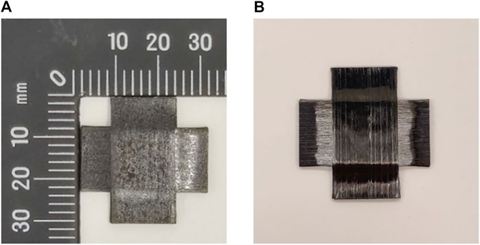
FIGURE 6. (A)—IMA/M21 test sample; (B)—IM7/8552 test sample.
The choice of tested material systems was made due to their well-studied complex transitional flow behaviour under processing conditions (Nixon-Pearson et al., 2017; Matveev et al., 2019). The temperature for the experimentation for all specimens was set at 60°C (temperature where both shear and percolation flows may occur explicitly in case of prepreg materials (Ivanov et al., 2013), (Nixon-Pearson et al., 2017)).
4.2 ATF Test Parameters
There are several settings of the consolidation sensor framework which can affect the load routing of the resulting testing programme:
• The initial load step. Its load trajectory (monotonic or ramp-dwell), amplitude, and duration are defined manually by the researcher at start of a test when no prior information from the material is available. It may be expected that the initial step may have some influence on test progression.
• Load step parameters. The number of the considered load step options (see Figure 1), the duration of a single load step, the maximum possible load amplitude within one load step, the total number of load steps.
Different test settings were explored within the experimentation on the two types of materials. The goal was to investigate the framework’s output (resulting loading programme) and candidate models ranking in dependence on the different load/strain rates and reached compaction level of the studied material. The variation in ATF test settings (initial load step, maximum load amplitude within one step, number of load steps) was defined with the goal of incorporating possible processing conditions close to various manufacturing methods such as AFP deposition, debulking, consolidation in autoclave etc. The settings were chosen to be consistent with the overall experimentation within the study in a sense of the maximum load, load rate, and the number of load steps. The summary of all performed real-time tests is presented in Table 2.
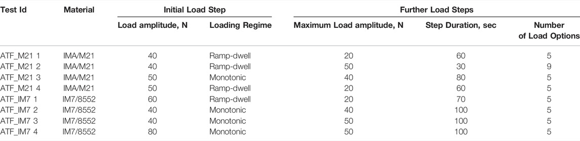
TABLE 2. Explored test settings for the real-time testing of IMA/M21, IMA/M21 material.
Both monotonic and ramp-dwell initial load step options with the load amplitude variation between 40 and 50 N were explored for testing of IMA/M21 material samples. The load amplitude within the following steps was varied between 20 and 50 N. The duration of a single step was specified in the range 30–80 s. The framework had a choice of five different load options at the end of each load step (one dwell option, two ramp-dwell options, two monotonic options). The testing procedure of IM7/8552 material followed a similar pattern. Both monotonic and ramp-dwell initial load step options with the load amplitude variation comprised between 40 and 80 N were explored. For further load steps the load amplitude was varied between 20 and 50 N for the duration of 70 and 100 s. The number of possible load options remained the same (5 options) as in the previous testing for IMA/M21 material.
4.3 Deterministic Loading Programmes
To estimate the efficiency of the proposed approach, the characterisation tests with deterministic loading programmes (predefined before experiment) were also performed. The material models developed from the real-time and deterministic tests were put to the test at the validation stage.
Deterministic experimental programmes were designed in a way to incorporate a wide variety of pressure levels, pressure rates in various loading modes—slow monotonic and ramp-dwell regimes. Some programmes were conventional ramp-dwell schedules as used in the literature (Nixon-Pearson et al., 2017). Another batch of programmes were inspired by the outcomes of ATF testing conducted in virtual space (Koptelov et al., 2022). In this case load slowly reaches an intermediate level, dwells, and then keeps raising again. The set of all considered load schedules is presented in Figure 7.
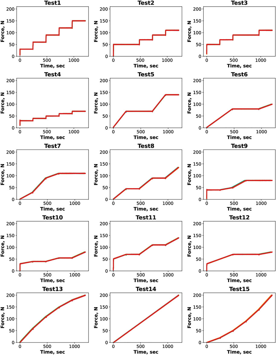
FIGURE 7. Deterministic loading programmes.
An ideal characterisation programme should cover a maximum range in the space of load/load rate/strain, so that the material is exposed to various loading regimes at different stages of deformation. This would test various modes of behaviour, such as elastic, viscoelastic, viscous. The designed test programmes were not aimed to reproduce any particular processing conditions specific to existent manufacturing methods as it is not possible to replicate every loading scenario specific to different manufacturing methods within a limited set of tests. The end goal was to showcase the advantage of certain loading schedules over others in terms of the required number of tests for the robust identification of material models as well as the necessity of multiple experiments to get a data-rich compaction response of the material.
Several characteristic load patterns were considered within this study: load ramp-dwell (Tests 1–4), monotonic load rise-dwell (Tests 5–8), monotonic load rise only (Tests 13–15), and the combined mode (Tests 9–12), which included all of the abovementioned regimes. Every loading schedule was comprised of five load steps of 240 s each. For a ramp-dwell regime the fastest load application rate was 0.1 MPa/s and was followed by dwell intervals of different duration. In case of a monotonic regime load rate varied between 1.8e-4 and 1.3e-3 MPa/s. An incremental compression force within one load step was specified in a range from 10 to 70 N. The range of load values/rates, load steps numbers/duration was inspired by previously conducted work for DefGen model characterisation (J. P.H. Belnoue et al., 2016; Matveev et al., 2019; Nixon-Pearson et al., 2017; Mario A. Valverde et al., 2021; J. P. Belnoue et al., 2021).
It must be emphasised, the volume of the deterministic test programme for the IM7/8552 material was reduced to the first eight tests shown in Figure 7 for the sake of lowering the number of experimental trials. The duration of each load step in these tests was reduced from 240 to 120 s (hence, causing a reduction of the overall time of the test).
Ply thickness evolution was retrieved by measuring the compression machine’s crosshead displacement for both deterministic and real-time ATF testing experimentation. Calibration tests within the same loading programme but without a specimen were carried out for the deterministic tests only in order to estimate compression rig’s compliance. For the considered rig and test parameters, the contribution of machine’s compliance was found to be negligible and not affected by the load rate. Hence, the thickness could be reliably deduced from the displacement reading of the machine.
5 Results
5.1 Real-Time ATF Testing
The resulting real-time test programmes along with the corresponding compaction response for all considered material systems are presented in Figure 8.
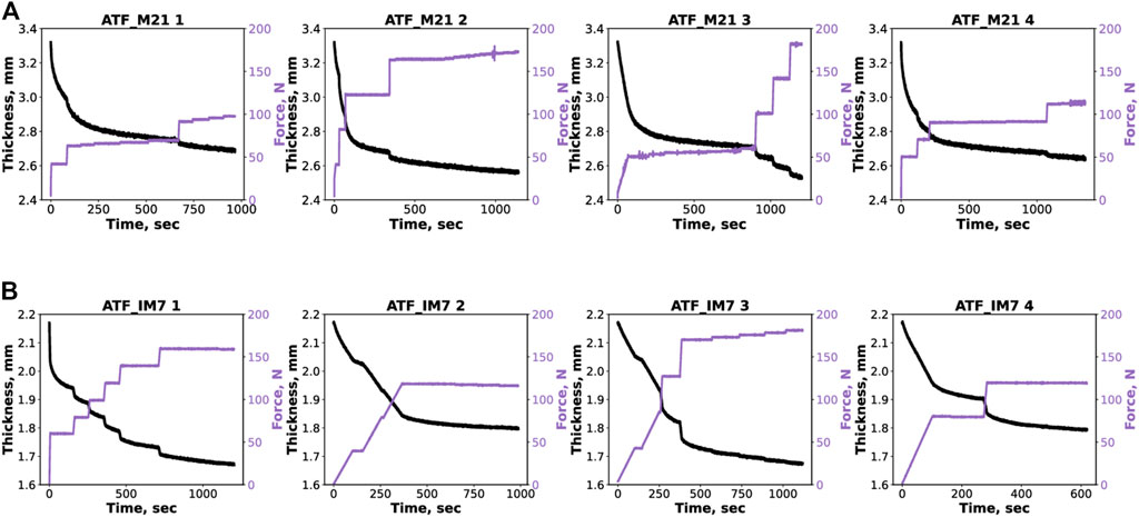
FIGURE 8. Real-time material testing. Resulting loading programmes and compaction curves for the real-time experimentation, (A) IMA/M21 prepreg, (B) IM7/8552 prepreg.
All resulting test programmes for IMA/M21 material showed a similar trend. The load reached a certain level (∼50 N for tests ATF_M21 1, 3 and ∼100 N for tests ATF_M21 2, 4) in one to three steps and held steady. Within the last three to four load steps the load started to raise again. Closer to the end of the test ATF_M21 2 (at ∼1,000 s of the test) a local spike in the load feedback can be observed. Such effect is the result of the instability in the load PID control. As it can be seen from the compaction curve (black line), the amplitude of the load spike was not significant enough to affect the thickness feedback. Due to the high-resolution of the load cell, such phenomena are rare and does not cause a detrimental effect on the experimental results. The shape of the resulting loading programmes for IM7/8552 material was shown to be consistent for all performed tests as well. Upon reaching a certain level (120 N for tests ATF_IM7 2, 4 and ∼160–170 N for tests ATF_IM7 1, 3), the load held steady until the end of the experiment. An interesting observation is that the framework proposed both monotonic and ramp-dwell load step options (for the steps following the initial one) for the test ATF_IM7 3, which was not observed in the previous experimentation.
To illustrate the framework’s decision-making routine, the sequence of the parameter extraction steps for a chosen test (ATF_M21 3) is shown in Figure 9. Each graph is complemented with the preliminary candidate models ranking and the processing time required by the framework. The ranking is based on the root mean square error between the candidate models’ feedback and actual data. Upon the completion of the initial step, the framework defined the shear and percolation models as the top two candidates. The shear model was successfully reflecting the material’s compaction response up to the second stage of the load ramp within the last three load steps (red curve, load step 7). After the change in the load pattern, the shear model struggled to output a robust prediction and showed a significant deviation from the material’s thickness evolution curve. An interesting observation is that the framework defined a non-optimal set of material parameters for the DefGen model (purple compaction curve) after the first load step. The model demonstrated a significant offset from the experimental data and was ranked fourth. The model’s parameter set was corrected within further load steps and two best candidates (DefGen and percolation) were defined in the end of the test. Such effect shows the advantage of the approach, where the model definition is refined at each load step based on the previously obtained results.
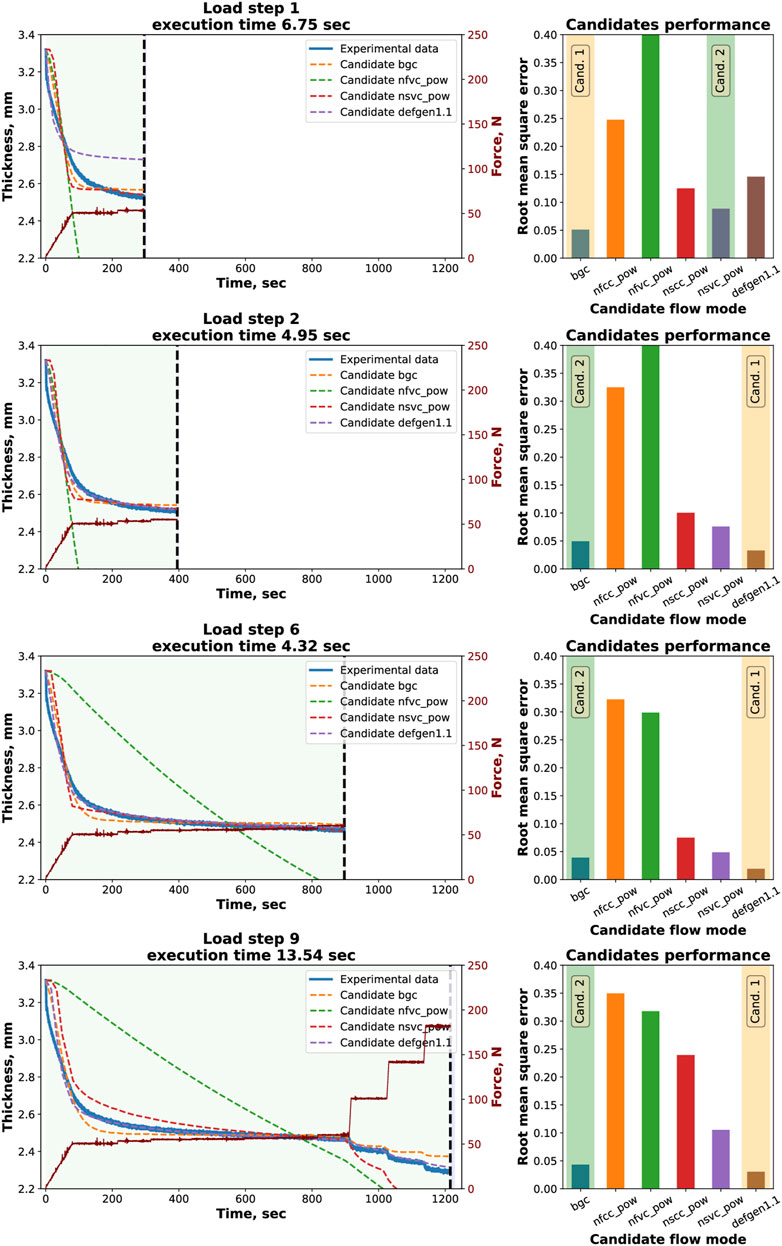
FIGURE 9. IMA/M21 real-time experimentation step by step routine. Green region—all previously received data. Blue region (on the right from the vertical black dashed line)—required processing time.
The results of the models’ training for all four tests on IMA/M21 prepreg are presented in Figure 10A (where “rmse” stands for root means square error). For the sake of clarity, only four candidates are shown (along with the experimental data) on the graphs. It can be seen that the second-best candidate (percolation, “bgc”) showcased a very close output in comparison with the DefGen model with only a slight deviation in the value of the final thickness. The shear model (“nscc_pow”) also demonstrated a good fit until the point of the load trend changed in the second half of the test (as discussed earlier).
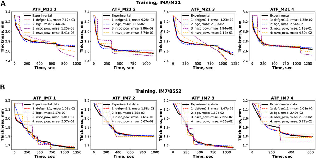
FIGURE 10. Training results. RMSE—root mean square error; (A) IMA/M21, (B) IM7/8552.
The Figures illustrating step-by-step characterisation and training outcomes for IM7/8552 material can be found in the supplementary materials (Figure 11 s). The results of the models’ training for the IM7/8552 prepreg for all four tests are presented in Figure 10B (only four candidate models are shown for each test). The second-best candidate was also able to capture the material’s behaviour (especially for tests ATF_IM7 2 and ATF_IM7 3) with the error raising by 3.2% and 16.5% in comparison with the best candidate DefGen. The resulting shear models produced a visible offset from the experimental data.
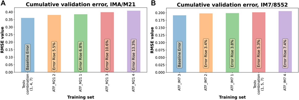
FIGURE 11. Candidate models’ ranking for different test programmes. (A) IMA/M21 material, (B) IM7/8552 material.
Since the pool of candidate models remained the same for all experiments performed within this research, it is interesting to compare the training results between IMA/M21 and IM7/8552 material systems. The training results for IM7/8552 were less accurate on average by 27%. As it can be seen from Figure 10B, the main contribution to the training error was introduced from the experiment stages with monotonic linear load increase, where top candidate models failed to fit the compaction feedback accurately. For the IMA/M21 material such phenomenon was not observed. This is an indication of the material models’ limitations to reflect the considered material’s behaviour for the specific processing conditions (monotonic load change within the chosen temperature conditions).
6 Discussion
6.1 Models’ Validation
To assess the performance of ATF, the pool of deterministic tests was separated onto training and validation tests. Training tests were used to derive material models, whereas the validation tests were deployed to compare the quality of the fit between the deterministic tests and ATF tests. Training tests were considered both in isolation and in groups. It means, that the models were trained based on all tests in the training dataset (joint fully populated set), based on only the few tests, or even single tests. The identification of data sets in diverse groups can be expected to have advantages over single tests as it increases data sets and has a richer representation of data points in load/load rate/thickness space as it was shown in (Koptelov et al., 2022). Nevertheless, having more experimental trials in the training dataset requires more time and efforts for manufacturing/experimentation/analysis. The performance of training groups was compared against all conducted single ATF tests and ranked based on validation assessment.
A maximum of three tests in the training group were considered and all possible combinations of deterministic tests were tried in the data fitting exercise. Due to the sheer number of possible training sets, the best performing combinations were picked for demonstration. The chosen training sets for IMA/M21 and IM7/852 material were (1, 4, 7) and (1, 5, 7) respectively (the number in brackets correspond to the test number shown in Figure 7). Only the results for the most populated group (consists of all three tests) are provided. For instance, the fully populated training combination (1, 5, 7) was used for comparison for the IM7/852 material, as it was better for predicting material’s response than less diverse sets (1, 5) (1, 7) (5, 7), (1), (5), (7), as it was demonstrated in (Koptelov et al., 2022).
The comparative ranking bar chart for all training tests for both IMA/M21 and IM7/852 material systems is shown in Figure 12. Each bar shows a cumulative root mean square error produced at the validation stage (the sum of fitting errors for each test at the validation stage, shown in Figure 13). The caption on top of each bar clarifies the rise of fitting error (in %) for the corresponding training set in comparison with the best performing training set (which is shown as the baseline error).
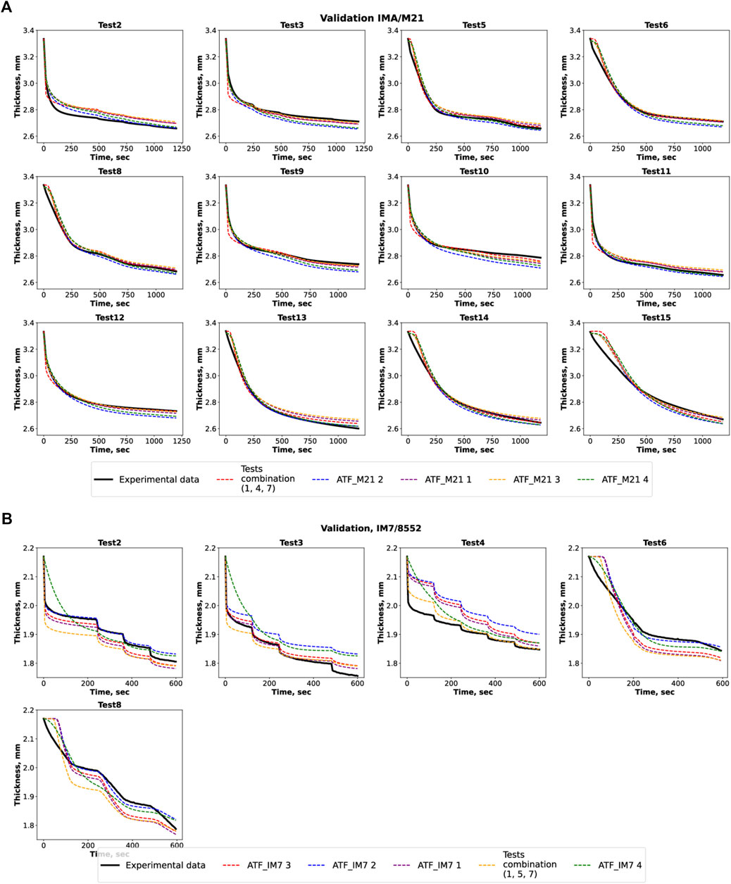
FIGURE 12. (A) IMA/M21 material testing. Candidate model’s validation; (B) IM7/8552 material testing. Candidate model’s validation.
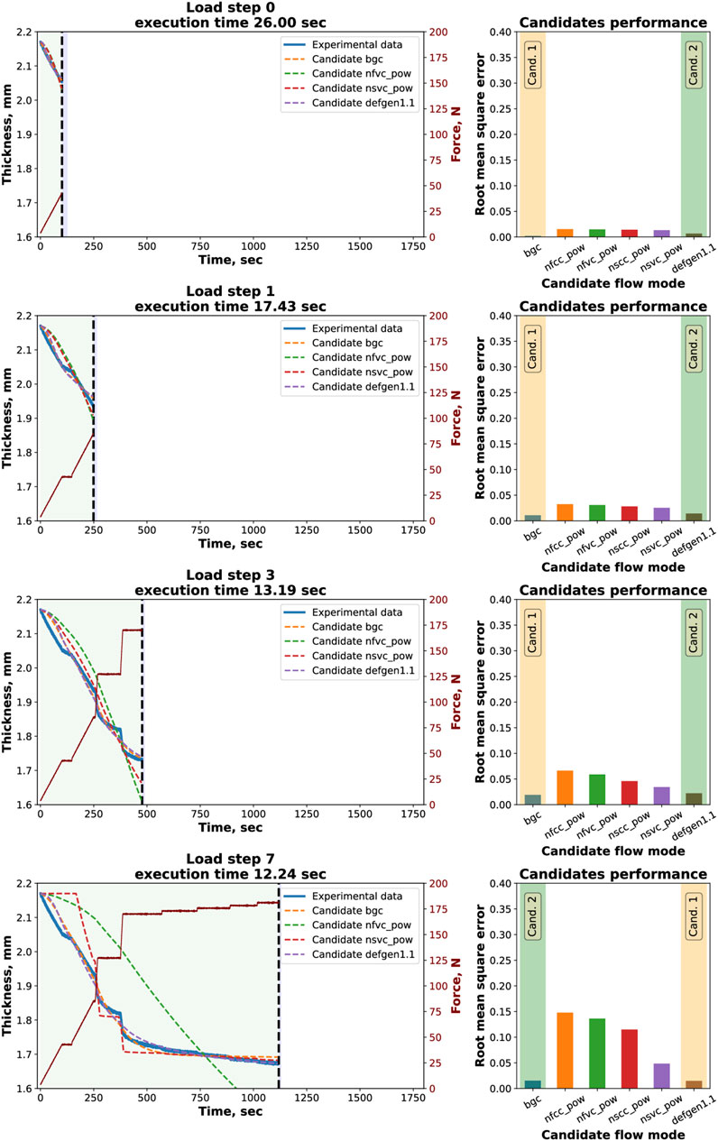
FIGURE 13. s IMA/M21 real-time experimentation step by step routine. Green region—all previously received data. Blue region (on the right from the vertical black dashed line)—required processing time.
The corresponding material parameters for the best candidate models for each characterisation test are presented in Table 3.
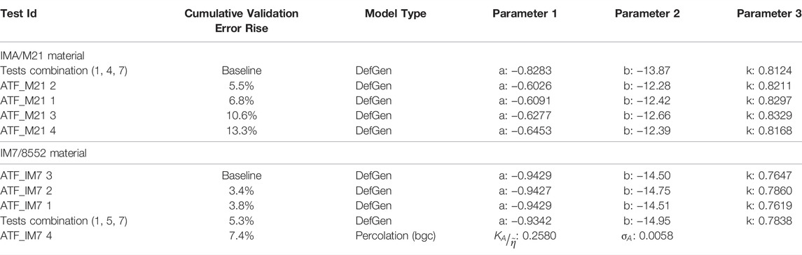
TABLE 3. Candidate models’ parameters for deterministic and real-time characterisation programmes.
From Figure 11A and Table 3 it can be seen that for the IMA/M21 material the model based on training combination of three tests (1, 4, 7) performs better on the validation data set than models obtained within the ATF approach. None of the single deterministic tests (1), (4), (7), nor several double tests (1, 4) (4, 7), outperform any of the ATF tests though. The second- and the third-best real-time tests (ATF_M21 2 and ATF_M21 1) demonstrated better data fit than less diverse two-test (1, 4) (4, 7) deterministic training combinations (the performance for two- and one-test deterministic training sets is not reflected in the comparative bar chart in Figure 11A; the comparative bar chart for these training sets can be found in Figure 14 s). As shown in Figure 14 s, the maximum error rise for double-test combinations (1, 4) (1, 7) (4, 7) was 8.6% which is higher than 5.5% and 6.5% for tests ATF_M21 2 and ATF_M21 1 respectively. The worst result for deterministic tests ((4) training combination as per Figure 14 s) was 27.3% error rise which is more than double the least effective result for the real-time test ATF_M21 4 (error rise 13.3%). It is possible to conclude, that within the conducted experimentation for IMA/M21 material the real-time tests were more effective than the majority of double- and single-test deterministic alternatives. Nevertheless, the fully populated dataset (1, 4, 7) still yielded a better result than the rest of the tests.
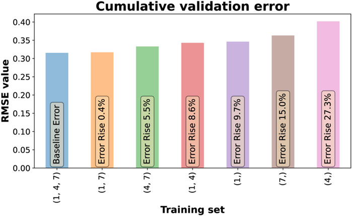
FIGURE 14. s Comparative bar chart for all possible deterministic training set combinations (1, 4, 7) for IMA/M21 material.
The resulting thickness predictions for all derived models within the validation set are shown in Figure 13A. It can be seen on the graphs that for certain validation tests the ATF models were less effective in producing a realistic prediction (tests 3, 6, 9, 10, 12) and produced an offset from the experimental data. The validation for these tests made the most contribution to the cumulative error of the real-time models reflected in the bar chart above. For the validation tests 5, 8, 11, 14, 15 the prediction capability of the real-time models was on the same level as for the fully populated deterministic model (1, 4, 7)—the compaction curves overlapped with the experimental data. For the tests 2, 11, 13 the prediction of the real-time models was more accurate and showed no deviations from the material’s response in comparison with the deterministic model.
For IMA/M21 material the framework consistently identified the DefGen model as the most relevant model to represent the material behaviour for all testing programmes. The material parameters’ values for the real-time candidate models were consistent with a maximum deviation of 6.6%, 1.1%, and 2.0%, for the parameters a, b, and k respectively (as shown in Table 3). On the other hand, the maximum difference between real-time and deterministic models’ parameters was 34.7%, 12.2%, and 2.4% (for a, b, and k). The largest discrepancy in parameters was registered for the material parameter a.
As shown in Figure 11B and Table 3, for IM7/8552 the expanded deterministic dataset was ranked fourth with an error increase of 5.3% in comparison with the highest-ranked real-time test ATF_IM7 3. Tests ATF_IM7 2 and ATF_IM7 1 showcased a similar performance with an error rise of 3.4% and 3.8% respectively. The increase in cumulative error for the last-ranked characterisation programme ATF_IM7 4 was 7.4%. Therefore, three out of four real-time programmes outperformed the deterministic three-test training set. This is an important conclusion, as it means that less experimental efforts (sample preparation, testing time, complexity of processing) were required for the successful material characterisation.
The models’ thickness predictions for IM7/8552 experimentation within each test in the validation set are presented in Figure 13B. As it was concluded before (at the stage of model training), the defined models for IM7/8552 material demonstrated a higher value of fitting error in comparison with the IMA/M21 and produced a larger offset from the experimental data curve. The same trend can be observed at the validation stage as well. All models struggled to fit the stages of linear load increase (Test 6, Test 8) of compaction. The highest level of the prediction offset was registered for the validation Test 4. However, the maximum deviation in the value of the final thickness within all validation tests did not exceed 4.4%.
The deviation in the values of material parameters a, b, and k was registered at the level 1.0%, 3.1%, 3.2% respectively as shown in Table 3. It should be noted, that for the ATF_IM7 4 test the percolation model was defined as the most accurate during the validation (lower value of the cumulative error). In comparison with other characterisation programmes, ATF_IM7 4 test was ranked fifth during the validation stage (as shown in Figure 12B).
Overall, the ATF demonstrated the ability to develop testing programmes without human intervention. For both prepregs, the resulting material models were developed with fewer conducted tests in comparison with the deterministic approach. This results in less manufacturing and material consumption required for the successful characterisation of composite precursors.
Besides the material models, the ATF can provide interesting information on the evolution of the flow process. For instance, the analysis of the step-by-step characterisation routine of the IM7/8552 material (Figure 11 s) shows, that at the initial stages of the test the percolation model was ranked first. For IMA/M21 shear models were more favourable than the DefGen in the beginning of a test (Figure 9). It may be the indication of the change of a flow pattern as the compaction goes on. Currently, the framework does not aim at detecting flow transition. In its current form, the ATF analyses the entire test: each model is applied to describe to the whole thickness-pressure history, and not just isolated periods with different dominant flow modes. However, there is a clear direction for building that capability for the ATF in future.
6.2 Conclusion
The presented adaptive testing framework was pioneered and its application to well-understood material systems examined. Integration of real-time experimentation on a universal testing machine was proven feasible. The routes for data acquisition, experimental data exchange and autonomous performance are established. The implementation of the proposed framework is achieved in conjunction with standard testing machines, the bespoke compression testing rig, the newly developed LabView state machine, the bespoke data acquisition system, and most importantly the analytical modules for the selection of load evolution.
The functionality of the proposed framework was tested within several experimental trials of two different material systems: IMA/M21 and IM7/8552 prepregs. For each material type a trend in the shape of the resulting loading programme was observed (load raise-dwell-raise, load plateau, consistent load increase etc.). Changes in the path of the loading programme during real-time testing had a direct effect on the intermediate candidate models’ ranking, which was demonstrated in the step-by-step routine. The models which performed well at the initial stages of the experiment were moved down to the second place or were even disregarded from the competition later on. Such competition between the models is the main driving mechanisms behind the performance of ATF. The biggest challenge can be observed for complex loadings, e.g. varying various strain rates and load levels with a wide range, when the ranking of models is constantly changing. Another interesting observation is that the sequential updating of candidate models at every load step allowed to correct a non-optimal set of material parameters and to provide an accurate fit of the model in the subsequent steps (IMA/M21 material, DefGen model in test ATF_M21 3).
Upon the completion of each test, the framework successfully identified the best performing material models and the corresponding set of material parameters. The obtained results for prepreg materials were trialled against a set of tests with predefined loading programmes. The validation process for IM7/8552 material confirmed, that the models trained within the adaptive experimentation showcased a superior performance in comparison with more labour-intensive deterministic training combination. The results for IMA/M21 material system indicated that the expanded set of three deterministic programmes was still preferrable, although real-time programmes were more effective than double and single-test combinations. Moreover, ATF still selected the correct material model with only a 5.5% error rise in thickness prediction in comparison with the group of three tests.
Real-time experimentation presents new challenges in regard to test reproducibility. The ATF builds its load trajectory based on the real-time feedback from a given test specimen. Material feedback may by different due to a number of factors, including specimen variability, machine’s control etc. Different specimens may flow differently under the same processing conditions. In such case ATF may output a different load trajectory. That aspect was one of the reasons for the real-time experimentation with different test settings, as shown in Table 2. Even though the resulting test programmes were different, ATF drew the same conclusion regarding the material model for all tested material systems. Test reproducibility for the real-time experimentation introduces an interesting challenge, which could be a key for better understanding the connection between the material variability and aspects of the acting flow mechanisms.
Overall, the autonomous testing demonstrated strong potential for objective assessment of complex material systems and clear direction for further development. The main limitation of the proposed approach comes from the candidate material models in the library. “It is required that the considered models can be condensed to ODEs through a set of simplifying assumptions, as shown in Eq. 1. The system can be improved without changing its basic principles, e.g. by expanding the library of the models and including more relevant physical phenomena tailored for specific materials. Moreover, the computational resources must be sufficient to output the ATF response without delays during real-time experimentation.
The obtained results allow to rethink the conventional approach to characterisation of complex material systems. The use of the proposed ATF can reduce the required amount of manufacturing and experimental trials.
Data Availability Statement
The raw data supporting the conclusion of this article will be made available by the authors, without undue reservation.
Author Contributions
AK, JP-HB, and DI contributed to conception and design of the study. AK and DI contributed to the methodology of the experimentation. JP-HB, IG, SH, and DI performed supervision and review. AK performed experiments, data analysis and wrote the first draft of the manuscript. All authors contributed to manuscript revision, read, and approved the submitted version.
Funding
This work was supported by the Engineering and Physical Sciences Research Council (EPSRC) through the Centre for Doctoral Training in Advanced Composites Collaboration for Innovation and Science (grant number EP/L016028/1) and SIMulation of new manufacturing PROcesses for Composite Structures (SIMPROCS) (grant number EP/P027350/1).
Conflict of Interest
The authors declare that the research was conducted in the absence of any commercial or financial relationships that could be construed as a potential conflict of interest.
Publisher’s Note
All claims expressed in this article are solely those of the authors and do not necessarily represent those of their affiliated organizations, or those of the publisher, the editors and the reviewers. Any product that may be evaluated in this article, or claim that may be made by its manufacturer, is not guaranteed or endorsed by the publisher.
Supplementary Material
The Supplementary Material for this article can be found online at: https://www.frontiersin.org/articles/10.3389/fmats.2022.864584/full#supplementary-material The datasets for this study can be found in the “Adaptive real-time characterisation of composite precursors in manufacturing“ repository (doi: 10.5523/bris.1omtin2rdtf3620zbjrcowa4km).
References
Almeida, J. H., Ornaghi, H. L., Lorandi, N., Marinucci, G., and Amico, S. (2018). On Creep, Recovery, and Stress Relaxation of Carbon Fiber-Reinforced Epoxy Filament Wound Composites. Polym. Eng. Sci. 58 (10), 1837–1842. doi:10.1002/pen.24790
Belnoue, J. P.-H., MesogitisNixon-Pearson, T., Nixon-Pearson, O. J., Kratz, J., Ivanov, D. S., Partridge, I. K., et al. (2017). Understanding and Predicting Defect Formation in Automated Fibre Placement Pre-preg Laminates. Composites A: Appl. Sci. Manufacturing 102 (November), 196–206. doi:10.1016/j.compositesa.2017.08.008
Belnoue, J. P.-H., Nixon-Pearson, O. J., Ivanov, D., and Hallett, S. R. (2016). A Novel Hyper-Viscoelastic Model for Consolidation of Toughened Prepregs under Processing Conditions. Mech. Mater. 97 (June), 118–134. doi:10.1016/j.mechmat.2016.02.019
Belnoue, J. P.-H., Nixon-Pearson, O. J., Thompson, A. J., Ivanov, D. S., Potter, K. D., and Hallett, S. R. (2018). Consolidation-Driven Defect Generation in Thick Composite Parts. J. Manufacturing Sci. Eng. Trans. ASME 140 (7). doi:10.1115/1.4039555
Belnoue, J. P.-H., Valverde, M. A., Onoufriou, M., Sun, X., IvanovIvanov, D. S., and Hallett, S. R. (2021). On the Physical Relevance of Power Law-Based Equations to Describe the Compaction Behaviour of Resin Infused Fibrous Materials. Int. J. Mech. Sci. 199, 106425. doi:10.1016/j.ijmecsci.2021.106425
Bréard, J., Henzel, Y., Trochu, F., and Gauvin, R. (2003). Analysis of Dynamic Flows through Porous Media. Part II: Deformation of a Double-Scale Fibrous Reinforcement. Polym. Compos. 24 (3), 409–421. doi:10.1002/pc.10039
Castellanos, D., Martin, P. J., Butterfield, J., McCourt, M., Kearns, M., and Cassidy, P. (2020). Sintering and Densification of Fibre Reinforcement in Polymers during Rotational Moulding. Proced. Manufacturing 47 (2019), 980–986. doi:10.1016/j.promfg.2020.04.301
Das, S. (2011). Life Cycle Assessment of Carbon Fiber-Reinforced Polymer Composites. Int. J. Life Cycle Assess. 16 (3), 268–282. doi:10.1007/s11367-011-0264-z
Engmann, J., Servais, C., and Burbidge, A. S. (2005). Squeeze Flow Theory and Applications to Rheometry: A Review. J. Non-Newtonian Fluid Mech. 132 (1–3), 1–27. doi:10.1016/j.jnnfm.2005.08.007
Groves, D. J. (1989). A Characterization of Shear Flow in Continuous Fibre Thermoplastic Laminates. Composites 20 (1), 28–32. doi:10.1016/0010-4361(89)90678-2
Gutowski, T. G., Cai, Z., Bauer, S., Boucher, D., Kingery, J., and Wineman, S. (1987a). Consolidation Experiments for Laminate Composites. J. Compos. Mater. 21 (7), 650–669. doi:10.1177/002199838702100705
Gutowski, T. G., and Dillon, G. (1992). The Elastic Deformation of Lubricated Carbon Fiber Bundles: Comparison of Theory and Experiments. J. Compos. Mater. 26 (16), 2330–2347. doi:10.1177/002199839202601601
Gutowski, T. G., Morigaki, T., and Zhong Cai, Cai. (1987b). The Consolidation of Laminate Composites. J. Compos. Mater. 21 (2), 172–188. doi:10.1177/002199838702100207
Haghdan, S., Tannert, T., and Smith, G. D. (2015). Effects of Reinforcement Configuration and Densification on Impact Strength of Wood Veneer/Polyester Composites. J. Compos. Mater. 49 (10), 1161–1170. doi:10.1177/0021998314531308
HEXCEL Corporation (2020). HexPly 8552 ® Epoxy Matrix (180°C/356°F Curing Matrix). Epoxy Matrix Product Datasheet. www.hexcel.com.
HEXCEL Corporation (2015). HexPly ® M21 180°C (350°F) Curing Epoxy Matrix. Epoxy Matrix Product Datasheet. www.hexcel.com.
Hubert, P., and Poursartip, A. (2001a). A Method for the Direct Measurement of the Fibre Bed Compaction Curve of Composite Prepregs. Composites Part A: Appl. Sci. Manufacturing 32 (2), 179–187. doi:10.1016/S1359-835X(00)00143-3
Hubert, P., and Poursartip, A. (2001b). Aspects of the Compaction of Composite Angle Laminates: An Experimental Investigation. J. Compos. Mater. 35 (1), 2–26. doi:10.1177/002199801772661849
Hubert, P., Vaziri, R., and Poursartip, A. (1999). A Two-Dimensional Flow Model for the Process Simulation of Complex Shape Composite Laminates. Int. J. Numer. Meth. Engng. 44 (1), 1–26. doi:10.1002/(sici)1097-0207(19990110)44:1<1::aid-nme481>3.0.co;2-k
Ivanov, Dmitry., Li, Yiqing., Ward, Carwyn., and Potter, Kevin. 2013. “Transitional Behaviour of Prepregs in Automated Fibre Deposition Processes.” in Proceedings of the 19th International Conference on Composite Materials.
Kaprielian, P. V., and O'Neill, J. M. (1989). Shearing Flow of Highly Anisotropic Laminated Composites. Composites 20 (1), 43–47. doi:10.1016/0010-4361(89)90681-2
Kelly, P. A. (2011). A Viscoelastic Model for the Compaction of Fibrous Materials. J. Textile Inst. 102 (8), 689–699. doi:10.1080/00405000.2010.515103
Koptelov, A., Belnoue, J. P.-H., Georgilas, I., Hallett, S. R., and Ivanov, D. S. (2022). Revising Testing of Composite Precursors - A New Framework for Data Capture in Complex Multi-Material Systems. Composites Part A: Appl. Sci. Manufacturing 152 (April 2021), 106697. doi:10.1016/j.compositesa.2021.106697
Lightfoot, J. S., Wisnom, M. R., and Potter, K. (2013). A New Mechanism for the Formation of Ply Wrinkles Due to Shear between Plies. Composites Part A: Appl. Sci. Manufacturing 49, 139–147. doi:10.1016/j.compositesa.2013.03.002
Matveev, M. Y., Belnoue, J. P.-H., Nixon-Pearson, O. J., Ivanov, D. S., Long, A. C., Hallett, S. R., et al. (2019). A Numerical Study of Variability in the Manufacturing Process of Thick Composite Parts. Compos. Structures 208 (January), 23–32. doi:10.1016/j.compstruct.2018.09.092
Nixon-Pearson, O., Belnoue, J.-H., Ivanov, D., Potter, K., and Hallett, S. (2017). An Experimental Investigation of the Consolidation Behaviour of Uncured Prepregs under Processing Conditions. J. Compos. Mater. 51 (13), 1911–1924. doi:10.1177/0021998316665681
Paterson, D. T., Eaves, T. S., Hewitt, D. R., Balmforth, N. J., and Martinez, D. M. (2019). Flow-Driven Compaction of a Fibrous Porous Medium. Phys. Rev. Fluids 4 (7), 1–28. doi:10.1103/PhysRevFluids.4.074306
Pipes, R. B. (1992). Anisotropic Viscosities of an Oriented Fiber Composite with a Power-Law Matrix. J. Compos. Mater. 26 (10), 1536–1552. doi:10.1177/002199839202601009
Rogers, T. G. (1989). Squeezing Flow of Fibre-Reinforced Viscous Fluids. J. Eng. Math. 23 (1), 81–89. doi:10.1007/BF00058434
Servais, Colin., Luciani, André., and Jan-AndersMånson, E. (2002). Squeeze Flow of Concentrated Long Fibre Suspensions: Experiments and Model. J. Non-Newtonian Fluid Mech. 104 (2–3), 165–184. doi:10.1016/S0377-0257(02)00018-6
Shahsavari, S., and McKinley, G. H. (2015). Mobility of Power-Law and Carreau Fluids through Fibrous Media. Phys. Rev. E 92 (6). doi:10.1103/PhysRevE.92.063012
Shuler, S. F., and Advani, S. G. (1996). Transverse Squeeze Flow of Concentrated Aligned Fibers in Viscous Fluids. J. Non-Newtonian Fluid Mech. 65 (1), 47–74. doi:10.1016/0377-0257(96)01440-1
Somashekar, A., Bickerton, S., and Bhattacharyya, D. (2007). Exploring the Non-elastic Compression Deformation of Dry Glass Fibre Reinforcements. Composites Sci. Techn. 67 (2), 183–200. doi:10.1016/j.compscitech.2006.07.032
Valverde, M. A., Belnoue, J. P.-H., Kupfer, R., Kawashita, L. F., Gude, M., and Hallett, S. R. (2021). Compaction Behaviour of Continuous Fibre-Reinforced Thermoplastic Composites under Rapid Processing Conditions. Composites Part A: Appl. Sci. Manufacturing 149, 106549. doi:10.1016/j.compositesa.2021.106549
Keywords: resin flow, consolidation, characterisation, adaptive testing, compaction
Citation: Koptelov A, Belnoue JP-H, Georgilas I, Hallett SR and Ivanov DS (2022) Adaptive Real-Time Characterisation of Composite Precursors in Manufacturing. Front. Mater. 9:864584. doi: 10.3389/fmats.2022.864584
Received: 28 January 2022; Accepted: 17 March 2022;
Published: 07 April 2022.
Edited by:
Stefano Mariani, Politecnico di Milano, ItalyReviewed by:
Hamid Akbarzadeh, McGill University, CanadaVeronique Michaud, Ecole polytechnique Fédérale de Lausanne, Switzerland
Copyright © 2022 Koptelov, Belnoue, Georgilas, Hallett and Ivanov. This is an open-access article distributed under the terms of the Creative Commons Attribution License (CC BY). The use, distribution or reproduction in other forums is permitted, provided the original author(s) and the copyright owner(s) are credited and that the original publication in this journal is cited, in accordance with accepted academic practice. No use, distribution or reproduction is permitted which does not comply with these terms.
*Correspondence: Anatoly Koptelov, YW5hdG9seS5rb3B0ZWxvdkBicmlzdG9sLmFjLnVr