 Kamalasekaran Sathasivam1,2
 Aswin kumar Anbalagan
 Chih-Hao Lee
 Tsung-Kuang Yeh
94% of researchers rate our articles as excellent or good
Learn more about the work of our research integrity team to safeguard the quality of each article we publish.
Find out more
ORIGINAL RESEARCH article
Front. Mater., 07 April 2022
Sec. Environmental Degradation of Materials
Volume 9 - 2022 | https://doi.org/10.3389/fmats.2022.863603
Austenitic stainless steels are commonly used as the base material for dry storage canisters in nuclear power plants because of their excellent corrosion resistance and mechanical properties. Dry storage canisters are often exposed to chloride-containing atmosphere near seashores that could induce localized stress corrosion cracking in these stainless steels near the welded regions. Titanium dioxide (TiO2) coatings applied on stainless steel substrates (i.e. Type 304 L stainless steels) along with ultraviolet irradiation have been proposed as a mitigation measure against corrosion in canister materials. In this study, TiO2 coatings were applied on stainless steel samples using a dip-coating method. The coated samples were then thermally treated under different annealing temperatures. Corrosion behavior and photocatalytic responses of the coated samples with and without UV illumination were evaluated by electrochemical polarization analyses and open circuit potential measurements. Surface morphologies of the samples and the crystal structures were studied by scanning electron microscopy (SEM), energy dispersive X-ray spectroscopy (EDX), and X-ray diffraction (XRD). It was found that the TiO2 coating not only showed markedly enhanced photocathodic protection on Type 304 L stainless steels during UV illumination but also maintain more active open circuit potentials for several hours after the cutoff of UV illumination. Results from electrochemical polarization analyses further supported the superior corrosion resistance of the coated samples under UV illumination conditions. In addition, the specifically processed TiO2 coatings once irradiated with UV could lead to a prolonged corrosion resistance of the samples even hours without UV illumination.
Decommissioning of nuclear reactors involves dismantling of the reactor components and the relocation of spent fuel to repository sites for final disposal. In case of the absence of a geological repository site, it is commonly accepted that dry storage inside nuclear power plants or at selected concentrated sites as an interim solution to handling spent fuel has been considered as an appropriate option (Wang et al., 2020). During the period of dry storage, metal canisters, sometimes with additional concrete or metal shields, are used to accommodate and preserve spent nuclear fuel for up to 40 years, prior to reprocessing or final disposal in a geological repository. Austenitic stainless steels are widely used as the substrate materials for dry storage canisters owing to its excellent corrosion resistance, thermal conductivity, and mechanical properties. The foregoing properties make stainless steels a desirable material for applications in various industrial plants, from food storage to solar power generation (Günen et al., 2014a). It is important to note that some of the dry storage sites, such as the nuclear power plants, may be located at areas close to seashore and the metallic materials are thus more prone to salt deposition under highly humid environments in these areas. The deposited salt could induce localized stress corrosion cracking (SCC) near the welded regions of the metallic materials and could eventually lead to structural failure of the canisters. Serious failures of the canisters accompanying with through-wall cracks could lead to the release of radionuclides toward the environment. Therefore, adequate corrosion protection measures are required for the canister materials such as stainless steels (Yeom et al., 2020). Researchers also attempted to enhance the corrosion resistance of stainless steels by surface modification techniques such as boronizing and nitriding (Günen et al., 2014b; Çetin et al., 2021). However, these techniques usually lack flexibility and require abundant efforts that make them almost impossible for large scale application.
During the past decade, cathodic protections for corrosion mitigation in stainless steels by specific metal-oxide coatings such as TiO2 (Yeh et al., 2013), ZnO2 (Techapiesancharoenkij et al., 2017), or ZrO2 (Yeh et al., 2008) irradiated with ultraviolet (UV) have drawn considerable interests. Among them, TiO2 coatings are more popular due to their inherent advantages such as superior photoelectrical properties and long-term stability in corrosive environments (Bu and Ao, 2017). Under excitation in the presence of UV illumination, TiO2 coatings can generate electron and hole pairs in the space charge layer. The generated photoelectrons are then transferred to the stainless steel surface that is exposed to a corrosive environment, making its open circuit potential more active than its original corrosion potential. The holes on the other hand would move toward the electrolyte leading to the oxidation of H2O (Yuan et al., 1994). In principle, the TiO2 coating actually acts as a non-sacrificial anode for photo-cathodic protection against corrosion in stainless steels. Efforts were devoted to the application of TiO2 coating over stainless steel substrates for corrosion mitigation, and positive results were reported (Fujisawa and Tsujikawa, 1994; Imokawa et al., 1994). However, due to the wide band gap energy of TiO2 and the recombination of electron and hole pairs in the absence of UV illumination, practical applications of TiO2 coatings have not been widely accepted (Shen et al., 2005). Other approaches have been made on metal oxides that also bear semiconductor property and have similar band gap energies compared to TiO2. Investigated examples included Fe2O3 (Liu et al., 2014), SnO2 (Subasri and Shinohara, 2003), CeO2 (Yang and Cheng (2017), and WO3 (Tatsuma et al., 2001) that all acted as photo-anodes and were separately coupled with stainless steels for corrosion mitigation. This type of photo-cathodic protection would require a relatively complicated system setup and would need to deal with the degradation of organic substances in the photo-anodic half-cell, leading to increasing production costs for large-scale industrial applications. These shortcomings may simply be overcome by the use of TiO2 coatings directly applied over stainless steels. Several techniques such as sol–gel coating, chemical vapor deposition, sputtering, spray pyrolysis, anodization, and plasma spraying for TiO2 deposition are currently available (Xu et al., 2021) (Erol et al., 2014). Among them, the sol–gel method offers many advantages in terms of coating homogeneity, well-controlled TiO2 phase structure, and good adherence over larger area. On the other hand, the factors that influence the functionality of these TiO2 coatings over stainless steels, especially low carbon Type 304 stainless steel (304LSS), have not yet been investigated in detail. For example, TiO2 coatings prepared by the sol–gel method usually require a thermal treatment at 400–500 C to achieve a desirable photocatalytic effect under UV illumination. However, such a high-temperature treatment to TiO2 coatings would also alter the microstructure of 304LSS surfaces, which could eventually lead to a poorer photocatalytic activity of these coatings (Konishi and Tsujikawa, 1997).
The undesirable outcomes of worsened catalysis in TiO2 coatings on the 304LSS substrate during high-temperature treatments have to be addressed properly before such coatings being adopted for large-scale applications. In this study, we intend not only to retain the catalytic efficiency of plain TiO2 coatings but also to prolong the cathodic protection period of the coatings even after the shutoff of UV illumination, by precisely controlling the diffusion of Fe ions from the 304LSS substrate into TiO2 coatings during annealing treatments. For a precise control over the diffusion of Fe ions, a number of parameters such as annealing temperature, annealing time, and coating thickness were considered and tested. In addition, for comparison purposes, the influences of Fe ions on the photocatalytic activity and the cathodic protection period of Fe-doped plain TiO2 coatings were investigated on indium-doped tin oxide (ITO) glass substrates. An external dopant such as ferric nitrate nanohydrate was used as a prime source of Fe in these TiO2 coatings.
Multi-layered TiO2 coatings were prepared by dipping the 304LSS substrates in TiO2-containing sol–gel solutions for a number of times, followed by appropriate annealing treatments at various temperatures for different time durations.
Electrochemical polarization analyses were conducted to evaluate the corrosion behavior of the 304LSS substrates exposed to an aqueous alkaline solution without and with the TiO2 coatings in the absence and presence of UV illumination. Surface morphologies of the substrate samples were studied by scanning electron microscopy (SEM) and energy dispersive X-ray spectroscopy (EDX). Crystalline characteristics of TiO2 coatings were evaluated by an X-ray diffraction (XRD) pattern. Depth profile analysis by secondary ion mass spectroscopy (SIMS) was conducted to quantify the amount of Fe ions having diffused into the TiO2 coatings from the substrate materials.
TiO2 coatings and coatings doped with Fe ions play important roles on both enhanced photocatalytic activity and prolonged cathodic protection for improving the corrosion resistance of coated 304LSS substrates exposed to corrosive environments. It is anticipated that this particular coating treatment could lead to a more effective reduction in the corrosion rate of the coated substrate in the presence of UV illumination and to a prolonged low corrosion rate even after the UV illumination has been switched off. During the consecutive annealing treatments for the inner anatase-type TiO2 coating and the outer amorphous TiO2 coating over the 304LSS substrate, it is expected that a considerable amount of Fe element present in the substrate would diffuse into the inner-coating layer and form Ti–O–Fe bonds, with the simultaneous formation of α-Fe2O3 and Fe3O4 in the interface between the substrate and the coating layer (Zhu et al., 2001; Yeh et al., 2013). In addition to Fe, Cr, and Ni would also diffuse into the TiO2 coating, but Fe tends to react more readily with TiO2 owing to its inherent tendency toward oxygen (Maruska and Ghosh, 1979). Furthermore, the diffusion coefficient of Fe is greater than that of Cr, which makes α-Fe2O3 and Fe3O4 to be predominant in the interfacial oxide layer. Although major ions in the interfacial oxide actually consists of both Fe2+ and Fe3+ ions, most Fe elements are present in the oxidation state of Fe3+ rather than Fe2+ since conversion from Fe2+ to Fe3+ would usually take place during planned calcination treatments (Yu et al., 2006). It is well known that Fe2O3 and TiO2 are both n-type semiconductors with two different band gap energies of 2.2 and 3.2 eV, respectively. Moreover the conduction band energy of α-Fe2O3 is lower than that of TiO2 by outer 0.38 eV. Hence, the n–n type heterojunction formed during the calcination treatment allows the photo-excited electrons to migrate easily from the outer and inner TiO2 coatings to the substrate (Huang et al., 1997).
In this study, the key to achieving a better photocatalytic activity and a prolonged cathodic protection is the preparation of multi-layered TiO2 coatings via the sol–gel-based dipping process, followed by calcination treatments at various temperatures. Suggested multi-layered TiO2 coatings depositing over the 304LSS substrate consist of two outer coatings of amorphous TiO2 and one inner anatase-type TiO2 coating underneath the amorphous coatings. It is presumed that this inner anatase-type TiO2 layer, after accommodating the Fe2+ and Fe3+ ions diffusing from the interfacial oxide during the calcination treatment, would act as a free electron donor under UV illumination. In the meantime, this specifically engineered Fe-doped layer would also become a charge storage container to trap the free electrons produced on the site and from the outer amorphous TiO2 layers, making the substrate’s electrochemical corrosion potential shifted to a more active value. The two outer amorphous TiO2 layers also serve as a barrier for preventing the stored electrons from escaping from the inner TiO2 layer once the UV illumination is switched off.
In the simultaneous presence of Fe3+ and Fe2+ ions, the Fe3+ ions would undergo a reduction reaction and become Fe2+ ions via the process of intercalated cations capturing some of the photoelectrons generated inside the TiO2 coatings during UV illumination. The remaining excess electrons would migrate through the interfacial oxide layer to the 304LSS substrate, offering photo-cathodic protection to the alloy (Huang et al., 1998). On the other hand, when the UV illumination is shutoff, Fe2+ ions tends to re-oxidize into Fe3+ ions by releasing the electrons that have been captured during UV illumination. The released electrons would continue to protect the substrate alloy from corrosion even in the absence of UV illumination. Furthermore, the two outer layers of amorphous TiO2 coatings would make it difficult for the preserved electrons to escape from coatings and react directly with the oxidizing species in corrosive environments. Eventually, the electrochemical corrosion potential of the substrate, instead of instantly moving back to the original value, would slowly rise up once the UV illumination is shutoff (Huang et al., 1998). This unique charge storage and slow release characteristics of the multi-layered TiO2 coatings, as shown in Figure 1, may help maintain the effectiveness of cathodic protection over a prolonged period of time in the absence of UV illumination. The fundamental mechanism of electron capturing and releasing is as follows (Shinohara, 2001):
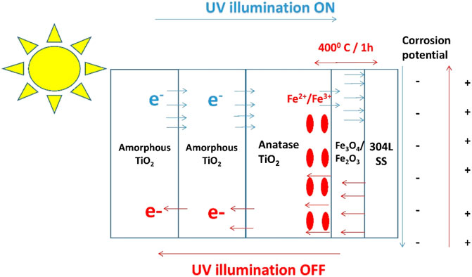
FIGURE 1. Schematic representation of amorphous TiO2/anatase-type TiO2 coatings on a 304LSS substrate and the working principle of photo-catalysis on the substrate under UV illumination.
Two different TiO2 coatings were prepared by the sol–gel calcination method using two different compositions. A Fe-doped TiO2 sol–gel solution and a plain TiO2 sol–gel one were developed separately. All the reagents were purchased from Sigma-Aldrich analytical reagent grade and used without further purification.
The Fe-doped TiO2 sol–gel solution was prepared with a designated amount of TiO2 to achieve a 10% in weight. The solution contained 2.3 g of ferric nitrate, 10.0 g of ethanol, and 29.3 g of titanium isopropoxide. The resultant brownish transparent solution was aged and used as Fe pre-doped TiO2 sol–gel for applications in the comparative study on ITO.
The plain TiO2 sol–gel solution for applications in preparing coatings on 304LSS substrates was a mixture of 29.3 g of titanium tetrapropoxide precursor, 8.0 g of anhydrous ethanol, 5 g of nitric acid, and additional 24 g of ethanol. The first two chemicals were mixed under vigorous stirring condition at 260 rpm in an ice bath for 5 min, with the solution temperature controlled at 0 C. The latter two chemicals were then added into and well-mixed with the foregoing solution to finish the sol–gel preparation. The transparent yellow sol–gel solution obtained was aged and used in constructing plain TiO2 coatings on 304LSS substrates.
Square disks made of 304LSS with a dimension of 2 cm by 2 cm by 0.5 cm were used as substrate samples. Table 1 shows the composition of the 304LSS sample analyzed by glow discharge spectroscopy (GDS). Prior to the coating process, the samples were degreased and mechanically polished with emery paper up to 600 grits and then cleansed with acetone and distilled water in an ultrasonic bath. Afterward, the samples were dipped into the plain TiO2 sol–gel solution via a commercial dip coater. In each dipping process, every sample was fully immersed in the solution for 1 min and then slowly withdrawn at a speed of 3 mm per min. The samples, coated with different layers of TiO2 and designated as 304LSS/1TO, 304LSS/2TO, and 304LSS/3TO, were subjected to annealing treatment at different temperatures of 400 and 200°C for 1 h, as listed in Table 2 with a heating ramp rate fixed at 5 C/min for all treatments. A layer of uniform, transparent, and adhesive coating was obtained over each 304LSS sample under every annealing condition. The same procedures of dip coating with various layers of plain TiO2 and Fe-doped TiO2 and thermal annealing were repeated on ITO glass substrates for pertinent comparative studies, as listed in Table 3. The annealed specimens were staged in a desiccator and then used for the photo electrochemical measurements.

TABLE 1. Chemical composition of 304LSS specimens.
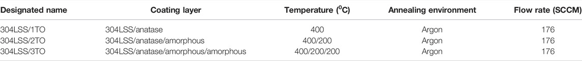
TABLE 2. Annealing treatment conditions for TiO2 over 304LSS.
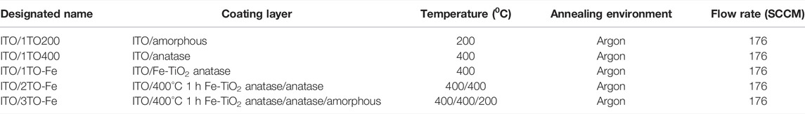
TABLE 3. Annealing treatment conditions for doped and plain TiO2 over ITO.
To determine an optimal calcination temperature for forming TiO2 coatings, thermo-gravimetric analyses (TGA) using TA instruments Q80 were adopted to analyze the thermal behavior of as prepared TiO2 sol–gel in the temperature range of 50–600 C. Optical absorption properties of the plain and Fe-doped TiO2-coated samples were measured using HP8453 (HP Germany) UV-visible spectrometer. Surface morphologies of the substrate samples were analyzed by scanning electron microscopy (SEM) by using a field emission scanning electron microscope (FE-SEM, JEOL JSM-6330F). In addition, the chemical composition of the samples was analyzed by an energy dispersion spectroscopy (EDS, Oxford INCA300, England) attached to SEM. The crystalline nature of the TiO2 coatings was evaluated by an X-ray diffraction (XRD) pattern. A depth profile analysis by secondary ion mass spectroscopy (SIMS) was conducted by using the CAMECA secondary ion mass spectrometer to quantify the amount of Fe ions having diffused into the TiO2 coatings from the substrate materials. Atomic force microscopy (AFM) was performed using the Bruker’s nanoscope to determine the coating thickness. Synchrotron X-ray diffraction (XRD) (using λ = 1.48787 Å) was performed at the end station of the TPS 09A beamline at the National Synchrotron Radiation Research Center (NSRRC), Taiwan, to study the change in the crystallinity and structure of the samples after annealing treatment at 200 and 400°C. The samples were characterized at a glancing angle of 0.5° over a two theta range of 20–35°. Sol–gel solutions were prepared using the dip coating machine sadhu design.
Potential variation monitoring and electrochemical polarization analyses were conducted with a commercial potentiostat manufactured by Corrtest Instruments to characterize the impact of UV on the open circuit potentials (OCPs) and corrosion rates of the coated 304LSS substrates. The schematic of the setup for photo-electrochemical analyses is shown in Figure 2. The analyses were conducted at room temperature in an electrolyte solution of 0.5 M of sodium bicarbonate (NaHCO3) under deaerated conditions with a pH of 8.2. The test parameters adopted in the electrochemical potentiodynamic polarization analyses were set at a potential scanning range between 100 mV lower and greater than the equilibrium potential vs. the saturated calomel electrode with a scan rate of 0.25 mV/s. Figure 2 shows the setup schematic of the three electrode electrochemical system, in which the TiO2 coated 304LSS acted as a working electrode, a saturated calomel electrode was the reference electrode, and the counter electrode was a platinum-coated titanium mesh. A 500 W Hamamatsu-made light emitter with an intensity of 4,300 mW/cm2 and a wavelength of 254 nm was used as the UV source. Prior to every measurement, all the samples were immersed in the electrolyte solution for a period of 3 h to ensure that the steady-state equilibrium was obtained.
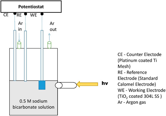
FIGURE 2. Schematic of the three-electrode electrochemical system with a potentiostat for polarization analyses. A flat transparent window was installed to provide a designated path for incident UV.
Figure 3 shows the TGA curve of TiO2 sol–gel in powder form, after being dried at 50 C for 4 h. It is clearly seen that the curve, descending from the starting temperature until it becomes flat at around 400°C, may be explained by three stages. The first stage in the temperature range of 50–120°C represents the evaporation of remaining ethanol, acid, and moisture in the powder, and around 10% weight loss was observed. Between 120 and 400°C, the declining in weight was attributed to decomposition and desorption of the organic hydroxyl compounds adsorbed on the sample, with about 9% weight loss. The amorphous TiO2 precursors was converted to anatase phase TiO2 crystals as the temperature increases from 400 to 600°C in the third stage. There was no further significant weight loss on the TGA curve after 400°C indicating that the decomposition and desorption process had completed. Accordingly, this temperature was selected as the calcination temperature for forming anatase TiO2 thin films on the substrate samples. The inferred outcome was further confirmed by XRD analyses and is discussed in the later section.
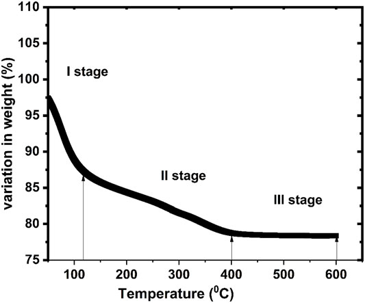
FIGURE 3. TGA curve for TiO2 sol–gel powder formed due to drying at 50 C for 4 h.
The UV–visible absorption spectra of the Fe-doped and plain TiO2 coatings applied over the ITO glass substrates were measured in the wavelength range of 300–600 nm, as shown in Figure 4. The linear extrapolation method was adopted to determine the absorption onset wavelength of the samples. The plain crystalline TiO2 coating shows an intense absorption in the UV region (around 360 nm), whereas the amorphous TiO2 coating exhibits its characteristic spectrum with an absorption onset wavelength of around 340 nm. The foregoing results indicate that both the anatase and amorphous TiO2 coatings do not have any absorption edge in the visible range. However, the absorption onset wavelength of the Fe-doped TiO2 coating is slightly shifted to about 390 nm, which lies in the visible light range and would lead to a poorer photocatalytic activity of this coating during UV illumination.
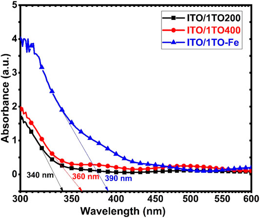
FIGURE 4. UV–visible absorption spectra for different TiO2 thin films on ITO glass.
SEM analysis was performed to determine the structural morphology of the three-layer TiO2 coating on the 304LSS substrate. The coating did not show any presence of cracks or adhesion failure after the planned annealing treatments, as shown in Figure 5. It was reported that the thermal expansion coefficient of Type 304 stainless steel is usually greater than that of a TiO2 coating, causing an interfacial stress between the substrate and the TiO2 coating (Balasubramanian et al., 2003). The TiO2 coating would thus lose its adherence on the substrate during annealing treatments if this interfacial stress is higher than the coating adherent strength. Nevertheless, no spallation or cracking was observed on the coated sample in our study. The SEM-EDS data show significant evidence of Ti and O on the sample surface, and the TiO2 coating surface was smooth without any wrinkles or non-uniform features. Furthermore, the AFM analysis results showed that the thickness of a single layer of amorphous TiO2 coating was around 105 nm whereas the thickness of the anatase TiO2 coating was too small to estimate by AFM.
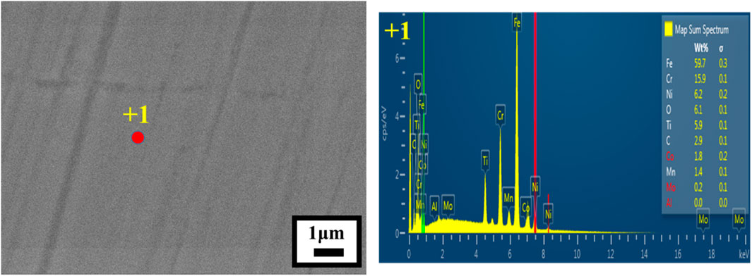
FIGURE 5. SEM image and EDX analyses results of the three-layer TiO2 coating on the 304LSS sample.
Figure 6 shows the results of depth profile analysis for the plain three-layer TiO2 coating (304LSS/3TO). It was observed that significant amounts of Fe and Cr along with Ni in a lower level are present in the coating. These foreign metal atoms diffused from the 304LSS substrate into the coating during the thermal annealing treatments (Yu et al., 2003). The amount of Fe having diffused into the TiO2 coatings is greater than those of the other two elements because the diffusion coefficient of Fe in the coating is the greatest of all (Maruska and Ghosh, 1979). It is comparatively more likely for Fe to form iron oxide at the interface between the coating and the substrate during annealing, and this would actually allow more Fe ions to diffuse into the coating. In the meantime, Ni and Cr would remain in the metallic state as they are not easily oxidized at the selected annealing temperatures. On the other hand, indications of Ti are seen in the 304LSS substrate in a very low concentration which suggests that the interdiffusion of Fe and Ti would render the TiO2 coating more adherent to the 304LSS substrate (Shang et al., 2003). Hence, the thermal annealing treatment not only helps in the crystallization of TiO2 but also makes the coating firmly reside on the substrate. As also seen in Figure 6, not the entire coating is doped with the metallic elements. A small portion near the outer surface of the coating remains uncontaminated, suggesting Fe doping might have acted as a barrier for further diffusion of the metallic elements at all thermal treatments between 400 and 200 C.
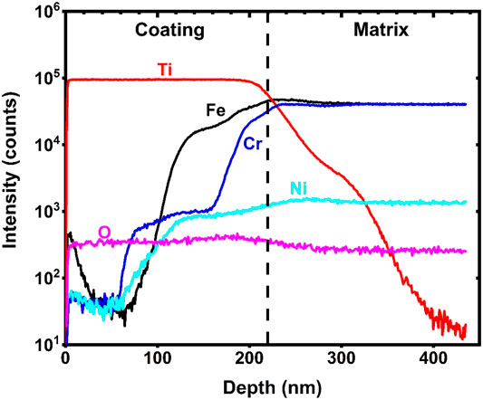
FIGURE 6. Depth profiles of Fe, Cr, and Ni in the 304LSS/3TO sample.
To characterize the structures of the TiO2 coatings under different calcination temperatures, coated ITO substrates were annealed at either 400 C or 200 C for 1 h. The technique of glancing angle XRD was adopted to analyze these samples and an uncoated ITO substrate. The results, as summarized in Figure 7, show that the crystallinity of the TiO2 coating strongly depends on annealing heat treatment temperature. The sample annealed at 200 C did not exhibit any obvious diffraction peak for TiO2 except those corresponding to the uncoated ITO substrate, indicating that this coating was amorphous in nature. On the other hand, when the annealing temperature was set at 400 C, the coating exhibited a crystalline structure. The diffraction peak at 24.5 o (101) corresponds to the tetragonal anatase phase of TiO2. The outcome is consistent with the results obtained from the TGA.
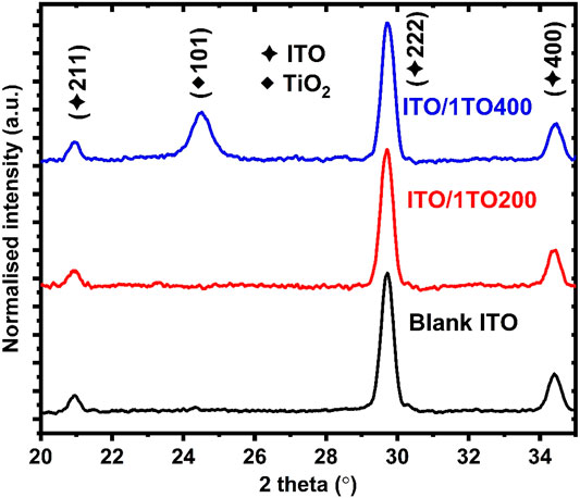
FIGURE 7. XRD analysis results of the annealed TiO2 coatings and the uncoated ITO.
The photocatalytic activities of the coatings were evaluated by OCP measurements in the designated electrolyte solution for both the ITO and 304LSS substrates.
Figure 8 shows the OCP responses of the ITO/1TO200 and ITO/1TO400 samples under dark and UV illumination conditions. Prior to UV illumination, the OCPs of the two samples were nearly the same at −0.05 VSCE. Upon the start of UV illumination, the OCPs of both samples decrease significantly to more active values, exhibiting an instantaneous photocatalytic effect. ITO/1TO400 eventually attained a stable OCP value at −0.50 VSCE. ITO/1TO200 actually reached an even more active potential of −0.62 VSCE at the beginning but slightly increased to −0.58 VSCE during the period of UV illumination. As soon as the UV was switched off, the OCP of ITO/1TO400 immediately returned to the original value because the free electrons readily recombined with the charge carriers. However, the OCP of ITO/1TO200 promptly increased to −0.15 VSCE in 30 min, about 0.1 V lower than the original value.
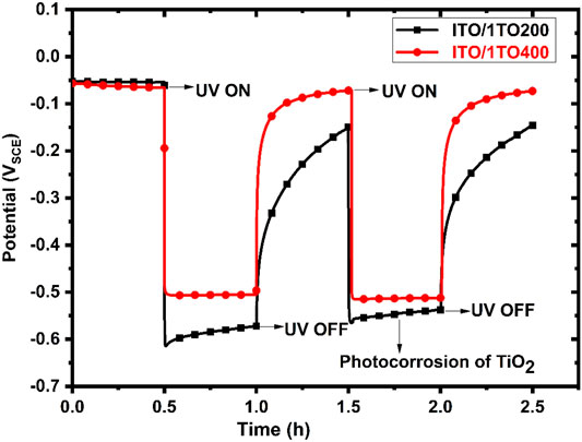
FIGURE 8. OCP responses of ITO/1TO400 and ITO/1TO200 in the designated electrolyte solution to the absence and presence of UV illumination.
When the UV was turned on for the second time, the OCP of ITO/1TOC immediately reached −0.50 VSCE again. In the meantime, the OCP of ITO/1TOM promptly decreased to −0.58 VSCE, the last recorded potential during the previous UV illumination period, which was due to the degradation of amorphous coating, also termed as photo-corrosion of TiO2 (Zhang et al., 2015). This phenomenon suggests that it would be inappropriate to use amorphous TiO2 coatings for deterring corrosion under UV illumination. The ITO/1TO400 sample, with its better crystallinity in the TiO2 coating, would allow UV-generated electrons to migrate through the space charge layer to the substrate in a relatively more stable manner. The foregoing results prove that both the crystalline and amorphous TiO2 coatings showed photocatalytic activity in generating free electrons. However, they did not bear the capability to trap electrons during UV illumination and thus could not protect the substrate materials under dark conditions.
It is anticipated that with a proper dopant such as Fe, TiO2 coating may be able to bear the charge storage property. The Fe ions as dopants in the TiO2 coating may serve to trap and store the UV-generated electrons, thus reducing their recombination with the charge carriers. The more active OCP of the coated sample during UV illumination would then return to its original value slowly once the UV is switched off, offering a prolonged protection against corrosion under dark condition. It should be also noted that even a small amount of Fe dopants incorporated within a plain TiO2 coating would drastically degrade the photocatalytic activity of the coating, leading to a much less decrease in OCP. Figure 9 shows the variations in OCP of the ITO/1TO-Fe, ITO/2TO-Fe, and ITO/3TO-Fe samples after being irradiated with UV for 1 h. It was observed that the presence of Fe ions in the TiO2 coatings led to slow increases in OCP of the three samples for more than 10 h, and one additional anatase TiO2 coating would result in a comparatively more decrease in OCP on ITO/2TO-Fe, and ITO/3TO-Fe under UV illumination. The Fe-doped TiO2 coating contained the redox couple of Fe2+/Fe3+, and Fe3+ is reduced to Fe2+ with the aid of free electrons generated under UV illumination (Huang et al., 1997). Further addition of an amorphous TiO2 coating as in ITO/3TO-Fe not only increased the photocatalytic activity but also inhibited the oxygen reduction reaction on the coating surface (Huang et al., 1998). Moreover, the amorphous coating still contained which would make the space charge layer even thicker. It would hence be more difficult for the stored electrons to escape from the Fe-doped TiO2 layer in the absence of UV illumination (Subasri and Shinohara, 2005).
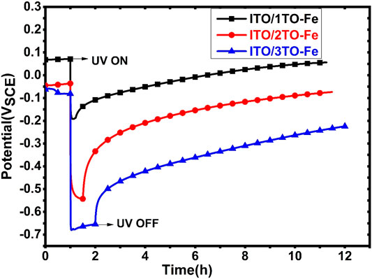
FIGURE 9. OCP responses of ITO/1TO-Fe, ITO/2TO-Fe, and ITO/3TO-Fe in the designated electrolyte solutions to the absence and presence of UV illumination.
The 304LSS/1TO, 304LSS/2TO, and 304LSS/3TO samples were separately immersed in the same electrolyte solutions for potentiodynamic polarization analyses, and the results of OCP variations of these samples in the absence and presence of UV are shown in Figure 10A Prior to the start of UV illumination, all three samples showed similar OCPs at around −0.1 VSCE, which were slightly higher than that of the uncoated 304LSS substrate (not shown in the figure). Upon the start of UV illumination, the OCPs of all samples promptly moved toward the more active (negative) direction. Among them, the OCP of 304LSS/1TO showed the least decrease of 0.1 V, and those of the other two decreased by more than 0.2 V. The same crystalline TiO2 coatings were applied to 304LSS/1TO and ITO/1TO400, but their responses of OCP to UV illumination were distinctly different. Between the off and on moments of UV, while the OCP decrease on ITO was greater than 0.4 V, and the decrease on Type 304LSS was slightly greater than 0.1 V. The less OCP decrease on 304LSS/1TO was due to the formation of an interfacial oxide layer between the substrate and the coating during the 400 C calcination treatment. At 400°C, there would be interaction between the oxide layer and the TiO2 coating, inducing the diffusion of metal ions, mainly Fe, into the TiO2 coating and degrading the photocatalytic activity (Konishi and Tsujikawa, 1997).
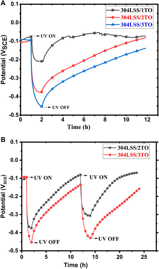
FIGURE 10. (A) OCP responses of 304LSS/1TO, 304LSS/2TO, and 304LSS/3TO in the designated electrolyte solutions to the absence and presence of UV illumination. (B) OCP responses of 304LSS/2TO and 304LSS/3TO in the designated electrolyte solutions to the absence and presence of UV illumination for two cycles.
On the other hand, all samples exhibited gradual increases in OCP when UV illumination was switched off. This slow recovery phenomenon in OCP is similar to that of the ITO/1TO-Fe sample and it took almost 2 h for the OCP to reach the original value. This again confirmed that the Fe ions having diffused into the coating played an important role in the slow increase in OCP. The Fe ions served to trap and store the UV-generated electrons, thus limiting their recombination with the charge carriers. With an additional amorphous TiO2 layer over the Fe-doped anatase layer, an improved photocatalytic effect was observed on 304LSS/2TO, and the OCP was further reduced to a more negative value to −0.38 VSCE. The addition of amorphous TiO2 also led to a slow recovery in OCP and it took nearly 8 h for the sample to return to the original OCP, due to in part the suppression of oxygen reduction reaction by this additional coating with a mechanism similar to that of the ITO/3TO-Fe sample (Huang et al., 1998). One more layer of amorphous TiO2 as in the 304LSS/3TO sample seemed even more effective in promoting photocatalytic effect and prolonging the OCP recovery time when UV was switched off. The OCP variation experiments were repeated for several cycles over the 304LSS/2TO and 304LSS/3TO specimens, and no degradation in UV-induced electrochemical characteristics of the coatings were observed as shown in Figure 10B
Potentiodynamic polarization analyses were conducted for the 304LSSS/3TO sample and the uncoated 304LSS sample exposed to a 0.5 M of sodium bicarbonate electrolyte solution in the absence of UV illumination, and the results are shown in Figure 11A Prior to each polarization analysis, the sample was immersed in the solution for a time period of 3 h to ensure that a stabilized equilibrium was reached. According to the polarization curves, the electrochemical corrosion potential ECP (−0.14 VSCE) of 304LSS/3TO is higher than that (−0.21 VSCE) of the uncoated sample by 0.07 V. The corrosion current density of the uncoated sample was 9.82 × 10⁻⁸ A/cm2. In the meantime, the 304LSS/3TO sample exhibited comparative less anodic current density of 2.07 × 10⁻⁸ A/cm2, revealing an inhibitive property of the coating and consistent with what had been observed in the literature (Zhou et al., 2009).
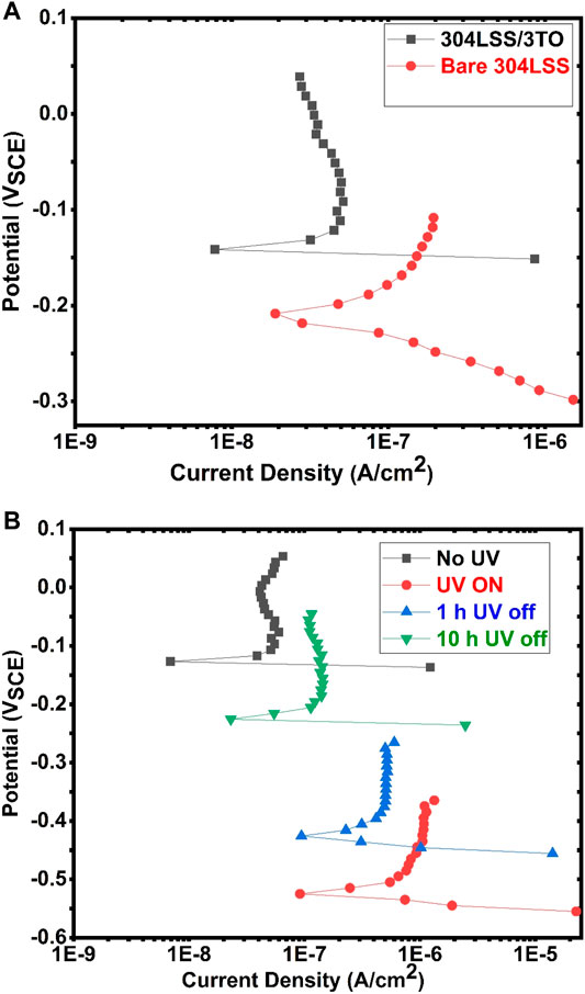
FIGURE 11. (A) Polarization curves of the uncoated 304LSS sample and the 304LSS/3TO sample. (B) Polarization curves of the uncoated 304LSS sample in the absence of UV illumination and of the 304LSS/3TO samples at different stages.
The polarization curves for the 304LSS/3TO sample under different conditions in the absence and presence of UV illumination are shown in Figure 11B, and the test conditions are summarized in Table 4. Under UV illumination, the 304LSS/3TO sample showed a markedly negative shift in corrosion potential to −0.53 VSCE, which was 0.39 V more active than that of the uncoated sample, also signifying the accumulation of UV-generated electrons. The pertinent corrosion current density was significantly lowered to 2.31 × 10⁻¹² A/cm2. On the other hand, the increase in anodic current density was attributed to the release of these electrons from the space charge layer. The change in ECP was consistent with the OCP variation in the same sample explained in the previous section. To investigate the time-dependent change in electrochemical corrosion potential and the pertinent corrosion current density of the sample, polarization analyses were further conducted at 1 h and 10 h after UV illumination was switched off. The ECP of the sample increased to −0.42 VSCE 1 h later and further increased to −0.22 VSCE 10 h later, which was in good agreement with the OCP variation of the same sample. The respective corrosion densities of the sample were determined to be 2.62 × 10⁻¹¹ A/cm2 and 3.36 × 10⁻⁹ A/cm2. It was noted that the corrosion current density of the coated sample could still remain one order of magnitude less than that of the uncoated one for 10 h in the absence of UV, indicating that the protection against corrosion in the substrate alloy was effectively prolonged with the specifically engineered TiO2 coating.
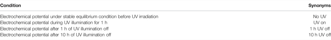
TABLE 4. Conditions set for potentiodynamic polarization analyses.
A continuous, uniform, and compact TiO2 coating was prepared on Type 304LSS substrates by the sol–gel method for prolonged corrosion mitigation. The TiO2 coating on the 304LSS/3TO sample exhibited the best photo-cathodic protection property in the corrosive environment. The 304LSS/3TO sample was cathodically protected for more than 10 h even after the cutoff of UV illumination. The corrosion current density of the 304LSS/3TO sample was still one order of magnitude less than that of the uncoated sample for 10 h without UV illumination. The novel multi-layered TiO2 coating developed in this study is able to provide an effective and prolonged photo-cathodic protection for the stainless steel substrate.
The raw data supporting the conclusions of this article will be made available by the authors, without undue reservation.
KS: investigation, formal analysis, methodology, and writing the original draft. M-YW: supervision, resources, funding acquisition, and project administration. AA: investigation and formal analysis. C-HL: supervision and resources. T-KY: supervision, conceptualization, data curation, writing—review and editing.
The authors declare that the research was conducted in the absence of any commercial or financial relationships that could be construed as a potential conflict of interest.
All claims expressed in this article are solely those of the authors and do not necessarily represent those of their affiliated organizations or those of the publisher, the editors, and the reviewers. Any product that may be evaluated in this article, or claim that may be made by its manufacturer, is not guaranteed or endorsed by the publisher.
The authors thank the Nanoscience and Technology Program, Taiwan International Graduate Program, Academia Sinica, Taiwan. The beamtime offered by NSRRC is also highly acknowledged.
Balasubramanian, G., Dionysiou, D. D., Suidan, M. T., Subramanian, V., Baudin, I., and Laîné, J.-M. (2003). Titania Powder Modified Sol-Gel Process for Photocatalytic Applications. J. Mater. Sci. 38, 823–831. doi:10.1023/a:1021869200589
Bu, Y., and Ao, J.-P. (2017). A Review on Photoelectrochemical Cathodic protection Semiconductor Thin Films for Metals. Green. Energ. Environ. 2, 331–362. doi:10.1016/j.gee.2017.02.003
Çetin, M., Günen, A., Kalkandelen, M., and Karakaş, M. S. (2021). Microstructural, Wear and Corrosion Characteristics of Boronized AISI 904L Superaustenitic Stainless Steel. Vacuum 187, 110145. doi:10.1016/j.vacuum.2021.110145
Erol, M., Dikici, T., Toparli, M., and Celik, E. (2014). The Effect of Anodization Parameters on the Formation of Nanoporous TiO2 Layers and Their Photocatalytic Activities. J. Alloys Compd. 604, 66–72. doi:10.1016/j.jallcom.2014.03.105
Fujisawa, R., and Tsujikawa, S. (1994). Cathodic Protection for Nuclear Waste Packaging under Gamma Ray Irradiation by Using TiO2 Coating Combined with Glass Scintillators. MRS Proc. 353, 735–742. doi:10.1557/proc-353-735
Günen, A., Kurt, B., Orhan, N., and Kanca, E. (2014a). The Investigation of Corrosion Behavior of Borided AISI 304 Austenitic Stainless Steel with Nanoboron Powder. Prot. Met. Phys. Chem. Surf. 50, 104–110. doi:10.1134/s2070205114010195
Günen, A., Serdar Karakaş, M., Kurt, B., and Çalık, A. (2014b). Corrosion Behavior of Borided AISI 304 Austenitic Stainless Steel. Anti-Corrosion Methods Mater. 61, 112–119. doi:10.1108/acmm-12-2012-1224
Huang, J., Konishi, T., Shinohara, T., and Tsujikawa, S. (1998). Sol-Gel Derived Ti-Fe Oxide Coating for Photoelectrochemical Cathodic Protection of Carbon Steel. Corrosion Eng. 47, 193–199. doi:10.3323/jcorr1991.47.193
Huang, J., Shinohara, T., and Tsujikawa, S. (1997). Effects of Interfacial Iron Oxides on Corrosion Protection of Carbon Steel by TiO2 Coating under Illumination. Corrosion Eng. 46, 651–661. doi:10.3323/jcorr1991.46.651
Imokawa, T., Fujisawa, R., Suda, A., and Tsujikawa, S. (1994). Protection of 304 Stainless Steel with TiO2 Coating. Corrosion Eng. 43, 482–486. doi:10.3323/jcorr1991.43.482
Konishi, T., and Tsujikawa, S. (1997). Photo-Effect of Sol-Gel Derived TiO2 Coating on Type 304 Stainless Steel. Corrosion Eng. 46, 709–716. doi:10.3323/jcorr1991.46.709
Liu, Y., Xu, C., and Feng, Z. (2014). Characteristics and Anticorrosion Performance of Fe-Doped TiO 2 Films by Liquid Phase Deposition Method. Appl. Surf. Sci. 314, 392–399. doi:10.1016/j.apsusc.2014.07.042
Maruska, H. P., and Ghosh, A. K. (1979). Transition-metal Dopants for Extending the Response of Titanate Photoelectrolysis Anodes. Solar Energ. Mater. 1, 237–247. doi:10.1016/0165-1633(79)90042-x
Shang, J., Li, W., and Zhu, Y. (2003). Structure and Photocatalytic Characteristics of TiO2 Film Photocatalyst Coated on Stainless Steel Webnet. J. Mol. Catal. A: Chem. 202, 187–195. doi:10.1016/s1381-1169(03)00200-0
Shen, G. X., Chen, Y. C., and Lin, C. J. (2005). Corrosion protection of 316 L Stainless Steel by a TiO2 Nanoparticle Coating Prepared by Sol-Gel Method. Thin Solid Films 489, 130–136. doi:10.1016/j.tsf.2005.05.016
Shinohara, T. (2001). Impedance Measurement for Slow Decline of Electrode Potential of Fe-Doped TiO2 Coating. Corrosion Eng. 50, 170–176. doi:10.3323/jcorr1991.50.170
Subasri, R., and Shinohara, T. (2003). Investigations on SnO2-TiO2 Composite Photoelectrodes for Corrosion protection. Electrochemistry Commun. 5, 897–902. doi:10.1016/j.elecom.2003.08.016
Subasri, R., and Shinohara, T. (2005). Photoelectrochemical Characterization of TiO2 Coatings Derived from Commercial Sol Solution for Cathodic protection Applications. Res. Chem. Intermed. 31, 275–283. doi:10.1163/1568567053956761
Tatsuma, T., Saitoh, S., Ohko, Y., and Fujishima, A. (2001). TiO2−WO3 Photoelectrochemical Anticorrosion System with an Energy Storage Ability. Chem. Mater. 13, 2838–2842. doi:10.1021/cm010024k
Techapiesancharoenkij, R., Sripianem, W., Tongpul, K., Peamjharean, C., Wichean, T. N., Meesak, T., et al. (2017). Investigation of the Photocathodic protection of a Transparent ZnO Coating on an AISI Type 304 Stainless Steel in a 3% NaCl Solution. Surf. Coat. Tech. 320, 97–102. doi:10.1016/j.surfcoat.2017.01.096
Wang, W.-Y., Tseng, Y.-S., and Yeh, T.-K. (2020). Evaluation of Crack Growth of Chloride-Induced Stress Corrosion Cracking in Dry Storage System under Different Environmental Conditions. Prog. Nucl. Energ. 130, 103534. doi:10.1016/j.pnucene.2020.103534
Xu, D., Liu, Y., Liu, Y., Chen, F., Zhang, C., and Liu, B. (2021). A Review on Recent Progress in the Development of Photoelectrodes for Photocathodic protection: Design, Properties, and Prospects. Mater. Des. 197, 109235. doi:10.1016/j.matdes.2020.109235
Yang, Y., and Cheng, Y. F. (2017). Bi-layered CeO2/SrTiO3 Nanocomposite Photoelectrode for Energy Storage and Photocathodic protection. Electrochimica Acta 253, 134–141. doi:10.1016/j.electacta.2017.09.044
Yeh, T.-K., Chien, Y.-C., Wang, B.-Y., and Tsai, C.-H. (2008). Electrochemical Characteristics of Zirconium Oxide Treated Type 304 Stainless Steels of Different Surface Oxide Structures in High Temperature Water. Corrosion Sci. 50, 2327–2337. doi:10.1016/j.corsci.2008.05.012
Yeh, T.-K., Huang, Y.-J., Wang, M.-Y., and Tsai, C.-H. (2013). Hydrothermal Treatments of TiO2 on Type 304 Stainless Steels for Corrosion Mitigation in High Temperature Pure Water. Nucl. Eng. Des. 254, 228–236. doi:10.1016/j.nucengdes.2012.09.012
Yeom, H., Dabney, T., Pocquette, N., Ross, K., Pfefferkorn, F. E., and Sridharan, K. (2020). Cold spray Deposition of 304L Stainless Steel to Mitigate Chloride-Induced Stress Corrosion Cracking in Canisters for Used Nuclear Fuel Storage. J. Nucl. Mater. 538, 152254. doi:10.1016/j.jnucmat.2020.152254
Yu, J. C., Ho, W., Lin, J., Yip, H., and Wong, P. K. (2003). Photocatalytic Activity, Antibacterial Effect, and Photoinduced Hydrophilicity of TiO2 Films Coated on a Stainless Steel Substrate. Environ. Sci. Technol. 37, 2296–2301. doi:10.1021/es0259483
Yu, J., Yu, H., Ao, C. H., Lee, S. C., Yu, J. C., and Ho, W. (2006). Preparation, Characterization and Photocatalytic Activity of In Situ Fe-Doped TiO2 Thin Films. Thin Solid Films 496, 273–280. doi:10.1016/j.tsf.2005.08.352
Yuan, J., Fujisawa, R., and Tsujikawa, S. (1994). Photopotentials of Copper Coated with TiO2 by Sol-Gel Method. Corrosion Eng. 43, 433–440. doi:10.3323/jcorr1991.43.433
Zhang, J., Hu, J., Zhu, Y.-F., Liu, Q., Zhang, H., Du, R.-G., et al. (2015). Fabrication of CdTe/ZnS Core/shell Quantum Dots Sensitized TiO2 Nanotube Films for Photocathodic protection of Stainless Steel. Corrosion Sci. 99, 118–124. doi:10.1016/j.corsci.2015.06.029
Zhou, M.-J., Zeng, Z.-O., and Zhong, L. (2009). Photogenerated Cathode protection Properties of Nano-Sized TiO2/WO3 Coating. Corrosion Sci. 51, 1386–1391. doi:10.1016/j.corsci.2009.03.024
Keywords: dry storage canister, 304L austenitic stainless steel, TiO2 coating, photocathodic protection, UV illumination
Citation: Sathasivam K, Wang M-Y, Anbalagan Ak, Lee C-H and Yeh T-K (2022) Prolonged and Enhanced Protection Against Corrosion Over Titanium Oxide-Coated 304L Stainless Steels Having Been Irradiated With Ultraviolet. Front. Mater. 9:863603. doi: 10.3389/fmats.2022.863603
Received: 29 January 2022; Accepted: 14 March 2022;
Published: 07 April 2022.
Edited by:
Michele Fedel, University of Trento, ItalyReviewed by:
Ali Günen, Iskenderun Technical University, TurkeyCopyright © 2022 Sathasivam, Wang, Anbalagan, Lee and Yeh. This is an open-access article distributed under the terms of the Creative Commons Attribution License (CC BY). The use, distribution or reproduction in other forums is permitted, provided the original author(s) and the copyright owner(s) are credited and that the original publication in this journal is cited, in accordance with accepted academic practice. No use, distribution or reproduction is permitted which does not comply with these terms.
*Correspondence: Tsung-Kuang Yeh, dGt5ZWhAbXgubnRodS5lZHUudHc=
Disclaimer: All claims expressed in this article are solely those of the authors and do not necessarily represent those of their affiliated organizations, or those of the publisher, the editors and the reviewers. Any product that may be evaluated in this article or claim that may be made by its manufacturer is not guaranteed or endorsed by the publisher.
Research integrity at Frontiers
Learn more about the work of our research integrity team to safeguard the quality of each article we publish.