- 1State Key Laboratory of Mountain Bridge and Tunnel Engineering, Chongqing Jiaotong University, Chongqing, China
- 2Guangxi Communications Investment Group Corporation Ltd, Nanning, China
- 3Guizhou Provincial Highway Bureau, Guizhou, China
- 4Transportation Bureau of Tian Men City, Hubei, China
The interfacial treatment between normal concrete (NC) and ultra-high–performance concrete (UHPC) is crucial to ensure bonding strength. Grooving is an effective method to treat the UHPC–NC interface, but the shear properties and failure modes at the composite interface remain under-investigated. This study focuses on the bonding performance of different groove designs (width, spacing, and angle) at the UHPC–NC interface, and push-off tests with 15 specimens were carried out to evaluate the strength and stiffness. Furthermore, a finite element model (FEM) and calculation methods were validated with the experimental study to reveal the bonding strength, and a parametric study on the groove depth was also carried out. The interface treated by grooves increases 3.32 and 2.48 times in strength and stiffness compared with specimens bonded by epoxy resin adhesive. The results also show that failing at the interface and NC matrix made up a majority of the failure modes. The shear strength of the UHPC–NC interface increased with the width and decreased with the space between the grooves. Grooves with 10 mm width, 100 mm space, 25 mm depth, and right angle were recommended. This paper will lay a foundation for the surface preparation of UHPC strengthening NC bridges.
Introduction
Ultra-high–performance concrete (UHPC) is widely defined as a cement-based material with compressive strength of no less than 150 MPa and tensile strength of no less than 8 MPa (Yoo and Banthia, 2016; Li and Deng, 2021). In addition, UHPC exhibits long-term durability due to its great impermeability (Lian et al., 2021). The potential of using the cement-based material as a repair material for strengthening normal concrete (NC) bridges is promising (Feng et al., 2020; Qin et al., 2020; Zhang et al., 2021). For the concrete bridges strengthened by UHPC, the bonding performance of the UHPC–NC interface is critical to ensure the efficiency (Murthy et al., 2018; Yang et al., 2019). The literature showed that more than 50% of structures failed due to interfacial cracking after repair or reinforcement (Li, 2004). Thus, it is essential to utilize UHPC and NC together to delay cracking at the interface (Al-Osta et al., 2017; Tong et al., 2021).
Currently, many researchers have paid attention to the interfacial behaviors of UHPC and NC. Harris et al. (2011) studied the bonding performance applying varying stress configurations and environmental conditions. The roughness of concrete substrates, bonding age, freeze–thaw cycles, and the wetting conditions of the concrete substrate were considered. The results showed that the interfacial bonding between UHPC and NC exhibited good mechanical properties as the bonding strength could be 69%–117% of the tensile strength of the NC substrate. Lee et al. (2007) evaluated the bonding durability between UHPC and NC using grooving through accelerated aging tests. Notably, the UHPC–NC interface had a relatively higher performance than the NC–NC interface during slant shear and pull-out tests. Hussein et al. (2016) and Hussein et al. (2017) researched the adhesion and friction of the UHPC–NC interface with different interfacial roughness, and the tensile strength and friction coefficient of the bonded interface were obtained. Moreover, they established a traction-separation model widely used in simulating the bond behaviors in the UHPC–NC composite structures (Zhu et al., 2020; Zhu et al., 2021). Tayeh et al. (2012) and Tayeh et al. (2013) carried out shear tests and tensile splitting tests to study the bonding ability between UHPC and NC. The test results showed that UHPC improves the microstructure of the transition zone, thus enhancing the bonding strength between the NC substrate and UHPC. To sum up, the good impermeability of the interface can significantly prolong the service life of the repaired structure. Most research focuses on the shear properties and failure modes of the UHPC–NC interfaces using different interfacial treatments.
Previous studies had shown that the shear strength increased greatly after grooved treatment. Zhang et al. (2020a) and Zhang et al. (2020b) applied 10mm and 20 mm grooves for surface treatment, and it was found that the shear strength of the NC matrix with different strengths can be improved. Besides, the specimens showed significant ductility. The bearing capacity and ductility of the grooved interface were slightly lower than those of the interface with embedded studs. Wu and Zhang (2018) researched the bonding performance between the precast ultra-high–performance concrete repair layer and existing concrete. It is recommended that grooving is an effective way, before repairing, to make the interface in the state of shearing. Jiang et al. (2020) and Jiang et al. (2021) compared the vertical groove, groove formed by high-pressure water, and different depths. It was found that the interlocking effect of aggregates produced by the groove can improve the shear strength, and 20 mm depth showed better performance compared with 10 mm and 30 mm. Ganesh and Murthy (2020) predicted the maximum failure load by the numerical method through oblique shear, splitting tensile, and four-point bending tests. The research shows that the interface with grooves presented a uniform and good mechanical performance. The interface strength can be predicted by the relationship between stress and crack width. Guan et al. (2021) evaluated the interfacial shear performance between UHPC and NC. Dimensions of the grooves and the effect of dowel rebar were considered. The UHPC–NC interface with a depth of 10 mm groove had the best mechanical performance if no dowel rebar was applied. Larger grooves had higher shear resistances due to the interlocking effect. In sum, grooving is a common treatment method for the interface connection between NC and UHPC, which can significantly improve the shear strength and slip of the interface. Its specific shapes, sizes, and spaces can still be further optimized. However, failure mechanisms, numerical simulation, and calculation methods need to be further explored.
In view of the limited research on the mechanisms and shapes of grooves between UHPC and NC, this paper carried out the push-off experiment (EXP). Different widths (10 mm, 20 mm, and 30 mm), spaces (50 mm, 75 mm, and 100 mm), and angles (-11°, 0°, and 11°) were considered. By comparing UHPC–NC bonded by epoxy resin adhesive, the influence on interface strength and stiffness with various shapes was discussed, and a recommended groove size was obtained. In addition, the finite element model (FEM) was established using the concrete damaged plasticity (CDP) model and then validated with the strength–slip curves obtained from the EXP. Calculation methods to obtain the strength of interface were provided. After that, a parametric analysis for different depths was conducted. The results can support the interface treatment of NC structures before repairing with UHPC.
Experimental Program
Description of Specimens
In order to explore the bonding performance of the UHPC–NC interface with grooves, Z-shaped specimens were selected for the push-off experiment. The design of specimens refers to the study by Wu and Zhang (2018). The pressure area is
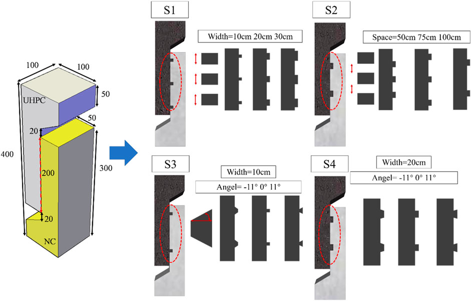
In this experiment, five groups of three specimens were designed, as shown in Figure 1. The depth of the groove is 10mm, and the main parameters are shown in Table 1. The interfaces of the S5 group are bonded with epoxy resin adhesive, and the interfaces of the other four groups are treated with grooving. The groove width of the S1 group includes 10mm, 20mm, and 30mm; the groove space of the S2 group includes 50mm, 75mm, and 100 mm. Different groove angles are considered in S3 and S4 groups. In addition, the width of the S3 group is 10mm, and the width of the S4 group is 20 mm. After calculation, when the angle between the inclined edge of the trapezoidal groove and the normal direction of the bonding surface is less than 22°, the interfacial friction is greater than the tangential force along the inclined surface, which will prevent the interfacial slip in order to facilitate the fabrication of the specimens, and different angles including 11°, 0°, and -11° are chosen.
Epoxy resin adhesive is used for the S5 group as the bonding material. Its applicable temperature is -60 °C to -120 °C. The initial curing time is 2 h, and it gets completely cured after 24 h with shear strength
Materials
The mix proportions of NC and UHPC are given in Supplementary Table 1. UHPC, which was mixed with flat steel fibers of 2% volume ratio, 8 mm length, and 0.12 mm diameter, was produced by Hunan Gu Li Engineering New Material Company, and the nominal tensile strength of the fiber was 2,700 MPa.
According to the relevant codes for concrete mechanical properties (GB/T 50081-2002 (2002) (Standard for Test Method of Mechanical Properties on Ordinary Concrete, 2002) for NC and GB/T 31387-2015 (2015) for UHPC, respectively) (Reactive Powder Concrete, 2015), the compressive strength of concrete was obtained by cubic specimens with dimensions of
Mechanical Properties of NC and UHPC
Manufacturing of the Specimens
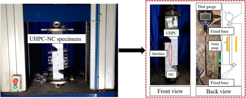
The fabrication process of the specimens is shown in Supplementary Figure 2. The formwork was made according to the design size (Figure 2A). After that, NC was poured into the formwork (Figure 2B). Twenty-eight days after the NC side was formed, the specimens were grooved with water cutting (Figure 2C). Then, the other side of the UHPC formwork was nailed to NC after cutting, and then the UHPC part was poured into it to finish the fabrication process (Figure 2D). In order to ensure the formwork can be fully and evenly filled with UHPC and enhance the bonding performance, the interface is kept wet during pouring UHPC. The formworks were removed after 24 h for normal temperature curing and steam-cured at 90°C for 48 h. After that, the specimens were allowed to cure for 7 days at normal temperature.
Loading Arrangement
The bond strength was measured using the single-side shear test method, as shown in Figure 2. All specimens were tested using the 200 kN MTS testing machine and preloaded with 5kN as the control load before formal loading. The loading was conducted at a rate of 6kN/min. When the crack or interface slip appeared, the loading transformed to control by displacement at 0.05 mm/min rate. The interfacial bonding strength was obtained by the MTS testing machine. A dial gauge was arranged at the back of the specimens to assist in measuring the bonding slip of the interface. This loading and test arrangement has been used by other researchers (Wu and Zhang, 2018).
Finite Element Models
Commercial software ABAQUS was chosen to simulate the experiment. Considering that the loading rate of the experiment is slow, the standard (static general) solver is applied in ABAQUS. Detailed information on material properties, meshing, boundary conditions, and interactions is described in the following sections.
Constitutive Model of Materials
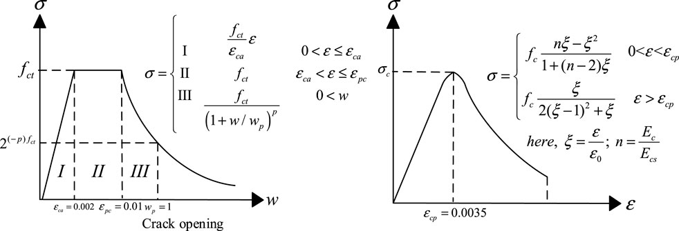
The concrete damaged plasticity (CDP) model in ABAQUS is based on the relations between stress and strain of concrete materials under tension and compression. It characterizes the inelastic behavior of concrete through tension and compression damage theories, which shows different yield strengths in compression and tension (Shafieifar et al., 2017).
NC
The constitutive law of NC is obtained through the calculation equation defined in GB50010-2010 (Code for Design of Concrete Structures, 2011), and the concrete damaged plasticity model is used, as shown in Supplementary Figure 3.
For NC under compression, the stress–strain curves can be calculated through the following equations:
where
The stress–strain curve can be calculated for NC under tension as
where
UHPC
The concrete damaged plasticity model in ABAQUS is used to represent the constitutive law of UHPC. The stress–strain relationship under tension and compression is based on the CDP model (Wang et al., 2019), as shown in Figure 3. In this relationship,
FE Meshing
Three-dimensional eight-node (C3D8R) elements were used to simulate UHPC and NC with reduced integration to avoid the locking phenomenon. These elements have three translational degrees of freedom in each node with linear interpolation for the displacement. Moreover, a general size mesh is applied for the models, and the scale is 5 mm to obtain independent results from the mesh. Details of FE meshing for models of push-off tests are depicted in Supplementary Figure 4.
Boundary Conditions and Interactions
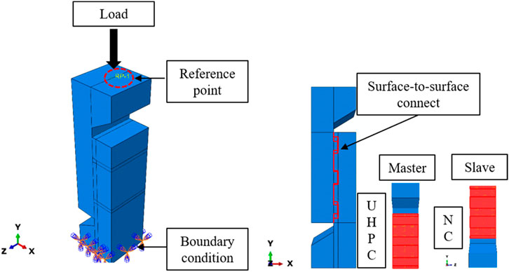
According to the experimental scheme, rotations and displacements of the bottom of the push-off specimens were restrained in X-, Y-, and Z-directions. A reference point was coupled with the loading surface, as shown in Figure 4. The displacement-controlled loading is used in the finite element analysis to obtain the strength–slip curves. Besides, geometric non-linearity is considered.
Assuming that grooves fully connect the UHPC–NC interface, therefore, surface-to-surface contact can be applied for interaction. Finite sliding and no adjustment are chosen. The contact is characterized by tangential behavior and normal behavior. In ABAQUS, the penalty function is used to describe the relationship between the tangential friction and the relative slip of the interface. When the slip reaches the limit value of 1, the friction will remain constant. A friction coefficient was implemented in which finite slip was allowed between the contact surface of UHPC and NC. The value of friction coefficient was recommended by AASHTO, which is 0.6 for the NC surface without any roughness treatment (AASHTO, 2016). Normal behavior is mainly represented by the relationship between normal stress and opening. Hard contact was applied to depict the behavior of normal bonding. Separation is allowed after contact. That is to say, no penetration is allowed at each constraint location, and the surfaces transmit no contact pressure unless the nodes of the slave surface contact the master surface. Moreover, there is no limit to the magnitude of contact pressure transmitted when the surfaces are in contact. Finite sliding was set in normal behavior in ABAQUS (Chen and Graybeal, 2012; Nasrin and Ibrahim, 2018).
Discussion of the Results
Failure Modes
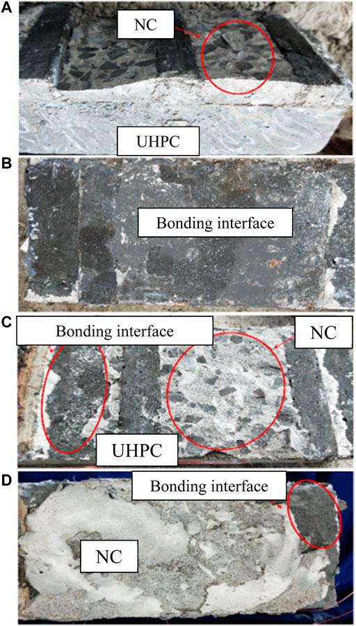
During the push-off tests, cracks appeared near the UHPC–NC interface and intersected or paralleled it. Most specimens did not fail due to eccentric compression. The failure modes of UHPC–NC specimens connected with grooves are shown in Figure 5. It can be seen that the NC matrix failed significantly in group S1, and the other groups mostly failed at the interface between UHPC and NC. Four types can be divided according to the failure modes.
The failure occurred at the NC matrix only (Figure 5A): the shear strength at the initial loading stage was mainly provided by the cohesion between UHPC and NC. Firstly, tiny shear cracks were observed on the NC matrix near the bonding surface, and then the shear bearing capacity was mainly provided by the NC matrix. With the loading process, the shear crack penetrated through the NC matrix. Then, the NC matrix was shear failed, and the failure surface was mainly on the NC matrix near the bonding area. Besides, the bonding interface of UHPC–NC remained intact, the aggregate of NC at the failure surface partly broke, and the exfoliated NC was still bonded to the UHPC.
The failure occurred at the bonding interface only (Figure 5B): the shear strength at the initial stage of loading was mainly provided by the cohesion between UHPC and NC. Firstly, tiny shear cracks were observed on the bonding surface, and the shear resistance was mainly provided by UHPC grooves which inhibit the propagation of cracks. However, with the loading process, the crack propagated vertically along the interface. Finally, the shear crack penetrated the interface, and the shear failure occurred at the bonding surface. The interface of the specimens was split into two parts, and there appeared no crack on the NC matrix and UHPC.
The failure occurred at the NC matrix and interface (Figure 5C): firstly, the crack developed obliquely to the bonding surface between UHPC and NC, and UHPC grooves mainly provided the shear strength. As the loading continued, when the load increased to 90% of the ultimate load, the bridging effect of steel fibers can be observed. Finally, the crack propagated obliquely through the NC matrix’s bonding surface. Meanwhile, the bonding interface and the NC matrix failed nearly simultaneously. The failure surface was partly on the bonding interface and the NC matrix. The bonding interface of UHPC–NC was partially cracked, while the NC matrix was damaged near the interface, and the exfoliated coarse aggregate was still bonded to UHPC.
The failure occurred at the NC matrix and interface (Figure 5D): it is similar to the failure mode of type C, but less UHPC is attached to the failure surface. The cohesion between UHPC and NC mainly provided the shear resistance at the initial loading stage. Firstly, a tiny shear crack appeared on the epoxy resin adhesive layer. The shear crack developed obliquely to the NC matrix with the loading process and finally penetrated. The shear failure occurred between the bonding interface and the NC matrix and was partly observed on the epoxy resin adhesive layer and the NC matrix. Most of the exfoliated NC was still bonded to the UHPC matrix.
The failure mode of S1-1 was A (Figure 6A), the bonding interface remained intact, and cracks only appeared at the side of the NC matrix. The failure modes of S1-2 and S1-3 specimens were type C. The failure surface was consistent with the interface. Cracks only occurred at the side of the NC matrix.
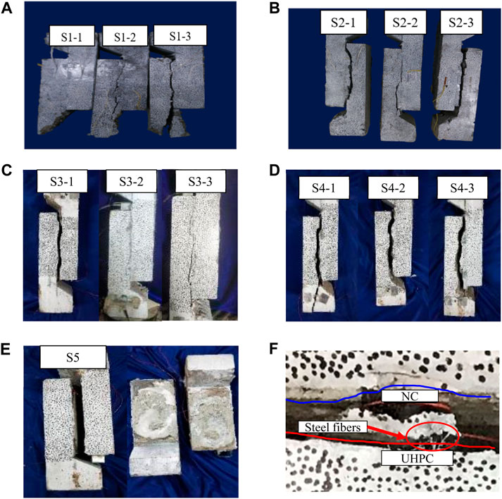
FIGURE 6. Failure modes of interface. (A) S1. (B) S2. (C) S3. (D) S4. (E) S5. (F) Steel fibers and cracks at the interface.
The failure modes of the S2-3 specimen were B (Figure 6B), the bonding surface was damaged, and there were no cracks in the matrix on both sides. The failure mode of S2-2 was C, the failure surface was consistent with the bonding surface, and cracks occurred on the side of the NC matrix. Transverse cracks developed in the middle of the NC matrix.
The failure mode of the S3-1 specimen was type B (Figure 6C), the failure surface was the bonding interface, and there appeared no cracks in the matrix on both sides. The failure mode of the S3-2 specimen was type C, part of the failure surface was consistent with the bonding interface, and the other cracked at the side of the NC matrix. The failure mode of the S3-3 specimen was B.
As for S4 and S5 groups, the failure mode of the S4 group was class C (Figure 6D, Figure 6E). The failure surface is within 10–20 mm from the edge of the bonding interface. Besides, there were no cracks on the UHPC side. The failure mode of group S5 was D, part of the failure surface was on the epoxy resin adhesive layer, and the other was on the NC matrix.
For specimens with small grooves, the convex UHPC was subjected to a larger load, especially when the shear surface cracked and slipped. During the process, a loud sound can be heard when the internal steel fibers were pulled out. The bridging effect of steel fibers was significant, and shear cracks appeared in both the UHPC and NC layers near the shear surface, as shown in Figure 6F. Finally, the specimens showed the failure mode of class C.
Figure 5 in the Supplementary Material shows the distribution of four failure modes, and the proportion of B (which failed at the interface only) is only 7%, indicating that the reliability of the UHPC–NC bonding interface is high. The proportion of C and D is up to 80%, indicating that the shear resistance of the UHPC–NC bonding interface with grooves is better than that of the NC matrix.
On the one hand, the water–cement ratio of UHPC is low and does not contain coarse aggregates, and the initial stress caused by temperature and shrinkage at the bonding interface is complex. When pouring UHPC, the ultra-fine silica powder in UHPC will be tightly filled on the surface of the existing concrete structure, and there will be no interlocked contact between coarse aggregates like the NC–NC interface with a dense microstructure. Due to the existence of UHPC grooves, the bonding area between UHPC and NC expands, the development of cracks is inhabited, and the ability to resist complex initial stress can be effectively improved. On the other hand, UHPC with a low water–cement ratio can reduce the porosity of the transition layer of the interface. Therefore, the bonding strength is enhanced with the increase of compactness. After the interface cracked, the specimen can still bear about 33.3% of the ultimate load and has good ductility characteristics.
Strength–Slip Curves
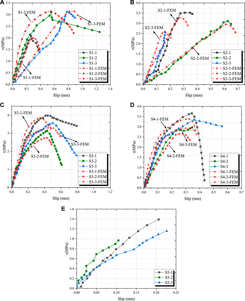
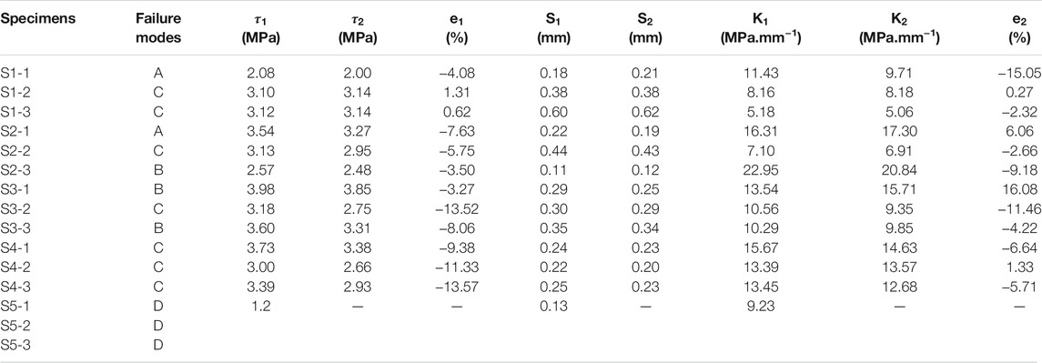
The results of the EXP and FEM are shown in Figure 7 and Table 3, where
For the S5 group, when defining the values of shear strength and stiffness in the EXP, from the perspective of safety, the maximum and minimum values of shear strength are removed, and the median value is taken as the shear strength.
It can be seen that the FEM fits well with the EXP in terms of interface strength and stiffness, and the error is within ±17%. In addition, S3-1 shows the highest shear strength of 3.98 MPa, and S2-3 shows the highest interface shear stiffness of 22.95 MPa/mm. Compared with that of the S5 group (bonded by epoxy resin adhesive), its shear strength is 1.2 MPa. The average stiffness is 9.23 MPa/mm, and the strength and stiffness are increased by 231.7% and 148.6%, respectively. The results show that grooving is very effective in improving interface performance. By comparing the failure modes, it can be found that failing at interface bonding occurs in S1-2, S1-3, and S2-2. Although the strength greatly improved compared with that of S5, their stiffness decreased. However, the stiffness of the S4 group with failure mode C increased significantly. The results show that reasonable shapes of grooves play an important role in enhancing interface performance.
Influence of the Grooves
Influence on the Bonding Strength
The change in interface strength is shown in Figure 8A. For S1, the interfacial bonding shear strength increases with the width. When the width reaches 30mm, the maximum interfacial bonding shear strength is 3.12 MPa. Due to the existence of UHPC grooves, when there appear microcracks in the bonding interface, their propagation will be restricted and the strength ductility of UHPC is better than that of NC. The greater the width of the grooves is, the greater the shear strength provided by UHPC is. Meanwhile, the grooving treatment of the bonding interface will destroy the integrity of the concrete and produce microcracks. However, the cast-in UHPC will properly fill these microcracks, and the mechanical force between the NC matrix and UHPC gets strengthened owing to the bridge effect of steel fibers. When the width of the grooves increases from 20mm to 30mm, the shear strength of the bonding interface is provided by the NC matrix, which leads to the failure of the NC matrix, i.e., failure mode C. At this time, the increase in width will not enhance the shear strength.
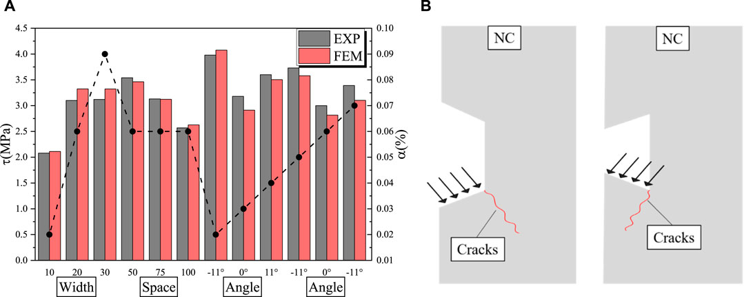
FIGURE 8. Influence of different grooves. (A) Bonding strength. (B) Crack pattern of the grooves with different angles.
For specimens of S2, the shear strength of the interface decreases with the increase of space. It is worth noting that failure modes of A occur in S2. The reason is that when the space increases, the propagation path of microcracks between grooves along the edge of the UHPC–NC interface shrinks, which will lead to interfacial failure and reduce the bonding strength.
Comparing the specimens of the S3 group and S4 group, it is found the shear strength of grooves with angle is better than that without angle. On the one hand, the interfacial bonding shear strength of -11° is about 25% higher than that of 0°; on the other hand, the interfacial bonding shear strength of 11° is about 13% higher than that of 0°.
Changing the angle can increase the strength by 1.25 times. The angle can improve the effect of interlock, so it brings higher bonding shear strength. As shown in Figure 8B, when the specimens with 11° grooves are subjected to the shear force, the shear crack will develop toward the bonding interface and aggravate the cracking of the interface. When the specimens of -11° grooves are subjected to the shear force, the shear crack will develop toward the inner part of the NC matrix, and cracking of the interface will be inhabited, therefore improving the shear resistance. In addition, the shear strength of the S3 group with 10 mm width is better than that of the S4 group with 20 mm width. It is indicated that grooves with 10 mm width perform well, and excessive width causes the failure of the NC matrix.
Influence on Bonding Stiffness
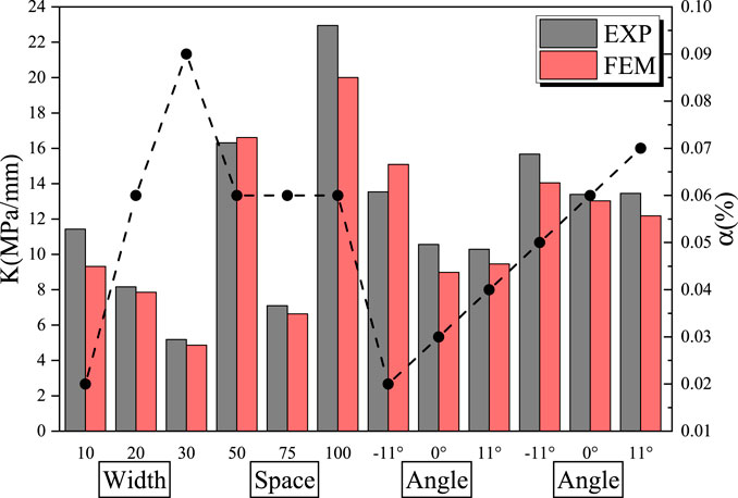
The change in interface stiffness is shown in Figure 9. For specimens of S1, the shear stiffness decreases with the increase of the width, and the shear stiffness decreases more with the volume loss rate (
For specimens of S2, S2-2 exhibits relatively low stiffness. Therefore, without considering S2-2, when the volume loss rate and width are constant, the interfacial bonding stiffness increases with space increase. The reason is that when the space of grooves increased to 100mm, the crack path from the edge of the interface decreased. Thus, the interfacial shear strength decreased. However, the propagation path of cracks between adjacent grooves extended, and the slip increased, resulting in enhancing the interfacial shear stiffness.
For specimens of S3 and S4, it can be seen that changing the angle of grooves can increase the stiffness by 1.17 times. When the angle is -11°, the interfacial shear stiffness exhibits best. It is notable that when the interface angle is 0°, the shear strength is slightly higher than that of 11°. Due to the change in the opening angle of the grooves, the interface microcracks with an angle of 11° accelerate the expansion due to the stress concentration. Besides, a relatively high volume of loss rate reduces the utilization of the shear stiffness of UHPC, therefore weakening the composite elastic modulus of the UHPC–NC interface.
Recommended Values of the Grooves
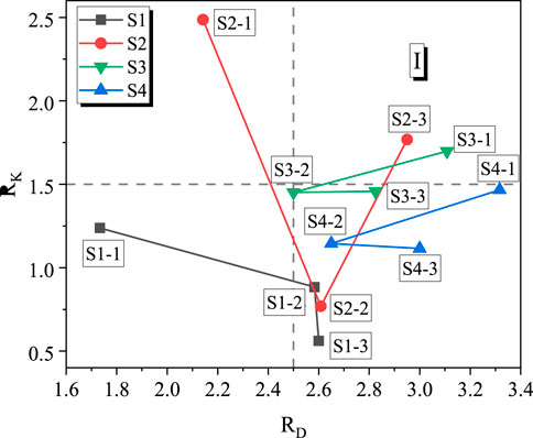
In order to compare the efficiency of different shapes of grooves at the UHPC–NC interface, the relative bonding strength
where
Calculation Methods of the Interface Shear Strength
There is currently no clear specification for calculating the shear strength of the UHPC–NC interface with grooves. ACI 318-14 (ACI Committee, 2008) provides the methods for the UHPC–NC interface strength with studs as follows (AASHTO, 2016):
where
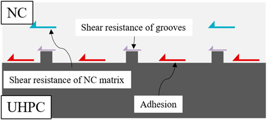
For this interface, the interface shear capacity is composed of studs’ adhesion and interfacial shear resistances. And the capacity is mainly provided by the bending of the studs that is generally referred to as dowel action, as shown in Supplementary Figure 6. However, the grooved interface is connected without studs. Considering three failure modes, the shear strength of the interface is contributed by the adhesive bonding, the NC matrix, and the shear resistance of UHPC grooves embedded in NC, as shown in Figure 11. Based on the results of the EXP, the shear strength can be calculated as follows:
where
The interface without roughness,
where
Effects of the Depth of the Grooves
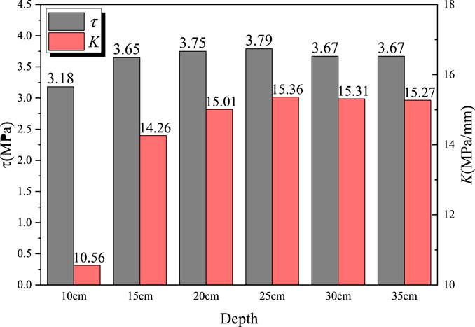
From the sections above, a more efficient UHPC–NC interface performance can be obtained with 10 mm width, 100 mm space, and right angle. Based on the FEM, which fits well with the EXP, a parametric analysis was carried out for different depths of grooves with the recommended dimensions in this paper. The interface strength and stiffness changes when the depth of grooves varies from 10mm to 35 mm were compared, as shown in Supplementary Figure 7.
The FEM results are shown in Figure 12. When the depth of grooves increased from 10mm to 15mm, the interface bonding strength and stiffness increased to 0.47MPa and 3.70 MPa/mm, respectively, the strength increased by 14.8%, and the stiffness increased by 35.0%. It is indicated that the interface bonding performance is sensitive to the depth of grooves. When the depth increased to 25mm, the interface bonding strength reached the maximum of 3.79MPa and the stiffness reached the maximum of 15.36 MPa/mm. However, when the depth increased above 25mm, the strength decreased to 3.67 MPa and remained constant with the increase of depth and the interface bonding stiffness gradually decreased to 15.27 MPa/mm. The results show that the interfacial bonding strength and stiffness increased first and then decreased with the depth increase. Grooves with 25 mm depth were recommended to improve interfacial bonding performance.
Conclusion
This paper aimed at investigating the interfacial bonding performance between UHPC and NC connected with grooves, and a push-off test with 15 UHPC–NC specimens was carried out. Conclusions can be drawn as follows:
1) Due to the grooves’ interlock effect, there is a strong mechanical performance between UHPC and NC, the development of interfacial cracks can be delayed, and the shear strength of the interface is even better than that of the NC matrix.
2) Grooves can significantly enhance the bonding performance. Besides, reasonable shapes of grooves were critical. Compared with specimens bonded by epoxy resin adhesive, the interface strength and stiffness are increased by 3.32 times and 2.48 times, respectively. Changing the angle can increase the strength by 1.25 times and the stiffness by 1.17 times. A method to calculate the bonding strength was provided.
3) The FEM was established for the push-off test. This model applied hard contact and tangential friction coefficient for the interface. From the test results, it can be found that the model can predict the shear strength and slip well, and the error was within ±17%. Based on the FEM, the parameter analysis of different depths was carried out. The interfacial bonding strength and stiffness increased first and then decreased with the depth increase. Grooves with 25 mm depth performed best.
4) Through comprehensive comparison of interfacial performance, the convenience of construction, and the volume loss rate of the matrix, grooves with 10 mm width, 100 mm space, and right angle are recommended.
Data Availability Statement
The original contributions presented in the study are included in the article/Supplementary Material, and further inquiries can be directed to the corresponding author.
Author Contributions
JY and JX wrote the manuscript. JX conceived the research idea. JW offered useful suggestions for the preparation and writing of this paper. CC collected the data. JZ and GW advised on data analysis and paper organization.
Funding
This research was performed under grants from the National Natural Science Foundation of China (U20A20314, 51908093), the Natural Science Foundation of Chongqing (cstc2020jcyj-msxmX0088), the Science Foundation of Hubei Provincial Department of Transportation (2020-186-1-6, 2020-2-1-1), and the Scientific and Technological Research Project of Chongqing Education Commission (KJQN201900733).
Conflict of Interest
The authors JY and JW were employed by Guangxi Communications Investment Group Corporation Ltd.
The remaining authors declare that the research was conducted in the absence of any commercial or financial relationships that could be construed as a potential conflict of interest.
Publisher’s Note
All claims expressed in this article are solely those of the authors and do not necessarily represent those of their affiliated organizations, or those of the publisher, the editors, and the reviewers. Any product that may be evaluated in this article, or claim that may be made by its manufacturer, is not guaranteed or endorsed by the publisher.
Supplementary Material
The Supplementary Material for this article can be found online at: https://www.frontiersin.org/articles/10.3389/fmats.2022.859717/full#supplementary-material
References
AASHTO (2016). Standard Specification for Manufacture of Precastreinforced concrete Three-Sided Structures for Culverts and Stormdrains: Astm C1504-2016. Washington DC, USA: American Association of State Highwayand Transportation Officials.
ACI Committee (2008). Building Code Requirements for Structural concrete (ACI 318-08) and Commentary. Farmington Hills, Michigan, USA: American Concrete Institute.
Al-Osta, M. A., Isa, M. N., Baluch, M. H., and Rahman, M. K. (2017). Flexural Behavior of Reinforced concrete Beams Strengthened with Ultra-high Performance Fiber Reinforced concrete. Constr. Build. Mater. 134, 279–296. doi:10.1016/j.conbuildmat.2016.12.094
Chen, L., and Graybeal, B. A. (2012). Modeling Structural Performance of Ultrahigh Performance concrete I-Girders. J. Bridge Eng. 17, 754–764. doi:10.1061/(ASCE)BE.1943-5592.0000305
Code for Design of Concrete Structures, (2011). Code for Design of concrete Structures. Gb50010-2010. Beijing, China: Ministry of Housing and Urban-Rural Development.
Feng, S., Xiao, H., and Li, H. (2020). Comparative Studies of the Effect of Ultrahigh-Performance concrete and normal concrete as Repair Materials on Interfacial Bond Properties and Microstructure. Eng. Struct. 222, 111122. doi:10.1016/j.engstruct.2020.111122
Ganesh, P., and Murthy, A. R. (2020). Simulation of Surface Preparations to Predict the Bond Behaviour between normal Strength concrete and Ultra-high Performance concrete. Constr. Build. Mater. 250, 118871. doi:10.1016/j.conbuildmat.2020.118871
Guan, D., Liu, J., Jiang, C., Chen, Z., and Guo, Z. (2021). Shear Behaviour of the Uhpc-Nsc Interface with Castellated Keys: Effects of Castellated Key Dimension and Dowel Rebar. Structures 31, 172–181. doi:10.1016/j.istruc.2021.01.088
Harris, D. K., Sarkar, J., and Ahlborn, T. M. (2011). Characterization of Interface Bond of Ultra-high-performance concrete Bridge Deck Overlays. Transport. Res. Rec. 2240, 40–49. doi:10.3141/2240-07
Hussein, H. H., Walsh, K. K., Sargand, S. M., and Steinberg, E. P. (2016). Interfacial Properties of Ultrahigh-Performance Concrete and High-Strength Concrete Bridge Connections. J. Mater. Civ. Eng. 28, 04015208. doi:10.1061/(ASCE)MT.1943-5533.0001456
Hussein, H. H., Walsh, K. K., Sargand, S. M., Al Rikabi, F. T., and Steinberg, E. P. (2017). Modeling the Shear Connection in Adjacent Box-Beam Bridges with Ultrahigh-Performance concrete Joints. I: Model Calibration and Validation. J. Bridge Eng. 22, 04017043. doi:10.1061/(ASCE)BE.1943-5592.0001070
Jiang, H., Dong, X., Fang, Z., Xiao, J., and Chen, Y. (2020). Experimental Study on Shear Behavior of a Uhpc Connection between Adjacent Precast Prestressed concrete Voided Beams. J. Bridge Eng. 25, 04020106. doi:10.1061/(ASCE)BE.1943-5592.0001644
Jiang, H., Shao, T., Fang, Z., Xiao, J., and Hu, Z. (2021). Shear-friction Behavior of Grooved Construction Joints between a Precast Uhpc Girder and a Cast-In-Place concrete Slab. Eng. Struct. 228, 111610. doi:10.1016/j.engstruct.2020.111610
Lee, M.-G., Wang, Y.-C., and Chiu, C.-T. (2007). A Preliminary Study of Reactive Powder concrete as a New Repair Material. Constr. Build. Mater. 21, 182–189. doi:10.1016/j.conbuildmat.2005.06.024
Li, J., and Deng, Z. (2021). Tensile Behavior of Hybrid Fiber-Reinforced Ultra-high-performance Concrete. Front. Mater. 8, 455. doi:10.3389/fmats.2021.769579
Li, V. C. (2004). High Performance Fiber Reinforced Cementitious Composites as Durable Material for Concrete Structure Repair/Faser verstärkte, Zement gebundene, zusammen gesetzte Hochleistungswerkstoffe für das dauerhafte Instandsetzen von Betontragwerken. Restor. Build. Monu. 10, 163–180. doi:10.1515/rbm-2004-5844
Lian, J., Hu, C., Fu, T., and Wang, Y. (2021). Review of Self-Sensing Capability of Ultra-high Performance concrete. Front. Mater. 8, 467. doi:10.3389/fmats.2021.746022
Murthy, A. R., Aravindan, M., and Ganesh, P. (2018). Prediction of Flexural Behaviour of Rc Beams Strengthened with Ultra High Performance Fiber Reinforced concrete. Struct. Eng. Mech. 65, 315–325. doi:10.12989/sem.2018.65.3.315
Nasrin, S., and Ibrahim, A. (2018). Finite-element Modeling of Uhpc Hybrid Bridge Deck Connections. Int. J. Adv. Struct. Eng. 10, 199–210. doi:10.1007/s40091-018-0192-2
Qin, F., Zhang, Z., Yin, Z., Di, J., Xu, L., and Xu, X. (2020). Use of High Strength, High Ductility Engineered Cementitious Composites (Ecc) to Enhance the Flexural Performance of Reinforced concrete Beams. J. Build. Eng. 32, 101746. doi:10.1016/j.jobe.2020.101746
Reactive Powder Concrete, (2015). Reactive Powder concrete. Gb/t 31387-2015. Beijing, China: General Administration of Quality Supervision. Inspection and quarantine.
Santos, P. M. D., and Júlio, E. N. B. S. (2012). A State-Of-The-Art Review on Shear-Friction. Eng. Structures 45, 435–448. doi:10.1016/j.engstruct.2012.06.036
Shafieifar, M., Farzad, M., and Azizinamini, A. (2017). Experimental and Numerical Study on Mechanical Properties of Ultra High Performance concrete (Uhpc). Constr. Build. Mater. 156, 402–411. doi:10.1016/j.conbuildmat.2017.08.170
Standard for Test Method of Mechanical Properties on Ordinary Concrete, (2002). Standard for Test Method of Mechanical Properties on Ordinary concrete. Gb/t50081-2002. Beijing, China: Ministry of Housing and Urban-Rural Development.
Tayeh, B. A., Abu Bakar, B. H., Megat Johari, M. A., and Voo, Y. L. (2012). Mechanical and Permeability Properties of the Interface between normal concrete Substrate and Ultra High Performance Fiber concrete Overlay. Constr. Build. Mater. 36, 538–548. doi:10.1016/j.conbuildmat.2012.06.013
Tayeh, B. A., Abu Bakar, B. H., and Megat Johari, M. A. (2013). Characterization of the Interfacial Bond between Old concrete Substrate and Ultra High Performance Fiber concrete Repair Composite. Mater. Struct. 46, 743–753. doi:10.1617/s11527-012-9931-1
Tong, T., Yuan, S., Wang, J., and Liu, Z. (2021). The Role of Bond Strength in Structural Behaviors of Uhpc-Nc Composite Beams: Experimental Investigation and Finite Element Modeling. Compos. Struct. 255, 112914. doi:10.1016/j.compstruct.2020.112914
Wang, Z., Nie, X., Fan, J.-S., Lu, X.-Y., and Ding, R. (2019). Experimental and Numerical Investigation of the Interfacial Properties of Non-steam-cured Uhpc-Steel Composite Beams. Constr. Build. Mater. 195, 323–339. doi:10.1016/j.conbuildmat.2018.11.057
Wu, X., and Zhang, X. (2018). Investigation of Short-Term Interfacial Bond Behavior between Existing concrete and Precast Ultra-high Performance concrete Layer. J. Build. Sturc. 39, 156–163. doi:10.14006/j.jzjgxb.2018.10.018
Yang, J., Zhou, J., Wang, Z., Zhou, Y., and Zhang, H. (2019). Structural Behavior of Ultrahigh-Performance Fiber-Reinforced concrete Thin-Walled Arch Subjected to Asymmetric Load. Adv. Civil Eng. 2019, 1–12. doi:10.1155/2019/9276839
Yoo, D.-Y., and Banthia, N. (2016). Mechanical Properties of Ultra-high-performance Fiber-Reinforced concrete: A Review. Cement Concrete Composites 73, 267–280. doi:10.1016/j.cemconcomp.2016.08.001
Zhang, Y., Zhu, P., Liao, Z., and Wang, L. (2020a). Interfacial Bond Properties between normal Strength concrete Substrate and Ultra-high Performance concrete as a Repair Material. Constr. Build. Mater. 235, 117431. doi:10.1016/j.conbuildmat.2019.117431
Zhang, Y., Zhu, P., Wang, X., and Wu, J. (2020b). Shear Properties of the Interface between Ultra-high Performance concrete and normal Strength concrete. Constr. Build. Mater. 248, 118455. doi:10.1016/j.conbuildmat.2020.118455
Zhang, Z., Liu, S., Yang, F., Weng, Y., and Qian, S. (2021). Sustainable High Strength, High Ductility Engineered Cementitious Composites (Ecc) with Substitution of Cement by rice Husk Ash. J. Clean. Prod. 317, 128379. doi:10.1016/j.jclepro.2021.128379
Zhu, Y., Zhang, Y., Hussein, H. H., and Chen, G. (2020). Numerical Modeling for Damaged Reinforced concrete Slab Strengthened by Ultra-high Performance concrete (Uhpc) Layer. Eng. Struct. 209, 110031. doi:10.1016/j.engstruct.2019.110031
Keywords: bridge engineering, UHPC, bonding strength, bonding stiffness, grooved interface, finite element model
Citation: Yang J, Xia J, Cheng C, Wang J, Zhang J and Wang G (2022) Research on the Bonding Performance of UHPC–NC Interfaces With Different Sizes of Grooves. Front. Mater. 9:859717. doi: 10.3389/fmats.2022.859717
Received: 21 January 2022; Accepted: 28 February 2022;
Published: 23 March 2022.
Edited by:
Xijun Shi, Texas State University, United StatesReviewed by:
Shao-Bo Kang, Chongqing University, ChinaZehra Canan Girgin, Yıldız Technical University, Turkey
Copyright © 2022 Yang, Xia, Cheng, Wang, Zhang and Wang. This is an open-access article distributed under the terms of the Creative Commons Attribution License (CC BY). The use, distribution or reproduction in other forums is permitted, provided the original author(s) and the copyright owner(s) are credited and that the original publication in this journal is cited, in accordance with accepted academic practice. No use, distribution or reproduction is permitted which does not comply with these terms.
*Correspondence: Jieyun Wang, wangjygx@126.com
 Jun Yang